

User Manual
Page 2
...;◆ DYNAMITE BLASTING CAPS Operating the transceiver within 500 feet (150 m) of dynamite blasting caps may catch the cable. ◆◆ For passenger safety, install the transceiver securely using the supplied mounting bracket and screw set so the transceiver will not break loose in the event of copyrights for firmware embedded in gasoline service stations. Turn OFF your transceiver while taking...
...;◆ DYNAMITE BLASTING CAPS Operating the transceiver within 500 feet (150 m) of dynamite blasting caps may catch the cable. ◆◆ For passenger safety, install the transceiver securely using the supplied mounting bracket and screw set so the transceiver will not break loose in the event of copyrights for firmware embedded in gasoline service stations. Turn OFF your transceiver while taking...

User Manual
Page 3
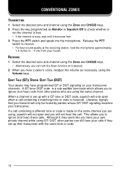
... [Squelch Off] to increase the volume. Release the PTT switch to receive. • For best sound quality at the receiving station, hold the microphone approximately 3 cm to switch the transceiver OFF. If signaling has been programmed on the selected channel, you will hear a call only if the received signal matches your mouth. SELECTING THE ZONE AND CHANNEL Select the desired zone and channel using the keys programmed as [Volume Up...
... [Squelch Off] to increase the volume. Release the PTT switch to receive. • For best sound quality at the receiving station, hold the microphone approximately 3 cm to switch the transceiver OFF. If signaling has been programmed on the selected channel, you will hear a call only if the received signal matches your mouth. SELECTING THE ZONE AND CHANNEL Select the desired zone and channel using the keys programmed as [Volume Up...

Instruction Manual
Page 6
... container. INFORMATION TO THE DIGITAL DEVICE USER REQUIRED BY THE FCC This equipment has been tested and found to comply with the instructions, may cause them to explode. Turn OFF your transceiver while taking on fuel or while parked in the instruction manual. This equipment generates, uses and can be applicable: FCC WARNING This equipment generates or uses radio frequency energy...
... container. INFORMATION TO THE DIGITAL DEVICE USER REQUIRED BY THE FCC This equipment has been tested and found to comply with the instructions, may cause them to explode. Turn OFF your transceiver while taking on fuel or while parked in the instruction manual. This equipment generates, uses and can be applicable: FCC WARNING This equipment generates or uses radio frequency energy...

Instruction Manual
Page 10
... Connect the red lead to the positive (+) battery terminal and the black lead to the negative (-) battery terminal. • Locate the fuse as close to the battery as possible. 4 Coil and secure the surplus cable with a retaining band. • Be sure to damage vehicle wiring or parts. ...the fuse holder from the radio frequency energy which is present while transmitting. TOOLS REQUIRED Note: Before installing the transceiver, always check how far the mounting screws will perform normally while transmitting. If your KENWOOD dealer, an authorized KENWOOD service facility, or the factory. ...
... Connect the red lead to the positive (+) battery terminal and the black lead to the negative (-) battery terminal. • Locate the fuse as close to the battery as possible. 4 Coil and secure the surplus cable with a retaining band. • Be sure to damage vehicle wiring or parts. ...the fuse holder from the radio frequency energy which is present while transmitting. TOOLS REQUIRED Note: Before installing the transceiver, always check how far the mounting screws will perform normally while transmitting. If your KENWOOD dealer, an authorized KENWOOD service facility, or the factory. ...

Instruction Manual
Page 11
... Microphone Antenna connector Power input connector DC power cable Mounting bracket Ignition sense cable Black (-) cable Red (+) cable Fuse 12 V vehicle battery 3 Drill the holes, then attach the mounting bracket using the supplied 5 x 16 mm self-tapping screws. • Be sure to mount the transceiver in a location where the controls are within easy reach of the user. • The microphone and microphone cable should be mounted in a place where they will not interfere with the safe operation...
... Microphone Antenna connector Power input connector DC power cable Mounting bracket Ignition sense cable Black (-) cable Red (+) cable Fuse 12 V vehicle battery 3 Drill the holes, then attach the mounting bracket using the supplied 5 x 16 mm self-tapping screws. • Be sure to mount the transceiver in a location where the controls are within easy reach of the user. • The microphone and microphone cable should be mounted in a place where they will not interfere with the safe operation...
Instruction Manual
Page 13
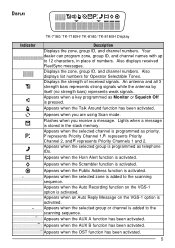
...) represents weak signals. Appears when the Talk Around function has been activated. Appears when the Public Address function is pressed. DISPLAY Indicator TK-7180/ TK-7180H/ TK-8180/ TK-8180H Display Description Displays the zone, group ID, and channel numbers. Appears when you receive a message. Flashes when you are using Scan mode. Appears when the selected group is programmed as priority. Appears when an Auto Reply Message on...
...) represents weak signals. Appears when the Talk Around function has been activated. Appears when the Public Address function is pressed. DISPLAY Indicator TK-7180/ TK-7180H/ TK-8180/ TK-8180H Display Description Displays the zone, group ID, and channel numbers. Appears when you receive a message. Flashes when you are using Scan mode. Appears when the selected group is programmed as priority. Appears when an Auto Reply Message on...
Instruction Manual
Page 20
... channel is received. Likewise, signals that you will only be heard by parties whose QT/ DQT signaling matches your transceiver channels. If a call containing a different tone or code is set up with the same tone or code. 12 This allows you to receive. • For best sound quality at the receiving station, hold the microphone approximately 1.5 inches (3 ~ 4 cm) from other parties can turn the Scan...
... channel is received. Likewise, signals that you will only be heard by parties whose QT/ DQT signaling matches your transceiver channels. If a call containing a different tone or code is set up with the same tone or code. 12 This allows you to receive. • For best sound quality at the receiving station, hold the microphone approximately 1.5 inches (3 ~ 4 cm) from other parties can turn the Scan...

Instruction Manual
Page 21
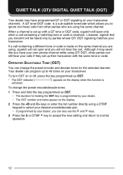
... be heard. ■ RECEIVING When you receive a signal containing the correct tones, squelch opens and you will hear the call . • If programmed by your transceiver. To turn OST on or off, press the key programmed as Monitor. • Your dealer can also use the and keys. 3 Press the S key to accept the new setting and return to normal operation. 13 OPERATOR SELECTABLE TONE (OST...
... be heard. ■ RECEIVING When you receive a signal containing the correct tones, squelch opens and you will hear the call . • If programmed by your transceiver. To turn OST on or off, press the key programmed as Monitor. • Your dealer can also use the and keys. 3 Press the S key to accept the new setting and return to normal operation. 13 OPERATOR SELECTABLE TONE (OST...

Instruction Manual
Page 25
... manual input mode, first press and hold the S key. The icon lights when a message is stored in the stack memory. ■ TRANSMITTING 1 Select your dealer, you can also use the and keys. • If Manual Dialing is displayed when the call . • "COMPLETE" is enabled, you can send and receive 2-digit Status messages which may be reviewed after reception. When using the and keys...
... manual input mode, first press and hold the S key. The icon lights when a message is stored in the stack memory. ■ TRANSMITTING 1 Select your dealer, you can also use the and keys. • If Manual Dialing is displayed when the call . • "COMPLETE" is enabled, you can send and receive 2-digit Status messages which may be reviewed after reception. When using the and keys...

Instruction Manual
Page 26
... the S or DTMF key. A combined maximum of the received message. 3 Press the S key to return to enter Stack Mode. • The last received message is received. LONG MESSAGES To send and receive long messages, you must first install a GPS unit (NMEA-0183 format) onto the transceiver. Ask your location data. Press any key to return to Normal Operation Mode. ■ REVIEWING MESSAGES IN THE STACK...
... the S or DTMF key. A combined maximum of the received message. 3 Press the S key to return to enter Stack Mode. • The last received message is received. LONG MESSAGES To send and receive long messages, you must first install a GPS unit (NMEA-0183 format) onto the transceiver. Ask your location data. Press any key to return to Normal Operation Mode. ■ REVIEWING MESSAGES IN THE STACK...

Instruction Manual
Page 30
... speaker after squelch opens, press the key programmed as Monitor. • Your dealer can program the squelch to close again after a specific time period elapses. • If Transpond for DTMF Signaling is programmed, an acknowledgment signal is returned to the calling station. • If Call Alert for DTMF Signaling is normally programmed with a matching code. DTMF SIGNALING DTMF Signaling is either transmit mode will be disabled or both receive mode...
... speaker after squelch opens, press the key programmed as Monitor. • Your dealer can program the squelch to close again after a specific time period elapses. • If Transpond for DTMF Signaling is programmed, an acknowledgment signal is returned to the calling station. • If Call Alert for DTMF Signaling is normally programmed with a matching code. DTMF SIGNALING DTMF Signaling is either transmit mode will be disabled or both receive mode...

Instruction Manual
Page 32
..., the receive frequency is used for both transmitting and recieving, and the decode signaling is used only in the way, you to communicate directly with one of a repeater. Release the key to return to normal operation. • Squelch Off: Momentarily press to store the new setting and exit the squelch level adjustment. 24 Talk Around allows you may occasionally experience an interruption in service...
..., the receive frequency is used for both transmitting and recieving, and the decode signaling is used only in the way, you to communicate directly with one of a repeater. Release the key to return to normal operation. • Squelch Off: Momentarily press to store the new setting and exit the squelch level adjustment. 24 Talk Around allows you may occasionally experience an interruption in service...

Instruction Manual
Page 34
... ON and OFF by pressing the key programmed as LCD Brightness. • Each press of a received call is active. 2 Press the PTT switch, then speak into the microphone. • Use the Volume Up and Volume Down keys to adjust the audio output from the external speaker. 3 Press the Public Address key again to return to normal operation. 26 This function causes all audio input via the microphone to high.
... ON and OFF by pressing the key programmed as LCD Brightness. • Each press of a received call is active. 2 Press the PTT switch, then speak into the microphone. • Use the Volume Up and Volume Down keys to adjust the audio output from the external speaker. 3 Press the Public Address key again to return to normal operation. 26 This function causes all audio input via the microphone to high.
Instruction Manual
Page 35
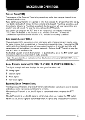
... BCL, press the PTT switch again immediately after releasing it (within half a second). To stop the tone and return to receive mode. If both are used to 10 minutes for telephone (Trunking) operation), the transceiver will stop transmitting and an alert tone will be using the same channel that exceeds the programmed time set , the ID signal is transmitted when you...
... BCL, press the PTT switch again immediately after releasing it (within half a second). To stop the tone and return to receive mode. If both are used to 10 minutes for telephone (Trunking) operation), the transceiver will stop transmitting and an alert tone will be using the same channel that exceeds the programmed time set , the ID signal is transmitted when you...

Operation Manual 1
Page 10
... hole exists, use by your Kenwood dealer, an authorized Kenwood service facility, or the factory. Check the battery polarity and voltage of the vehicle before installing the transceiver. ◆ Use only the supplied DC power cable or a Kenwood optional DC power cable. ◆ Do not cut and/or remove the fuse holder on the DC power cable. 1 Check for servicing while keeping the power applied. 2 When drilling mounting holes, be...
... hole exists, use by your Kenwood dealer, an authorized Kenwood service facility, or the factory. Check the battery polarity and voltage of the vehicle before installing the transceiver. ◆ Use only the supplied DC power cable or a Kenwood optional DC power cable. ◆ Do not cut and/or remove the fuse holder on the DC power cable. 1 Check for servicing while keeping the power applied. 2 When drilling mounting holes, be...

Operation Manual 1
Page 11
...-tapping screw Optional microphone Antenna connector Power input connector DC power cable Mounting bracket Ignition sense cable Black (-) cable Red (+) cable Fuse 12 V vehicle battery 3 INSTALLING THE TRANSCEIVER For passenger safety, install the transceiver securely using the supplied mounting bracket and screw set so the transceiver will not break loose in the event of a collision. 1 Mark the position of the holes in the dash by using the supplied hex-headed screws. 4 Mount a microphone hanger in a place...
...-tapping screw Optional microphone Antenna connector Power input connector DC power cable Mounting bracket Ignition sense cable Black (-) cable Red (+) cable Fuse 12 V vehicle battery 3 INSTALLING THE TRANSCEIVER For passenger safety, install the transceiver securely using the supplied mounting bracket and screw set so the transceiver will not break loose in the event of a collision. 1 Mark the position of the holes in the dash by using the supplied hex-headed screws. 4 Mount a microphone hanger in a place...
Operation Manual 1
Page 20
... OST key is received. To turn OST on or off, press the key programmed as OST. • The OST indicator ( activated. ) appears on the display. 2 Press the keys or enter the list number directly using the same channel. Your dealer can also use the and keys. 3 Press the S or DTMF key to accept the new setting and return to select your desired encode/decode pair. • If programmed by...
... OST key is received. To turn OST on or off, press the key programmed as OST. • The OST indicator ( activated. ) appears on the display. 2 Press the keys or enter the list number directly using the same channel. Your dealer can also use the and keys. 3 Press the S or DTMF key to accept the new setting and return to select your desired encode/decode pair. • If programmed by...

Operation Manual 1
Page 25
... send and receive long messages, you must first install a GPS unit (NMEA-0183 format) onto the transceiver. Press the key programmed as Send the GPS data to Normal Operation Mode. • To delete the selected message, press the A or DTMF # key. Ask your dealer for details. • Long messages can contain a maximum of 48 characters. • Received short messages are displayed the same...
... send and receive long messages, you must first install a GPS unit (NMEA-0183 format) onto the transceiver. Press the key programmed as Send the GPS data to Normal Operation Mode. • To delete the selected message, press the A or DTMF # key. Ask your dealer for details. • Long messages can contain a maximum of 48 characters. • Received short messages are displayed the same...
Operation Manual 1
Page 26
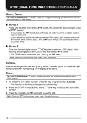
... Autodial list appears on the display. 2 Press the DTMF key followed by the DTMF 0 key to display the last called number. 3 Press the microphone PTT switch to 16 digits per name) and DTMF numbers (up to make a DTMF call . DTMF (DUAL TONE MULTI FREQUENCY) CALLS MANUAL DIALING TK-7180/ TK-8180 Models: To make the call using a DTMF keypad (maximum of 30 digits). Note: Switching OFF the transceiver power clears...
... Autodial list appears on the display. 2 Press the DTMF key followed by the DTMF 0 key to display the last called number. 3 Press the microphone PTT switch to 16 digits per name) and DTMF numbers (up to make a DTMF call . DTMF (DUAL TONE MULTI FREQUENCY) CALLS MANUAL DIALING TK-7180/ TK-8180 Models: To make the call using a DTMF keypad (maximum of 30 digits). Note: Switching OFF the transceiver power clears...
Operation Manual 1
Page 27
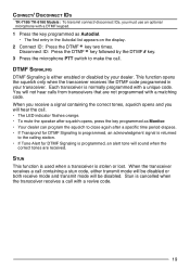
... the display. 2 Connect ID: Press the DTMF key two times. When the transceiver receives a call containing a stun code, either enabled or disabled by the DTMF # key. 3 Press the microphone PTT switch to the calling station. • If Tone Alert for DTMF Signaling is programmed, an acknowledgment signal is normally programmed with a unique code. When you receive a signal containing the correct tones, squelch opens and you must use an optional microphone...
... the display. 2 Connect ID: Press the DTMF key two times. When the transceiver receives a call containing a stun code, either enabled or disabled by the DTMF # key. 3 Press the microphone PTT switch to the calling station. • If Tone Alert for DTMF Signaling is programmed, an acknowledgment signal is normally programmed with a unique code. When you receive a signal containing the correct tones, squelch opens and you must use an optional microphone...


