
Instruction Manual
Page 2
... 8 Track/Disc Repeat 8 Track Scan 8 Random Play 8 Magazine Random Play 9 Switching Display 9 Menu system Menu System 10 Changing the Transmission Frequency 11 Modulation level 11 Dynamic control 11 Text Scroll 11 Basic Operations of remote 12 Installation Accessories 14 Installation Procedure 14 Installation 15 Connecting Wires to Terminals 17 Troubleshooting guide 18 Specifications 21 -2-
... 8 Track/Disc Repeat 8 Track Scan 8 Random Play 8 Magazine Random Play 9 Switching Display 9 Menu system Menu System 10 Changing the Transmission Frequency 11 Modulation level 11 Dynamic control 11 Text Scroll 11 Basic Operations of remote 12 Installation Accessories 14 Installation Procedure 14 Installation 15 Connecting Wires to Terminals 17 Troubleshooting guide 18 Specifications 21 -2-
Instruction Manual
Page 3
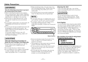
...8226; To prevent a short circuit when replacing a fuse, first disconnect the wiring harness. These may be a period after several hours, contact your CD player fogs up the volume level of hazardous radiation outside the unit. -3- Lens fogging In cold climates, there may be working order. • Be.... • Do not open the top or bottom cover. • Do not install the unit in your Kenwood dealer. The marking of a weaker class. The liquid crystal fluid may be reduced a little if the KDC-C521FM is used in places it is exposed to direct sunlight, high heat or humidity,...
...8226; To prevent a short circuit when replacing a fuse, first disconnect the wiring harness. These may be a period after several hours, contact your CD player fogs up the volume level of hazardous radiation outside the unit. -3- Lens fogging In cold climates, there may be working order. • Be.... • Do not open the top or bottom cover. • Do not install the unit in your Kenwood dealer. The marking of a weaker class. The liquid crystal fluid may be reduced a little if the KDC-C521FM is used in places it is exposed to direct sunlight, high heat or humidity,...
Instruction Manual
Page 6
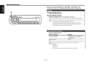
Selecting the Source Press the [SRC] button. CA-C1AX - Source required Display CD auto-changer Auxiliary input Off "CHANGER"/ "CHANGER-1"/ "CHANGER-2" "AUX" For Auxiliary input one of the below optional accessories is necessary. - The FM modulator is turned OFF and the radio can be heard. • Be sure to turn down the volume whenever you listen to... is switched into compact disc player's side. Turning OFF the Power Press the [SRC] button for more information on changing the transmission frequency. KCA-S210A - CD changer with an Auxiliary input function installed. -6-
Selecting the Source Press the [SRC] button. CA-C1AX - Source required Display CD auto-changer Auxiliary input Off "CHANGER"/ "CHANGER-1"/ "CHANGER-2" "AUX" For Auxiliary input one of the below optional accessories is necessary. - The FM modulator is turned OFF and the radio can be heard. • Be sure to turn down the volume whenever you listen to... is switched into compact disc player's side. Turning OFF the Power Press the [SRC] button for more information on changing the transmission frequency. KCA-S210A - CD changer with an Auxiliary input function installed. -6-
Instruction Manual
Page 14
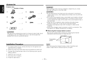
...screw, retain it carefully and attach it again before you start to install the unit, check first that nothing is installed, check whether the brake lamps, blinkers, wipers, etc. Reconnect the - Install the unit in the following order: ground, battery, ignition. 4.... Make the proper input and output wire connections for protecting the internal mechanism before transporting the unit again. 2. To prevent a short circuit, do not remove the caps on the other similar material. • Some disc changers...
...screw, retain it carefully and attach it again before you start to install the unit, check first that nothing is installed, check whether the brake lamps, blinkers, wipers, etc. Reconnect the - Install the unit in the following order: ground, battery, ignition. 4.... Make the proper input and output wire connections for protecting the internal mechanism before transporting the unit again. 2. To prevent a short circuit, do not remove the caps on the other similar material. • Some disc changers...
Instruction Manual
Page 15
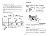
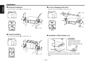
...and attach the other velcro to the parts where you wish to attach the display units. 5 Then, put velcros together and install the display units. • Installation using the trim mount plate 7 Display unit Attach one velcro to the slanted-line of the the display units as where it ... unit in the deformation of the case. • Depending on the installing location, the display unit may occur. Set both saides of the unit are not set according to the angle of installation of the CD auto changer. ■ Angle adjustment switches The angle adjustment switches on the both of ...
...and attach the other velcro to the parts where you wish to attach the display units. 5 Then, put velcros together and install the display units. • Installation using the trim mount plate 7 Display unit Attach one velcro to the slanted-line of the the display units as where it ... unit in the deformation of the case. • Depending on the installing location, the display unit may occur. Set both saides of the unit are not set according to the angle of installation of the CD auto changer. ■ Angle adjustment switches The angle adjustment switches on the both of ...
Instruction Manual
Page 16
... 1 0 45 90 90 45 0 ■ In case of FM modulator unit 6 2 2CAUTION Take sufficient care so that the wires are caught, they are not caught under the seat. If they may break. φ 3 3 Install the FM modulator unit beneath the front seat using φ 4 Metal fixture and Bind ...head screw as shown in the trunk Use the holes marked (¶) to install the unit. Bottom view 2 φ 4 3 φ 4 Side view 0 45...
... 1 0 45 90 90 45 0 ■ In case of FM modulator unit 6 2 2CAUTION Take sufficient care so that the wires are caught, they are not caught under the seat. If they may break. φ 3 3 Install the FM modulator unit beneath the front seat using φ 4 Metal fixture and Bind ...head screw as shown in the trunk Use the holes marked (¶) to install the unit. Bottom view 2 φ 4 3 φ 4 Side view 0 45...
Instruction Manual
Page 17
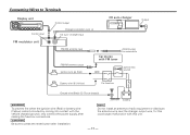
...CD auto-changer Output FM modulator unit FM/AM antenna input FM/AM antenna output Ignition wire + (Red) Car stereo with FM tuner Antenna plug for this unit. - 17 - Connecting Wires to press the reset button after making the fuse box connections. 2CAUTION Be sure to Terminals Display unit Control input Control output Changer... connection wire 4 CD auto - Battery NOTE Do not install an antenna of radio equipment or distribute the antenna wire near the changer output wire, for automobile ACC Ignition key switch ...
...CD auto-changer Output FM modulator unit FM/AM antenna input FM/AM antenna output Ignition wire + (Red) Car stereo with FM tuner Antenna plug for this unit. - 17 - Connecting Wires to press the reset button after making the fuse box connections. 2CAUTION Be sure to Terminals Display unit Control input Control output Changer... connection wire 4 CD auto - Battery NOTE Do not install an antenna of radio equipment or distribute the antenna wire near the changer output wire, for automobile ACC Ignition key switch ...


