

Instruction Manual
Page 30
...etc. Installation/connection Part list: A Faceplate 1) B Escutcheon 1) C Mounting sleeve 1) D Wiring harness 1) E Removal tool 2) F Flat head screw (for Nissan cars 4) G Round head screw (for Toyota cars 4) H Microphone (3 m) (KDC-X695 only 1) Basic procedure 1 Remove the key from the ignition switch, then disconnect the ...· terminal of the car battery. 2 Make proper input and output wire connections. \ (page 32) 3 Install the unit to...
...etc. Installation/connection Part list: A Faceplate 1) B Escutcheon 1) C Mounting sleeve 1) D Wiring harness 1) E Removal tool 2) F Flat head screw (for Nissan cars 4) G Round head screw (for Toyota cars 4) H Microphone (3 m) (KDC-X695 only 1) Basic procedure 1 Remove the key from the ignition switch, then disconnect the ...· terminal of the car battery. 2 Make proper input and output wire connections. \ (page 32) 3 Install the unit to...
Instruction Manual
Page 32
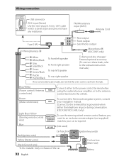
... (JASO) Antenna Cord Fuse (10A) Wiring harness D Rear output R L Front output Sub Woofer output Microphone H (KDC-X695 only) White White/Black Gray Gray/Black Green Green/Black Purple Purple/Black To front left speaker To front right speaker To rear left speaker To rear right speaker To Kenwood disc changer/ External optional accessory (To...
... (JASO) Antenna Cord Fuse (10A) Wiring harness D Rear output R L Front output Sub Woofer output Microphone H (KDC-X695 only) White White/Black Gray Gray/Black Green Green/Black Purple Purple/Black To front left speaker To front right speaker To rear left speaker To rear right speaker To Kenwood disc changer/ External optional accessory (To...

Instruction Manual
Page 33
Other wiring connection has been completed earlier. (page 32) 2 1 B A 2 Before attaching, make sure the direction of the escutcheon is correct. (Wider hooks on both sides of your ... the mounting sleeve and escutcheon B from the unit. 2 Align the holes in place. F ø5mm 8mm MAX. E B 12 A E C 3 English 33 Installing the unit 1 3 Connect the wiring harness to hold the mounting sleeve firmly in the unit (on the bottom side.) D 2 1 3 Dashboard of the escutcheon B, then pull it out. 3 Insert the removal tools...
Other wiring connection has been completed earlier. (page 32) 2 1 B A 2 Before attaching, make sure the direction of the escutcheon is correct. (Wider hooks on both sides of your ... the mounting sleeve and escutcheon B from the unit. 2 Align the holes in place. F ø5mm 8mm MAX. E B 12 A E C 3 English 33 Installing the unit 1 3 Connect the wiring harness to hold the mounting sleeve firmly in the unit (on the bottom side.) D 2 1 3 Dashboard of the escutcheon B, then pull it out. 3 Insert the removal tools...


