

User Manual
Page 4
... guide line displayed on the screen will not be different. Information The screen illustrations used in this condition) • Turn signal mode activated when user turn on the 360° Camera only. Using the 360° Camera / What is 360° Camera Driving Precautions The 360° Camera plays a subsidiary device in order to help driver checking surroundings around each camera is different, so light displayed on the Display Audio...
... guide line displayed on the screen will not be different. Information The screen illustrations used in this condition) • Turn signal mode activated when user turn on the 360° Camera only. Using the 360° Camera / What is 360° Camera Driving Precautions The 360° Camera plays a subsidiary device in order to help driver checking surroundings around each camera is different, so light displayed on the Display Audio...

User Manual
Page 8
... rear view mirrors. • When you reverse, some angles. however, mild staggered position of the left /right rear mirrors; When you drive, you to change of car mode are aligned due to temporarily disappear and drivers are precision device. To resume normal operations, image calibration and part replacement may not be required. 8 | 360° Camera Operations Manual Do not drive your car only by the display...
... rear view mirrors. • When you reverse, some angles. however, mild staggered position of the left /right rear mirrors; When you drive, you to change of car mode are aligned due to temporarily disappear and drivers are precision device. To resume normal operations, image calibration and part replacement may not be required. 8 | 360° Camera Operations Manual Do not drive your car only by the display...
User Manual
Page 9
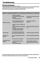
... under fluorescent lights, sodium lights, and mercury lights etc. Please have a problem with the 360° Camera, here are some discrepancy in a slope status. This is only for users' operating reference. 360° Camera Operations Manual | 9 Please check surroundings visually when reversing the car. Troubleshooting If You Notice Any Symptoms Troubleshooting will be some basic troubleshooting techniques that can help you to...
... under fluorescent lights, sodium lights, and mercury lights etc. Please have a problem with the 360° Camera, here are some discrepancy in a slope status. This is only for users' operating reference. 360° Camera Operations Manual | 9 Please check surroundings visually when reversing the car. Troubleshooting If You Notice Any Symptoms Troubleshooting will be some basic troubleshooting techniques that can help you to...

User Manual
Page 10
... dry with a dry cloth to protect your own screws. If it does not obstruct seat movement. battery. 2 Make the proper input and output wire connections for each unit. 3 Connect the wiring harness wires in the following precautions: • Make sure to ground the unit to a negative 12V DC power supply. • When replacing a fuse, only use goggles to prevent scratching the lens. NOTE • A rear view camera is a camera that...
... dry with a dry cloth to protect your own screws. If it does not obstruct seat movement. battery. 2 Make the proper input and output wire connections for each unit. 3 Connect the wiring harness wires in the following precautions: • Make sure to ground the unit to a negative 12V DC power supply. • When replacing a fuse, only use goggles to prevent scratching the lens. NOTE • A rear view camera is a camera that...

User Manual
Page 11
... unit is a danger of the car. • Do not perform installation in the rear view camera falling off . • Do not attach the camera bracket to areas on the fuse holder. • To minimize noise locate the TV antenna cable, radio antenna cable and RCA cable as far away from the side of the wiring short-circuiting to the vehicle body. • When replacing the fuse...
... unit is a danger of the car. • Do not perform installation in the rear view camera falling off . • Do not attach the camera bracket to areas on the fuse holder. • To minimize noise locate the TV antenna cable, radio antenna cable and RCA cable as far away from the side of the wiring short-circuiting to the vehicle body. • When replacing the fuse...

User Manual
Page 12
... series) is NOT compatible for this system. *Impossible to connect DRV-N520 (Dashcam) and KCA-2020AVM in parallel. (Either can be connected) Parts list Front/Rear camera section ECU Box Left/Right camera section 12 | Installation Manual (Others) • Full Wiring • Double side tape • Instruction manual • Calibration manual *To complete calibration easily, it is recommended to use calibration sheet. (Optional...
... series) is NOT compatible for this system. *Impossible to connect DRV-N520 (Dashcam) and KCA-2020AVM in parallel. (Either can be connected) Parts list Front/Rear camera section ECU Box Left/Right camera section 12 | Installation Manual (Others) • Full Wiring • Double side tape • Instruction manual • Calibration manual *To complete calibration easily, it is recommended to use calibration sheet. (Optional...
User Manual
Page 13
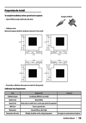
...below special tool is required. • 22mm Drill bit to make a hall in the side mirror Example of drill bit • Calibration sheet (Kenwood company handles it and please contact to it if you need) 0.4m 0.4m 2.2m 1.2m 2.2m 1.2m 0.6m...you make a calibration sheet, please be on the ceiling facing down. Installation Manual | 13 Wall Color Same as ground color. No angles to different cars model Pattern Color Black & White Ground Color Matte color, not reflective. Illumination Around 600 lux, white light Illumination Direction All lights should be noted for Install ...
...below special tool is required. • 22mm Drill bit to make a hall in the side mirror Example of drill bit • Calibration sheet (Kenwood company handles it and please contact to it if you need) 0.4m 0.4m 2.2m 1.2m 2.2m 1.2m 0.6m...you make a calibration sheet, please be on the ceiling facing down. Installation Manual | 13 Wall Color Same as ground color. No angles to different cars model Pattern Color Black & White Ground Color Matte color, not reflective. Illumination Around 600 lux, white light Illumination Direction All lights should be noted for Install ...
User Manual
Page 14
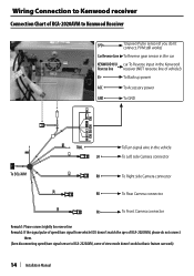
... Right side Camera connector RR To Rear Camera connector FR To Front Camera connector Remark1: Plrase connect rightly for reserse line Remark2: If the signal pulse of speed/turn signal from vehicle ECU doesn't match the spec of KCA-2020AVM, please do not connect them. (Even disconnecting speed/turn signal sensor to KCA-2020AVM, some of view mode doesn't work but basic feature can work) 14 | Installation Manual
... Right side Camera connector RR To Rear Camera connector FR To Front Camera connector Remark1: Plrase connect rightly for reserse line Remark2: If the signal pulse of speed/turn signal from vehicle ECU doesn't match the spec of KCA-2020AVM, please do not connect them. (Even disconnecting speed/turn signal sensor to KCA-2020AVM, some of view mode doesn't work but basic feature can work) 14 | Installation Manual
User Manual
Page 15
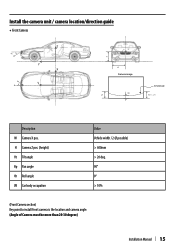
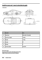
Install the camera unit / camera location/direction guide ◆ Front Camera θt θp Z Y X Y θr H W Camera image VB LH Vehicle body RH ≒ LH Description W Camera X pos. H Camera Z pos. (height) θt Tilt angle Θp Pan angle Θr Roll angle VB Car body occupation Value Vehicle width / 2 (if possible) > 600mm > 20 deg. 90° 0° > 10% (Front Camera section) Key point to install Front camera is the location and camera angle. (Angle of Camera must be more than 20-30 degree) Installation Manual | 15
Install the camera unit / camera location/direction guide ◆ Front Camera θt θp Z Y X Y θr H W Camera image VB LH Vehicle body RH ≒ LH Description W Camera X pos. H Camera Z pos. (height) θt Tilt angle Θp Pan angle Θr Roll angle VB Car body occupation Value Vehicle width / 2 (if possible) > 600mm > 20 deg. 90° 0° > 10% (Front Camera section) Key point to install Front camera is the location and camera angle. (Angle of Camera must be more than 20-30 degree) Installation Manual | 15
User Manual
Page 16
H Camera Z pos. (height) θt Tilt angle Θp Pan angle Θr Roll angle VB Car body occupation Value Vehicle width / 2 (if possible) > 600mm > 20 deg. 90° 0° around 10% (Rear Camera section) Key point to install Rear camera is the location and camera angle. (Angle of Camera must be more than 20-30 degree) 16 | Installation Manual Install the camera unit / camera location/direction guide ◆ Rear Camera Z Y X Y θr θt H θp LH W Camera image VB Vehicle body RH ≒ LH Description W Camera X pos.
H Camera Z pos. (height) θt Tilt angle Θp Pan angle Θr Roll angle VB Car body occupation Value Vehicle width / 2 (if possible) > 600mm > 20 deg. 90° 0° around 10% (Rear Camera section) Key point to install Rear camera is the location and camera angle. (Angle of Camera must be more than 20-30 degree) 16 | Installation Manual Install the camera unit / camera location/direction guide ◆ Rear Camera Z Y X Y θr θt H θp LH W Camera image VB Vehicle body RH ≒ LH Description W Camera X pos.
User Manual
Page 17
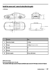
Install the camera unit / camera location/direction guide ◆ Left Camera Z θr Y X Y θp θt H Camera image VB RH Vehicle body FH ≒ RH Description H Camera Z pos. (height) θt Tilt angle Θp Pan angle Θr Roll angle VB Car body occupation Value > 600mm > 20 deg. (45 degree is better) 95° 5° 10% one-third is better (Right Camera section) Key point to install Right camera is the angle. *Be careful for Θt(Tilt Angle: must be 20 degree) and Θp(Pan angle: must be 90-100 degree, the best is 95 degree) Installation Manual | 17
Install the camera unit / camera location/direction guide ◆ Left Camera Z θr Y X Y θp θt H Camera image VB RH Vehicle body FH ≒ RH Description H Camera Z pos. (height) θt Tilt angle Θp Pan angle Θr Roll angle VB Car body occupation Value > 600mm > 20 deg. (45 degree is better) 95° 5° 10% one-third is better (Right Camera section) Key point to install Right camera is the angle. *Be careful for Θt(Tilt Angle: must be 20 degree) and Θp(Pan angle: must be 90-100 degree, the best is 95 degree) Installation Manual | 17
User Manual
Page 18
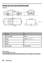
Install the camera unit / camera location/direction guide ◆ Right Camera Z θr Y X Y θp θt H Camera image VB FH Vehicle body RH ≒ FH Description H Camera Z pos. (height) θt Tilt angle Θp Pan angle Θr Roll angle VB Car body occupation Value > 600mm > 20 deg. (45 degree is better) 95° 5° 10% one-third is better (Left Camera section) Key point to install Left camera is the angle. *Be careful for Θt(Tilt Angle: must be 20 degree) and Θp(Pan angle: must be 90-100 degree, the best is 95 degree) 18 | Installation Manual
Install the camera unit / camera location/direction guide ◆ Right Camera Z θr Y X Y θp θt H Camera image VB FH Vehicle body RH ≒ FH Description H Camera Z pos. (height) θt Tilt angle Θp Pan angle Θr Roll angle VB Car body occupation Value > 600mm > 20 deg. (45 degree is better) 95° 5° 10% one-third is better (Left Camera section) Key point to install Left camera is the angle. *Be careful for Θt(Tilt Angle: must be 20 degree) and Θp(Pan angle: must be 90-100 degree, the best is 95 degree) 18 | Installation Manual

User Manual
Page 19
Front Camera(FR) assembly installation Lock with Ø3 Self-tapping screw on car's front air dam with adhesive tape on the button of camera Suitable camera angle 20~30degree Installation Manual | 19 Angle lock screw Each graduation is 15 degree Angle adjust screw Pigtail wiring of BKT.
Front Camera(FR) assembly installation Lock with Ø3 Self-tapping screw on car's front air dam with adhesive tape on the button of camera Suitable camera angle 20~30degree Installation Manual | 19 Angle lock screw Each graduation is 15 degree Angle adjust screw Pigtail wiring of BKT.

User Manual
Page 20
Rear Camera (RR) assembly installation(Horizontal mount installation) Be sure to lock the screw after the angle fixed. 25~30 degree 43mm 44mm Remark: all the screws on BKT are coated NYLOK paint to prevent loosening Angle adjust screw Angle lock screw This BKT for horizontal installation 20 | In(bsrteaallcahtidonowMna)nual Each graduation is 15 degree As well as Front Camera installation, Camera angle must be 25-30 degree.
Rear Camera (RR) assembly installation(Horizontal mount installation) Be sure to lock the screw after the angle fixed. 25~30 degree 43mm 44mm Remark: all the screws on BKT are coated NYLOK paint to prevent loosening Angle adjust screw Angle lock screw This BKT for horizontal installation 20 | In(bsrteaallcahtidonowMna)nual Each graduation is 15 degree As well as Front Camera installation, Camera angle must be 25-30 degree.

User Manual
Page 21
... from horizontal to vertical. Installation Manual | 21 Besuretolockthe screw after the angle fixed. Rear Camera(RR)assembly installation(vertical mount installation) For some car which we can not install rear-camera with horizontal mount How to change This BKT for horizontal installation (breach down) Screw remove Be sure to install vertical mount by changing the bracket location. Example: Impossible to install with horizontal mount of bracket, it is...
... from horizontal to vertical. Installation Manual | 21 Besuretolockthe screw after the angle fixed. Rear Camera(RR)assembly installation(vertical mount installation) For some car which we can not install rear-camera with horizontal mount How to change This BKT for horizontal installation (breach down) Screw remove Be sure to install vertical mount by changing the bracket location. Example: Impossible to install with horizontal mount of bracket, it is...
User Manual
Page 23
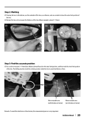
Step 2: Marking #1:Pressing the lens to the bottom, use the outerside of the lens as a reference, and use a marker to draw the outer limit position of the lens. #2.Remove the lens set to measure the thickness of the lens.(Above example is very important. The drilling must be ...position, and then mark the inner limit position of back mirror, this measurement process is about 9~10mm) #1 #2 Step 3: Find the accurate position #3:Use a ruler to avoid interference of lens. #3 Mirror movable area Mirror movable area (with thickness of mirror) (w/o thickness of mirror) Remarks: To avoid...
Step 2: Marking #1:Pressing the lens to the bottom, use the outerside of the lens as a reference, and use a marker to draw the outer limit position of the lens. #2.Remove the lens set to measure the thickness of the lens.(Above example is very important. The drilling must be ...position, and then mark the inner limit position of back mirror, this measurement process is about 9~10mm) #1 #2 Step 3: Find the accurate position #3:Use a ruler to avoid interference of lens. #3 Mirror movable area Mirror movable area (with thickness of mirror) (w/o thickness of mirror) Remarks: To avoid...

User Manual
Page 24
...rear mirrors (the rear mirrors need to be same. #5-1 #5-2 Drill holes after finding the suit able location of side camera and if some of the rib or wall (inside mirror housing) interferes to make... a hall in the housing (Drill bit is NOT included in this wall if you can not place side camera correctly. Step 4: Cut the rib or wall inside the mirror housing #4-1/#4-2:after vertical fixation Drill holes on the bottom cover, the hole diameter Ø22mm, Use 22mm drill bit to install... its camera, please cut and remove them. #4-1 #4-2 Remove this...
...rear mirrors (the rear mirrors need to be same. #5-1 #5-2 Drill holes after finding the suit able location of side camera and if some of the rib or wall (inside mirror housing) interferes to make... a hall in the housing (Drill bit is NOT included in this wall if you can not place side camera correctly. Step 4: Cut the rib or wall inside the mirror housing #4-1/#4-2:after vertical fixation Drill holes on the bottom cover, the hole diameter Ø22mm, Use 22mm drill bit to install... its camera, please cut and remove them. #4-1 #4-2 Remove this...

User Manual
Page 26
Connector from Camera unit 26 | Installation Manual Connector from ECU Step 7: Confirm side camera direction Before completing re-assemble mirror unit, confirm camera unit faces right direction. Step 8: Connect the wire to the receiver When the whole line is out of 20-45 degrees, Auto calibration might be connected to be done, or please complete it by manual calibration. Check the configtation page (P16-17) This...
Connector from Camera unit 26 | Installation Manual Connector from ECU Step 7: Confirm side camera direction Before completing re-assemble mirror unit, confirm camera unit faces right direction. Step 8: Connect the wire to the receiver When the whole line is out of 20-45 degrees, Auto calibration might be connected to be done, or please complete it by manual calibration. Check the configtation page (P16-17) This...

User Manual
Page 38
4 Select Car Dimension 1 Must at P / N / D Mode then touch area "A" three times. A 2.Use ← and → to select the car you want to install 2 Calibration interface. 3 Select Car Dimension 1.Please touch "Car Dimension" 38 |Calibration Manual 3.Choose car model (1)Select the car model you want to install (2)After selecting, please press Back (3)When you press Back icon one second, then system will re-start and then load in vehicle size you choose. 1 2
4 Select Car Dimension 1 Must at P / N / D Mode then touch area "A" three times. A 2.Use ← and → to select the car you want to install 2 Calibration interface. 3 Select Car Dimension 1.Please touch "Car Dimension" 38 |Calibration Manual 3.Choose car model (1)Select the car model you want to install (2)After selecting, please press Back (3)When you press Back icon one second, then system will re-start and then load in vehicle size you choose. 1 2

User Manual
Page 40
.... 1.Confirm that the connectors are properly installed. 2.Confirm that the wire is not damaged. 3.Make sure the camera is not malfunctioning. 2 Blurred image. 1.Confirm removal of camera protector. 2.Make sure the camera is incorrect. Manually adjust the feature point. 40 |Calibration Manual Please clean the calibration pattern. 5 Reflective. 6 Detected feature point is not dirty. 3.Make sure the camera has...
.... 1.Confirm that the connectors are properly installed. 2.Confirm that the wire is not damaged. 3.Make sure the camera is not malfunctioning. 2 Blurred image. 1.Confirm removal of camera protector. 2.Make sure the camera is incorrect. Manually adjust the feature point. 40 |Calibration Manual Please clean the calibration pattern. 5 Reflective. 6 Detected feature point is not dirty. 3.Make sure the camera has...


