Instruction Manual
Page 1
... operation procedures will help you call upon your records Record the serial number, found on the back of the unit, in the spaces designated on the product. For your Kenwood dealer for information or service on the warranty card, and in the space provided below. Refer to read through this instruction manual. KDC-132 KDC-1032 KDC-132CR CD-RECEIVER INSTRUCTION MANUAL Take the time to the model...
... operation procedures will help you call upon your records Record the serial number, found on the back of the unit, in the spaces designated on the product. For your Kenwood dealer for information or service on the warranty card, and in the space provided below. Refer to read through this instruction manual. KDC-132 KDC-1032 KDC-132CR CD-RECEIVER INSTRUCTION MANUAL Take the time to the model...
Instruction Manual
Page 2
... Notes About CDs General features Power Selecting the Source Volume Attenuator System Q Audio Control Audio Setup Speaker Setting Clock Display Adjusting Clock Theft Deterrent Faceplate Tuner features Tuning Tuning Mode Station Preset Memory Auto Memory Entry Preset Tuning CRSC (Clean Reception System Circuit) CD player features Playing CD Fast Forwarding and Reversing Track Search Track Repeat Scan Play Random Play 3 Accessories/ Installation Procedure 15 4 Connecting Wires to Terminals 16 5 Installation 17 6 Removing the Unit 19 7 Troubleshooting Guide 20 Specifications 22 11...
... Notes About CDs General features Power Selecting the Source Volume Attenuator System Q Audio Control Audio Setup Speaker Setting Clock Display Adjusting Clock Theft Deterrent Faceplate Tuner features Tuning Tuning Mode Station Preset Memory Auto Memory Entry Preset Tuning CRSC (Clean Reception System Circuit) CD player features Playing CD Fast Forwarding and Reversing Track Search Track Repeat Scan Play Random Play 3 Accessories/ Installation Procedure 15 4 Connecting Wires to Terminals 16 5 Installation 17 6 Removing the Unit 19 7 Troubleshooting Guide 20 Specifications 22 11...
Instruction Manual
Page 3
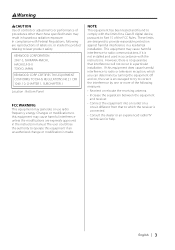
... approved in the instruction manual. KENWOOD CORPORATION 2967-3, ISHIKAWA-MACHI, HACHIOJI-SHI TOKYO, JAPAN KENWOOD CORP. The user could lose the authority to this equipment if an unauthorized change or modification is no guarantee that to provide reasonable protection against harmful interference in a particular installation. However, there is made. Changes or modifications to operate this equipment may generate or use radio frequency energy.
... approved in the instruction manual. KENWOOD CORPORATION 2967-3, ISHIKAWA-MACHI, HACHIOJI-SHI TOKYO, JAPAN KENWOOD CORP. The user could lose the authority to this equipment if an unauthorized change or modification is no guarantee that to provide reasonable protection against harmful interference in a particular installation. However, there is made. Changes or modifications to operate this equipment may generate or use radio frequency energy.
Instruction Manual
Page 4
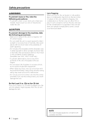
... lens in the CD player of precision equipment. • When replacing a fuse, only use the wrong screws, you try to load a 3 in . In such a situation, remove the disc and wait for the condensation to evaporate. Also avoid places with the prescribed rating. CDs in the CD slot If you could damage the unit. CD with its adapter into the unit, the adapter might separate...
... lens in the CD player of precision equipment. • When replacing a fuse, only use the wrong screws, you try to load a 3 in . In such a situation, remove the disc and wait for the condensation to evaporate. Also avoid places with the prescribed rating. CDs in the CD slot If you could damage the unit. CD with its adapter into the unit, the adapter might separate...
Instruction Manual
Page 5
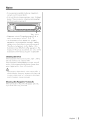
... LCD may affect its mechanical parts. Cleaning the Faceplate Terminals If the terminals on the display may scratch the surface or erases characters. Notes • If you experience problems during installation, consult your Kenwood dealer. • If the unit fails to explain more clearly how the controls are used. The unit returns to factory settings when the Reset button is stained badly, wipe the...
... LCD may affect its mechanical parts. Cleaning the Faceplate Terminals If the terminals on the display may scratch the surface or erases characters. Notes • If you experience problems during installation, consult your Kenwood dealer. • If the unit fails to explain more clearly how the controls are used. The unit returns to factory settings when the Reset button is stained badly, wipe the...
Instruction Manual
Page 6
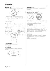
... play discs which do not have the mark. • You cannot play the CDs with tape stuck on the package etc. • Do not stick tape etc. Removing CDs When removing CDs from the center of the CD. CDs that cannot be used . • This unit can only play A CD-R or CD-RW that are easier to your CD-R/CD-RW writing software, and your CDR/CD-RW recorder instruction manual...
... play discs which do not have the mark. • You cannot play the CDs with tape stuck on the package etc. • Do not stick tape etc. Removing CDs When removing CDs from the center of the CD. CDs that cannot be used . • This unit can only play A CD-R or CD-RW that are easier to your CD-R/CD-RW writing software, and your CDR/CD-RW recorder instruction manual...
Instruction Manual
Page 7
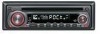
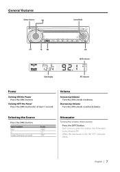
... time you press the button, the Attenuator turns ON and OFF. Decreasing Volume Turn the [VOL] knob counterclockwise. Volume Increasing Volume Turn the [VOL] knob clockwise. Turning OFF the Power Press the [SRC] button for at least 1 second. Selecting the Source Press the [SRC] button. Source required Tuner CD Standby (Illumination only mode) Display "TUnE" "CD" "STBY" Attenuator Turning the volume down quickly. English | 7 General features Release button VOL Control knob ATT Q SRC CLK LOUD indicator Clock display ATT...
... time you press the button, the Attenuator turns ON and OFF. Decreasing Volume Turn the [VOL] knob counterclockwise. Volume Increasing Volume Turn the [VOL] knob clockwise. Turning OFF the Power Press the [SRC] button for at least 1 second. Selecting the Source Press the [SRC] button. Source required Tuner CD Standby (Illumination only mode) Display "TUnE" "CD" "STBY" Attenuator Turning the volume down quickly. English | 7 General features Release button VOL Control knob ATT Q SRC CLK LOUD indicator Clock display ATT...
Instruction Manual
Page 8
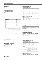
..." Rear 15 - Front 15 Exit Audio Control mode (Volume control mode) 5 Exit Audio Control mode Press any button. Adjustment Item Display Volume offset "V-OF" Loudness "LOUD" Range -8 - ±0 ON/OFF • Volume offset: Sets each setting value with the Speaker setting. When Loudness is ON, "LOUD" indicator is displayed. When the System Q setting is changed, the Bass, Middle, and Treble set in the table below . 4 Adjust the Audio setup item Turn the [VOL] knob. Audio Control 1 Select the source to adjust Press the [SRC] button...
..." Rear 15 - Front 15 Exit Audio Control mode (Volume control mode) 5 Exit Audio Control mode Press any button. Adjustment Item Display Volume offset "V-OF" Loudness "LOUD" Range -8 - ±0 ON/OFF • Volume offset: Sets each setting value with the Speaker setting. When Loudness is ON, "LOUD" indicator is displayed. When the System Q setting is changed, the Bass, Middle, and Treble set in the table below . 4 Adjust the Audio setup item Turn the [VOL] knob. Audio Control 1 Select the source to adjust Press the [SRC] button...

Instruction Manual
Page 9
... setting alternates between the settings shown in the table below. Select the "STBY" display. 2 Enter Speaker Setting mode Press the [VOL] knob. 3 Select the Speaker type Turn the [VOL] knob. The clock display blinks. 4 Adjust the hours Push the Control knob towards [4] or [¢]. 5 Exit clock adjustment mode Press the [CLK] button. Speaker type OFF For 5 & 4 in . Each time you press the button, the clock display turns ON and OFF. Clock Display Press the [CLK] button. Speaker Setting Fine-tuning...
... setting alternates between the settings shown in the table below. Select the "STBY" display. 2 Enter Speaker Setting mode Press the [VOL] knob. 3 Select the Speaker type Turn the [VOL] knob. The clock display blinks. 4 Adjust the hours Push the Control knob towards [4] or [¢]. 5 Exit clock adjustment mode Press the [CLK] button. Speaker type OFF For 5 & 4 in . Each time you press the button, the clock display turns ON and OFF. Clock Display Press the [CLK] button. Speaker Setting Fine-tuning...
Instruction Manual
Page 10
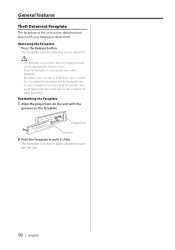
... unit. 10 | English Removing the Faceplate Press the Release button. General features Theft Deterrent Faceplate The faceplate of the unit can be detached and taken with you, helping to deter theft. The faceplate is a precision piece of water splashing. Projections Grooves 2 Push the faceplate in until it . • The faceplate is locked in its faceplate case while detached. (Faceplate case : Accessory of the KDC-1032...
... unit. 10 | English Removing the Faceplate Press the Release button. General features Theft Deterrent Faceplate The faceplate of the unit can be detached and taken with you, helping to deter theft. The faceplate is a precision piece of water splashing. Projections Grooves 2 Push the faceplate in until it . • The faceplate is locked in its faceplate case while detached. (Faceplate case : Accessory of the KDC-1032...
Instruction Manual
Page 11
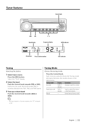
... switches between the modes shown in the Preset memory. English | 11 Tuner features Control knob CRSC SRC Band display 1 - 6 Frequency display AUTO indicator ST indicator Preset station number CRSC indicator Tuning Selecting the station. 1 Select tuner source Press the [SRC] button. Search in order of stereo stations the "ST" indicator is ON. Normal manual tuning control. • During reception of the stations in the table below. Select the "TUnE" display. 2 Select the band Push the Control knob towards [4] or [¢]. Each time...
... switches between the modes shown in the Preset memory. English | 11 Tuner features Control knob CRSC SRC Band display 1 - 6 Frequency display AUTO indicator ST indicator Preset station number CRSC indicator Tuning Selecting the station. 1 Select tuner source Press the [SRC] button. Search in order of stereo stations the "ST" indicator is ON. Normal manual tuning control. • During reception of the stations in the table below. Select the "TUnE" display. 2 Select the band Push the Control knob towards [4] or [¢]. Each time...

Instruction Manual
Page 12
.... Auto Memory Entry Putting stations with good reception in the memory. 1 Select the band Push the Control knob towards [FM] or [AM]. 2 Recall the station Press the desired [1] - [6] button. 12 | English When 6 stations that can be received are put in the memory Auto Memory Entry closes. On each band, 1 station can be put in the memory on each [1] - [6] button. The preset number display blinks 1 time. Tuner features Station Preset Memory Putting a station in the memory. 1 Select the...
.... Auto Memory Entry Putting stations with good reception in the memory. 1 Select the band Push the Control knob towards [FM] or [AM]. 2 Recall the station Press the desired [1] - [6] button. 12 | English When 6 stations that can be received are put in the memory Auto Memory Entry closes. On each band, 1 station can be put in the memory on each [1] - [6] button. The preset number display blinks 1 time. Tuner features Station Preset Memory Putting a station in the memory. 1 Select the...
Instruction Manual
Page 13
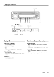
... number IN indicator Track time Playing CD When a disc is ON. Release your finger to play Press the Control knob. English | 13 Pause and play the disc at that point. Each time you press the knob, the audio pauses or plays. Eject the CD Press the [0] button. Reversing Hold down toward [4] with the Control knob. Release your finger to play the disc at that point. Select the "CD" display. • When a CD...
... number IN indicator Track time Playing CD When a disc is ON. Release your finger to play Press the Control knob. English | 13 Pause and play the disc at that point. Each time you press the knob, the audio pauses or plays. Eject the CD Press the [0] button. Reversing Hold down toward [4] with the Control knob. Release your finger to play the disc at that point. Select the "CD" display. • When a CD...
Instruction Manual
Page 14
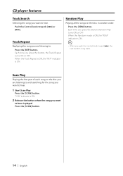
... Play Press the [SCAN] button. Scan Play Playing the first part of each song on the disc in random order. Each time you want to . When the Random mode is ON, the "RDM" indicator is ON. "SCN" indicator is played Press the [SCAN] button. 14 | English Press the [RDM] button. CD player features Track Search Selecting the song you press the button, the Track Repeat turns...
... Play Press the [SCAN] button. Scan Play Playing the first part of each song on the disc in random order. Each time you want to . When the Random mode is ON, the "RDM" indicator is ON. "SCN" indicator is played Press the [SCAN] button. 14 | English Press the [RDM] button. CD player features Track Search Selecting the song you press the button, the Track Repeat turns...
Instruction Manual
Page 15
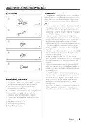
... the - Connect the wiring harness wires in your car's ignition does not have been activated. English | 15 battery. 8. Always connect those wires to work if you connect the ignition wire to a power source with a constant voltage supply, as with vinyl tape or other similar material. Make the proper input and output wire connections for each unit. 3. The unit may be checked. • If your car. 7. Accessories/ Installation Procedure Accessories 1 2 3 4 5 ..........1 ..........2 ..........4 ..........4 ..........1 Installation Procedure 1. Connect the speaker wires of...
... the - Connect the wiring harness wires in your car's ignition does not have been activated. English | 15 battery. 8. Always connect those wires to work if you connect the ignition wire to a power source with a constant voltage supply, as with vinyl tape or other similar material. Make the proper input and output wire connections for each unit. 3. The unit may be checked. • If your car. 7. Accessories/ Installation Procedure Accessories 1 2 3 4 5 ..........1 ..........2 ..........4 ..........4 ..........1 Installation Procedure 1. Connect the speaker wires of...
Instruction Manual
Page 16
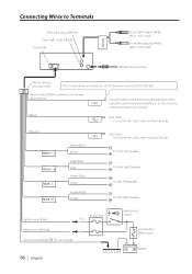
Battery Power control/Motor antenna control wire (Blue/White) P.CONT Connect either to the power control terminal when using the optional power amplifier, or to Terminals Rear left output (White) Rear right output (Red) Fuse (10A) FRONT Front right output (Red) (KDC-1032 only) Front left speaker To rear right speaker Ignition wire (Red) Car fuse box ACC Battery wire (Yellow) Ground wire (Black) · (To car chassis) 16 | English + Ignition key switch Car fuse box (Main fuse) - CONT Not Used Do not let the wire come out...
Battery Power control/Motor antenna control wire (Blue/White) P.CONT Connect either to the power control terminal when using the optional power amplifier, or to Terminals Rear left output (White) Rear right output (Red) Fuse (10A) FRONT Front right output (Red) (KDC-1032 only) Front left speaker To rear right speaker Ignition wire (Red) Car fuse box ACC Battery wire (Yellow) Ground wire (Black) · (To car chassis) 16 | English + Ignition key switch Car fuse box (Main fuse) - CONT Not Used Do not let the wire come out...
Instruction Manual
Page 17
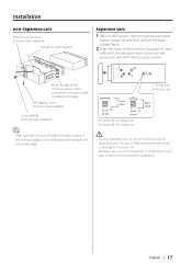
... it may malfunction (for Toyota car • Make sure that the unit is used with the accessory screws. English | 17 Accessory3...for Nissan car Accessory4...for example, the sound may occur if a screwdriver or similar tool is installed securely in the unit (two locations on each side) with the vehicle mounting bracket and secure the unit with excessive force during the...
... it may malfunction (for Toyota car • Make sure that the unit is used with the accessory screws. English | 17 Accessory3...for Nissan car Accessory4...for example, the sound may occur if a screwdriver or similar tool is installed securely in the unit (two locations on each side) with the vehicle mounting bracket and secure the unit with excessive force during the...
Instruction Manual
Page 20
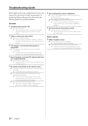
...'s a source you can't switch. ✔ There's no media in this unit, you want to listen to. No sound can 't switch to each output terminal is connected to a different speaker. ? Troubleshooting Guide What might seem to be a malfunction in your unit may just be heard, or the volume is low. ✔ The fader or balance settings are set all the way. ✔ The antenna control wire is not connected. ☞ Connect...
...'s a source you can't switch. ✔ There's no media in this unit, you want to listen to. No sound can 't switch to each output terminal is connected to a different speaker. ? Troubleshooting Guide What might seem to be a malfunction in your unit may just be heard, or the volume is low. ✔ The fader or balance settings are set all the way. ✔ The antenna control wire is not connected. ☞ Connect...
Instruction Manual
Page 21
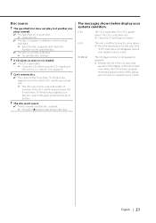
.... The CD is scratched a lot. ➪ Clean the CD and load it is loaded. ✔ The CD is that specified. ☞ Eject the disc magazine and check the number for some reason. ➪ Press the reset button on (page 6). ? Disc source ? The specified disc does not play, but another disc inserted. ☞ Press the [0] button and remove the disc. The messages shown below display your nearest service center...
.... The CD is scratched a lot. ➪ Clean the CD and load it is loaded. ✔ The CD is that specified. ☞ Eject the disc magazine and check the number for some reason. ➪ Press the reset button on (page 6). ? Disc source ? The specified disc does not play, but another disc inserted. ☞ Press the [0] button and remove the disc. The messages shown below display your nearest service center...
Instruction Manual
Page 22
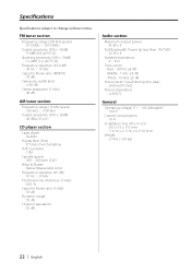
... Channel separation : 85 dB Audio section Maximum output power : 45 W x 4 Full Bandwidth Power (at less than 1% THD) : 22 W x 4 Speaker impedance : 4 - 8 Ω Tone action Bass : 100 Hz ±8 dB Middle : 1 kHz ±8 dB Treble : 10 kHz ±8 dB Preout level / Load (during disc play) : 2000 mV/10 kΩ Preout impedance : ≤ 600 Ω General Operating voltage (11 - 16V allowable) : 14.4 V Current consumption : 10 A Installation...
... Channel separation : 85 dB Audio section Maximum output power : 45 W x 4 Full Bandwidth Power (at less than 1% THD) : 22 W x 4 Speaker impedance : 4 - 8 Ω Tone action Bass : 100 Hz ±8 dB Middle : 1 kHz ±8 dB Treble : 10 kHz ±8 dB Preout level / Load (during disc play) : 2000 mV/10 kΩ Preout impedance : ≤ 600 Ω General Operating voltage (11 - 16V allowable) : 14.4 V Current consumption : 10 A Installation...


