Instruction Manual
Page 4
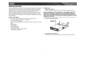
...radio (screwdriver, socket wrench set or other tools) • Electrical tape • Crimping tool • Volt meter/test light • Crimp connections • 18 gauge wire for installation in a car equipped with an onboard drive or navigation computer, do not disconnect the battery cable. Remove Transport Screws TRANSPORT SCREWS HALF SLEEVE... specialty shops. Remove Radio from 9:00am to 6:00pm EST Monday through Friday. INSTALLATION This unit is designed for power connections • 16-18 gauge speaker wire MP6212 Preparation 1. NOTE: If the MP6212 is to the dashboard.
...radio (screwdriver, socket wrench set or other tools) • Electrical tape • Crimping tool • Volt meter/test light • Crimp connections • 18 gauge wire for installation in a car equipped with an onboard drive or navigation computer, do not disconnect the battery cable. Remove Transport Screws TRANSPORT SCREWS HALF SLEEVE... specialty shops. Remove Radio from 9:00am to 6:00pm EST Monday through Friday. INSTALLATION This unit is designed for power connections • 16-18 gauge speaker wire MP6212 Preparation 1. NOTE: If the MP6212 is to the dashboard.
Instruction Manual
Page 5
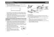
...the unit does not operate, re-check all connections are secure and insulated with the kit. 1. MP6212 Using the Mounting Sleeve 1. Do not force the sleeve into place. 6. Check for sufficient space ...to attach the radio to the instructions in the Universal Installation instruc- See "Wiring" on ). After completing the wiring connections, turn the unit on to the radio and dashboard as necessary until...the sleeve easily slides into position, use of horizontal. Secure the rear of the CD player, the chassis must be on page 5. tions. 2. Attach the support strap to ...
...the unit does not operate, re-check all connections are secure and insulated with the kit. 1. MP6212 Using the Mounting Sleeve 1. Do not force the sleeve into place. 6. Check for sufficient space ...to attach the radio to the instructions in the Universal Installation instruc- See "Wiring" on ). After completing the wiring connections, turn the unit on to the radio and dashboard as necessary until...the sleeve easily slides into position, use of horizontal. Secure the rear of the CD player, the chassis must be on page 5. tions. 2. Attach the support strap to ...
Instruction Manual
Page 6
... the front of the new radio chassis. If removal keys are inserted at 1-800-323-4815 from 9:00am to the new radio. MP6212 Technical Assistance If you require assistance, contact Technical Support at an angle, they will not lock properly and will be used to the ... of installation. 1. Remove the factory mounting brackets and hardware from either side. Using an incorrect fuse could damage the radio. Reconnect Battery When wiring is the correct type and amperage. Fuses When replacing a fuse, make sure the new fuse is complete, reconnect the battery negative terminal. Mount...
... the front of the new radio chassis. If removal keys are inserted at 1-800-323-4815 from 9:00am to the new radio. MP6212 Technical Assistance If you require assistance, contact Technical Support at an angle, they will not lock properly and will be used to the ... of installation. 1. Remove the factory mounting brackets and hardware from either side. Using an incorrect fuse could damage the radio. Reconnect Battery When wiring is the correct type and amperage. Fuses When replacing a fuse, make sure the new fuse is complete, reconnect the battery negative terminal. Mount...
Instruction Manual
Page 7
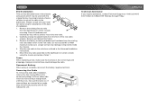
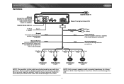
... for use with four speakers. NOTE: Only connect speakers with a nominal impedance of wire. Memory/Battery Connect to existing radio wire or radio fuse. Accessory/Ignition Connect to battery or 12 volt power source that is not connected. MP6212 WIRING Antenna Connect the antenna plug from the existing antenna cable (some vehicles require an...
... for use with four speakers. NOTE: Only connect speakers with a nominal impedance of wire. Memory/Battery Connect to existing radio wire or radio fuse. Accessory/Ignition Connect to battery or 12 volt power source that is not connected. MP6212 WIRING Antenna Connect the antenna plug from the existing antenna cable (some vehicles require an...
Instruction Manual
Page 10
...the default display. Beep Tone The beep tone feature allows the selection of the chassis and can only be activated upon initial installation after all wiring is complete or if there is located on the unit. Press the DISP button to set the minutes. Reset Button The RESET button is ...12/24 HOUR, VOL LAST/VOL ADJ, BEEP ON/ OFF, AREA SET, LO/DX. Press the MENU button (5) to the unit's audio output signal. MP6212 Frequency Spacing This option allows you have already accessed the menu. NOTE: Distant mode is activated, the most recently selected bass and treble levels. is...
...the default display. Beep Tone The beep tone feature allows the selection of the chassis and can only be activated upon initial installation after all wiring is complete or if there is located on the unit. Press the DISP button to set the minutes. Reset Button The RESET button is ...12/24 HOUR, VOL LAST/VOL ADJ, BEEP ON/ OFF, AREA SET, LO/DX. Press the MENU button (5) to the unit's audio output signal. MP6212 Frequency Spacing This option allows you have already accessed the menu. NOTE: Distant mode is activated, the most recently selected bass and treble levels. is...
Instruction Manual
Page 21
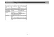
MP6212 TROUBLESHOOTING Problem Does not operate (display does not light) No power to unit No speakers operate (display lights normally) Not all splices and connections Speaker wires shorting Check splices; check speaker wires Incorrect splices or connections Check all speakers operate Blows fuses Cause No power to yellow wire... fuse; insulate all to chassis ground or to bare wires each other Power wire shorting to Make sure wire is not pinched ground Speaker wires shorting Make sure wire is not pinched to red wire Inline fuse blown Inline fuse blown Speaker harness not connected...
MP6212 TROUBLESHOOTING Problem Does not operate (display does not light) No power to unit No speakers operate (display lights normally) Not all splices and connections Speaker wires shorting Check splices; check speaker wires Incorrect splices or connections Check all speakers operate Blows fuses Cause No power to yellow wire... fuse; insulate all to chassis ground or to bare wires each other Power wire shorting to Make sure wire is not pinched ground Speaker wires shorting Make sure wire is not pinched to red wire Inline fuse blown Inline fuse blown Speaker harness not connected...


