Owners Manual
Page 1
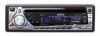
... by phone at 1-800-323-4815. Preparation 1 Wiring 3 Installation 5 Operation 6 Tuner Operation 13 CD Player Operation 15 CD Changer Operation 16 Remote Control 16 MP3/WMA Operation 17 Troubleshooting 22 Specifications 22 Warranty 22 Preparation Getting Started It's a good idea to read all the features of your new Jensen receiver for power connections • 16-18 gauge speaker wire Speaker Requirements: Only connect speakers rated in this owner's manual clear and easy to remove existing radio (screwdriver, socket wrench set or...
... by phone at 1-800-323-4815. Preparation 1 Wiring 3 Installation 5 Operation 6 Tuner Operation 13 CD Player Operation 15 CD Changer Operation 16 Remote Control 16 MP3/WMA Operation 17 Troubleshooting 22 Specifications 22 Warranty 22 Preparation Getting Started It's a good idea to read all the features of your new Jensen receiver for power connections • 16-18 gauge speaker wire Speaker Requirements: Only connect speakers rated in this owner's manual clear and easy to remove existing radio (screwdriver, socket wrench set or...
Owners Manual
Page 3
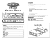
... battery or to the existing radio wire or radio fuse. 5. Connect to a 12 volt power source that is the correct type and amperage. Splice or crimp wires. 2. Wiring Diagram / Color Codes 1. Accessory/Ignition (red wire) - RCA Outputs to the ground terminal or a clean, unpainted part of wire. 2. Antenna 12. Right front speaker 7. Left rear spearker 8. Auxiliary Input Cable (yellow) 11. Connect to Amplifier 10. Left front speaker 6. CD Changer Fuses When replacing a fuse, make all these connections without even being in the radio opening. 4. Connect...
... battery or to the existing radio wire or radio fuse. 5. Connect to a 12 volt power source that is the correct type and amperage. Splice or crimp wires. 2. Wiring Diagram / Color Codes 1. Accessory/Ignition (red wire) - RCA Outputs to the ground terminal or a clean, unpainted part of wire. 2. Antenna 12. Right front speaker 7. Left rear spearker 8. Auxiliary Input Cable (yellow) 11. Connect to Amplifier 10. Left front speaker 6. CD Changer Fuses When replacing a fuse, make all these connections without even being in the radio opening. 4. Connect...
Owners Manual
Page 22
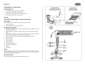
... speakers operate Speaker harness not (display lights normally) connected Not all other Blows fuses Power wire shorting to ground Speaker wires shorting to ground Incorrect fuse/fuse too small Corrective Action Check connection with the sale of this Warranty, the product is to be repaired or replaced with new or reconditioned product (at the address shown below reference. (Reference: 1 watt, 4-ohms) Frequency Response . . . . . 20Hz to 20kHz (-3dB), Auxiliary input used as source...
... speakers operate Speaker harness not (display lights normally) connected Not all other Blows fuses Power wire shorting to ground Speaker wires shorting to ground Incorrect fuse/fuse too small Corrective Action Check connection with the sale of this Warranty, the product is to be repaired or replaced with new or reconditioned product (at the address shown below reference. (Reference: 1 watt, 4-ohms) Frequency Response . . . . . 20Hz to 20kHz (-3dB), Auxiliary input used as source...

Owners Manual
Page 25
Audiovox Electronics Corporation 150 Marcus Boulevard Hauppauge, NY 11788 1-800-323-4815 www.jensen.com © 2005 Audiovox v.122304
Audiovox Electronics Corporation 150 Marcus Boulevard Hauppauge, NY 11788 1-800-323-4815 www.jensen.com © 2005 Audiovox v.122304
Quick Start Guide
Page 1
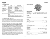
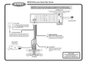
... 11 AUXILIARY INPUT CD CHANGER CONNECTOR CHASSIS GROUND Connect the black wire to the factory ground wire. MP5610 Receiver Quick Start Guide BATTERY Connect the yellow wire to the battery or 12 volt power source that is not provided, locate a clean, unpainted metal part of vehicle you have the installation handled by an experienced technician. If a factory ground wire is always live. ACCESSORY Connect the red wire to work. Connect the blue wire to a motorized antenna or to an optional amplifier. Need help...
... 11 AUXILIARY INPUT CD CHANGER CONNECTOR CHASSIS GROUND Connect the black wire to the factory ground wire. MP5610 Receiver Quick Start Guide BATTERY Connect the yellow wire to the battery or 12 volt power source that is not provided, locate a clean, unpainted metal part of vehicle you have the installation handled by an experienced technician. If a factory ground wire is always live. ACCESSORY Connect the red wire to work. Connect the blue wire to a motorized antenna or to an optional amplifier. Need help...

