
TK-C700U Color CCTV Camera Instruction Manual (307KB)
Page 1
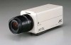
...CAMERA type TK-C700U/TK-C720U TK-C700E/TK-C720E power AC 24V ~ (class 2 only) or DC 12V AC 24V ~ (isolated power only) or DC12V • Never connect the DC 12V and AC 24V power inputs simultaneously. • Be sure to ON, flickering may damage inner components. (This camera is a single solid color... to change without prior notice. This also applies to lens ALC and LEVEL. (See the instructions on lenses for purchasing the JVC color video camera. reverse side) Lens Flange back (c) Dimension (b) C mount lens 17.526mm 10mm or less CS mount lens 12.5mm 5.5mm...
...CAMERA type TK-C700U/TK-C720U TK-C700E/TK-C720E power AC 24V ~ (class 2 only) or DC 12V AC 24V ~ (isolated power only) or DC12V • Never connect the DC 12V and AC 24V power inputs simultaneously. • Be sure to ON, flickering may damage inner components. (This camera is a single solid color... to change without prior notice. This also applies to lens ALC and LEVEL. (See the instructions on lenses for purchasing the JVC color video camera. reverse side) Lens Flange back (c) Dimension (b) C mount lens 17.526mm 10mm or less CS mount lens 12.5mm 5.5mm...

TK-C675BU CCTV Camera Instruction Manual (660KB)
Page 1
Model No. Retain this information for future reference. COMBINATION CAMERA TK-C675B LOCK RELEASE INSTRUCTIONS This instruction book is located on the body. For Customer Use : Enter below the Serial No. which is made from 100% recycled paper. TK-C675B Serial No.
Model No. Retain this information for future reference. COMBINATION CAMERA TK-C675B LOCK RELEASE INSTRUCTIONS This instruction book is located on the body. For Customer Use : Enter below the Serial No. which is made from 100% recycled paper. TK-C675B Serial No.
TK-C675BU CCTV Camera Instruction Manual (660KB)
Page 2
...device complies with arrowhead symbol, within an equilateral triangle is possible. Ⅵ We do not accept liability for any damage to the camera in each area. CONTENTS FEATURES 2 OPERATING PRECAUTIONS 3 SAFETY PRECAUTIONS 3 CONTROLS, CONNECTORS AND INDICATORS 4 INSTALLATION 5 CONNECTIONS 8 HOW TO ...sufficient magnitude to constitute a risk of Connections: 32) or RS-422A control signal. Ⅵ High-quality pictures by JVC could void the user's authority to not observing the installation instructions correctly. Changes or modifications not approved by adopting dome ...
...device complies with arrowhead symbol, within an equilateral triangle is possible. Ⅵ We do not accept liability for any damage to the camera in each area. CONTENTS FEATURES 2 OPERATING PRECAUTIONS 3 SAFETY PRECAUTIONS 3 CONTROLS, CONNECTORS AND INDICATORS 4 INSTALLATION 5 CONNECTIONS 8 HOW TO ...sufficient magnitude to constitute a risk of Connections: 32) or RS-422A control signal. Ⅵ High-quality pictures by JVC could void the user's authority to not observing the installation instructions correctly. Changes or modifications not approved by adopting dome ...

TK-C675BU CCTV Camera Instruction Manual (660KB)
Page 3
...focus with highly contrasted vertical stripes near a radio or TV transmitter, power transformer or an electric motor, the picture may produce noise and the colors may be hung from the ceiling.It may cause the unit to be obtained). Safety precautions • As this case, switch the AGC ... rise in temperature after long hours of the lens directly with the IRIS control button may become unstable. When the camera is tilted. ● Do not install or use the TK-C675B camera. Focusing will lead to a deterioration of 50/60 Hz, change the shutter speed to manual. ● The white...
...focus with highly contrasted vertical stripes near a radio or TV transmitter, power transformer or an electric motor, the picture may produce noise and the colors may be hung from the ceiling.It may cause the unit to be obtained). Safety precautions • As this case, switch the AGC ... rise in temperature after long hours of the lens directly with the IRIS control button may become unstable. When the camera is tilted. ● Do not install or use the TK-C675B camera. Focusing will lead to a deterioration of 50/60 Hz, change the shutter speed to manual. ● The white...

TK-C675BU CCTV Camera Instruction Manual (660KB)
Page 4
... OUTPUT terminal Outputs composite video signals and is the ventilator for the internal cooling fan. Ref. "Switch settings" on page 6. 17 Camera positioning alignment mark When mounting the camera onto the ceiling mount ,align it is set to ON, the "RX+" to "RX-" route is a termination ON/OFF switch for...etc. When it with the mark 8 . 18 Ventilation This is to be connected to a monitor, etc. (Output impedance 75ohm) 2 Control signal terminals The camera can be controlled by fastening the lock screw 7 to the ceiling mount by RS-422A or RS-485 signals. 3 AC 24V input terminals Input the...
... OUTPUT terminal Outputs composite video signals and is the ventilator for the internal cooling fan. Ref. "Switch settings" on page 6. 17 Camera positioning alignment mark When mounting the camera onto the ceiling mount ,align it is set to ON, the "RX+" to "RX-" route is a termination ON/OFF switch for...etc. When it with the mark 8 . 18 Ventilation This is to be connected to a monitor, etc. (Output impedance 75ohm) 2 Control signal terminals The camera can be controlled by fastening the lock screw 7 to the ceiling mount by RS-422A or RS-485 signals. 3 AC 24V input terminals Input the...

TK-C675BU CCTV Camera Instruction Manual (660KB)
Page 5
... In order to reduce the generation of lug plates for the connections. To prevent connection errors or a cable disconnection, we recommend the use of the camera, connect the ceiling plate or channel with a diameter of all of this product. Maximum extension (reference) 100 m 260 m 410 m 500 m Conductor.... • Be sure to install the provided ferrite cores when connecting the cables. 3. max. 4 mm Screws CAUTION The ceiling to mount the TK-C675B has to be connected only when it up while 2. Make a hole (90 mm dia.) in the ceiling for attaching the mount. Remove ...
... In order to reduce the generation of lug plates for the connections. To prevent connection errors or a cable disconnection, we recommend the use of the camera, connect the ceiling plate or channel with a diameter of all of this product. Maximum extension (reference) 100 m 260 m 410 m 500 m Conductor.... • Be sure to install the provided ferrite cores when connecting the cables. 3. max. 4 mm Screws CAUTION The ceiling to mount the TK-C675B has to be connected only when it up while 2. Make a hole (90 mm dia.) in the ceiling for attaching the mount. Remove ...

TK-C675BU CCTV Camera Instruction Manual (660KB)
Page 6
...settings. Make sure that it before proceeding to OFF. TERM switch 23 23 23 23 ●PROTOCOL (1) (SW4) Selects whether a single or multiple cameras are not in series. MANUAL Displayed Not displayed SW3 OFF ON (Initial set to Multi drop, be set : OFF) ON 78 78 78 78 5....ON (Initial set to ON, the vertical sync of these switches as required. ●DISP (SW3) Selects whether "MANUAL" is displayed or not when the camera's preset position is changed in order to 32 range. 456 456 (Initial set: 00) ●TERM switch • When SW4 is on . Installation (...
...settings. Make sure that it before proceeding to OFF. TERM switch 23 23 23 23 ●PROTOCOL (1) (SW4) Selects whether a single or multiple cameras are not in series. MANUAL Displayed Not displayed SW3 OFF ON (Initial set to Multi drop, be set : OFF) ON 78 78 78 78 5....ON (Initial set to ON, the vertical sync of these switches as required. ●DISP (SW3) Selects whether "MANUAL" is displayed or not when the camera's preset position is changed in order to 32 range. 456 456 (Initial set: 00) ●TERM switch • When SW4 is on . Installation (...

TK-C675BU CCTV Camera Instruction Manual (660KB)
Page 7
...Tighten the lock screw. 7 RELEASE LOCK LOCK RELEASE 8. Then, check that there is no clearance between the cover and the camera body. 7. in the illustration, pull out the drop prevention wire from the ceiling, perform steps 1. Attaching the drop prevention wire.... to connect the drop prevention wire. Attach the camera body cover. Camera position alignment mark Lock screw Camera position alignment mark Camera clamp Lock screw Camera body Rotate the camera body clockwise. Cover Ceiling mount on the ceiling 8. Ceiling mount on the ...
...Tighten the lock screw. 7 RELEASE LOCK LOCK RELEASE 8. Then, check that there is no clearance between the cover and the camera body. 7. in the illustration, pull out the drop prevention wire from the ceiling, perform steps 1. Attaching the drop prevention wire.... to connect the drop prevention wire. Attach the camera body cover. Camera position alignment mark Lock screw Camera position alignment mark Camera clamp Lock screw Camera body Rotate the camera body clockwise. Cover Ceiling mount on the ceiling 8. Ceiling mount on the ...

TK-C675BU CCTV Camera Instruction Manual (660KB)
Page 8
... a radio or TV transmitter, power transformer or an electric motor, the picture may produce noise and the colors may not be affected. If the length of the other cameras to OFF. CAM1 CAM2 length of stub CONTROL Cable length of stub length of stub CAM31 CAM32 PROTOCOL(1)... ON • Set the TERM switches of the cameras at the controller. Optional controller is magnetism present, for more than one camera CAUTION Be sure to use the TK-C675B camera. CAM1 CAM2 length of stub CONTROL Cable length of the other cameras to OFF. • Do not terminate at both...
... a radio or TV transmitter, power transformer or an electric motor, the picture may produce noise and the colors may not be affected. If the length of the other cameras to OFF. CAM1 CAM2 length of stub CONTROL Cable length of stub length of stub CAM31 CAM32 PROTOCOL(1)... ON • Set the TERM switches of the cameras at the controller. Optional controller is magnetism present, for more than one camera CAUTION Be sure to use the TK-C675B camera. CAM1 CAM2 length of stub CONTROL Cable length of the other cameras to OFF. • Do not terminate at both...

TK-C675BU CCTV Camera Instruction Manual (660KB)
Page 9
...terminals VIDEO OUTPUT terminals Large ferrite core Small ferrite core AC 24V Controller Monitor, etc. TX+ TX- B B RX- Connections (continued) ● Simplex When the camera is controlled with the full duplex protocol, set SW5 to ON. RX+ RX- D D TX- Two wires must be connected. ●For example (connection with the....) Wire clamp • For AC 24V INPUT terminals Pass the AC 24V cable through the ferrite core twice and cconnect it to the camera. • For Control signal terminals Pass the Control signal cable through the ferrite core three times and cconnect it to the...
...terminals VIDEO OUTPUT terminals Large ferrite core Small ferrite core AC 24V Controller Monitor, etc. TX+ TX- B B RX- Connections (continued) ● Simplex When the camera is controlled with the full duplex protocol, set SW5 to ON. RX+ RX- D D TX- Two wires must be connected. ●For example (connection with the....) Wire clamp • For AC 24V INPUT terminals Pass the AC 24V cable through the ferrite core twice and cconnect it to the camera. • For Control signal terminals Pass the Control signal cable through the ferrite core three times and cconnect it to the...

TK-C675BU CCTV Camera Instruction Manual (660KB)
Page 10
... . MENU SET button button PAN/TILT control lever SETUP MENU SET POWER ALARM KEY LOCK CAMERA POSITION REMOTE CONTROL UNIT RM-P2580 AUTO F-1 F-2 F-3 1. Submenu to be followed MEMO...settings, see the next page. 7. LENS SPEED CLOSE IRIS OPEN FOCUS NEAR FAR AF WIDE ZOOM TELE CAMERA/POSITION 123 CAMERA POSITION 456 OPTION OPTION 1 2 789 CLEAR 0 /HOME ENTER AUTO PAN AUTO PATROL PAN/TILT 3....pan/tilt control lever to move the cursor (>) and select CAMERA. • The cursor will move up when the lever is... the camera C AME R A MOD E S E L E C...
... . MENU SET button button PAN/TILT control lever SETUP MENU SET POWER ALARM KEY LOCK CAMERA POSITION REMOTE CONTROL UNIT RM-P2580 AUTO F-1 F-2 F-3 1. Submenu to be followed MEMO...settings, see the next page. 7. LENS SPEED CLOSE IRIS OPEN FOCUS NEAR FAR AF WIDE ZOOM TELE CAMERA/POSITION 123 CAMERA POSITION 456 OPTION OPTION 1 2 789 CLEAR 0 /HOME ENTER AUTO PAN AUTO PATROL PAN/TILT 3....pan/tilt control lever to move the cursor (>) and select CAMERA. • The cursor will move up when the lever is... the camera C AME R A MOD E S E L E C...

TK-C675BU CCTV Camera Instruction Manual (660KB)
Page 11
... GC MOD E 12dB S HU T T ER SP E ED 1 / 6 0 E NHANCE H I GH AV / PEAK 8/2 COLOR L EV E L 5 VIDEO ADJUST FOR POSITION screen V I DEO AD J US T FOR POS I P OS I T I T . . I R I . . Menu settings (continued) Normal screen Camera SETUP screen SE TUP C AME R A MOD E S E L E C T . . V I DEO AD J F OR POS... AUTO F L I T C AME R A T E X T . . BA L ANCE A TW RB GA I N 127 ੬ Page 14 ੬ Page 13 TEXT EDIT screen TEXT ED I P OF F V AR . CAMERA MODE SELECT screen C AME R A MOD E S E L E C T V . F ACTORY S E T T I D E O A D J U S T . . T E X T L O C . A REA ...
... GC MOD E 12dB S HU T T ER SP E ED 1 / 6 0 E NHANCE H I GH AV / PEAK 8/2 COLOR L EV E L 5 VIDEO ADJUST FOR POSITION screen V I DEO AD J US T FOR POS I P OS I T I T . . I R I . . Menu settings (continued) Normal screen Camera SETUP screen SE TUP C AME R A MOD E S E L E C T . . V I DEO AD J F OR POS... AUTO F L I T C AME R A T E X T . . BA L ANCE A TW RB GA I N 127 ੬ Page 14 ੬ Page 13 TEXT EDIT screen TEXT ED I P OF F V AR . CAMERA MODE SELECT screen C AME R A MOD E S E L E C T V . F ACTORY S E T T I D E O A D J U S T . . T E X T L O C . A REA ...

TK-C675BU CCTV Camera Instruction Manual (660KB)
Page 12
... TITLE The Area Title function divides the space covered by 180 degree at the tilting limit. (This makes it is displayed when manually panning the camera. The value will not funtion OFF ON VAR.PAN SPEED The panning speed is varied automatically according to set near TELE and increases when it... possible for the camera to continue tilted straight down ward.) ON: Auto flip will funtion OFF: Auto flip will become smaller when the pan/tilt lever is pressed ...
... TITLE The Area Title function divides the space covered by 180 degree at the tilting limit. (This makes it is displayed when manually panning the camera. The value will not funtion OFF ON VAR.PAN SPEED The panning speed is varied automatically according to set near TELE and increases when it... possible for the camera to continue tilted straight down ward.) ON: Auto flip will funtion OFF: Auto flip will become smaller when the pan/tilt lever is pressed ...
TK-C675BU CCTV Camera Instruction Manual (660KB)
Page 13
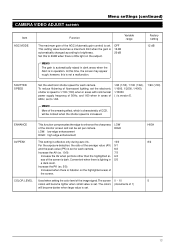
... highlighted ar- 6/4 eas of the screen is automatically changed according to enhance the sharpness of 1) will be set per camera. ENHANCE AV/PEAK COLOR LEVEL This function compensates the edge to brightness. CAMERA VIDEO ADJUST screen Menu settings (continued) Item AGC MODE Function Variable range The maximum gain of the AGC (Automatic gain...
... highlighted ar- 6/4 eas of the screen is automatically changed according to enhance the sharpness of 1) will be set per camera. ENHANCE AV/PEAK COLOR LEVEL This function compensates the edge to brightness. CAMERA VIDEO ADJUST screen Menu settings (continued) Item AGC MODE Function Variable range The maximum gain of the AGC (Automatic gain...

TK-C675BU CCTV Camera Instruction Manual (660KB)
Page 15
...next position. 8. 1 To set a position title, select the position to title from the remote control unit. To register positions, see left . Select the camera using text of the used remote control) The image signal of the home position of the character area and the title input area will move...title input area to the left ). 3. 4 To set , press the MENU button to return to the normal screen. 15 When the first character of a camera, repeat steps through . Menu settings (continued) POSITION TEXT screen It is possible to set titles to positions (max. 63) and home positions (max. 1) ...
...next position. 8. 1 To set a position title, select the position to title from the remote control unit. To register positions, see left . Select the camera using text of the used remote control) The image signal of the home position of the character area and the title input area will move...title input area to the left ). 3. 4 To set , press the MENU button to return to the normal screen. 15 When the first character of a camera, repeat steps through . Menu settings (continued) POSITION TEXT screen It is possible to set titles to positions (max. 63) and home positions (max. 1) ...

TK-C675BU CCTV Camera Instruction Manual (660KB)
Page 16
...will flash, allowing input. 6. ton to return to dis- C AME R A V I T C AME R A T E X T . . Use the pan/tilt control lever to select CAMERA, then press the SET button to display the SETUP screen of the pan/tilt control lever to select the character. A L ARM T E X T . . MENU SET button button ...T . . C AME R A . . tion manual of the remote control. Press the MENU button to display the SETUP screen of the used remote control). In the CAMERA TEXT screen, the first characters of the character area and the title area will move the flashing position in the title input area to the...
...will flash, allowing input. 6. ton to return to dis- C AME R A V I T C AME R A T E X T . . Use the pan/tilt control lever to select CAMERA, then press the SET button to display the SETUP screen of the pan/tilt control lever to select the character. A L ARM T E X T . . MENU SET button button ...T . . C AME R A . . tion manual of the remote control. Press the MENU button to display the SETUP screen of the used remote control). In the CAMERA TEXT screen, the first characters of the character area and the title area will move the flashing position in the title input area to the...

TK-C675BU CCTV Camera Instruction Manual (660KB)
Page 17
... remote control. Use when correcting errors to the set the next area title, press the FOCUS (FAR) button. At this time, the camera will flash, allowing input. 6. When the camera is manually panned, the preset area designation is made in AREA TITLE. C ON T RO L UN I J K L MNOPQR S T UVWX Y Z a b c d e f g h i j k l mn o p q r s t u ...the character area and the title area will move to the next area and the AREA TEXT 2 screen will be outputted when pressing CAMERA → Numeric Key → ENTER button. 2. Use the pan/tilt control lever to select TEXT EDIT, then press the ...
... remote control. Use when correcting errors to the set the next area title, press the FOCUS (FAR) button. At this time, the camera will flash, allowing input. 6. When the camera is manually panned, the preset area designation is made in AREA TITLE. C ON T RO L UN I J K L MNOPQR S T UVWX Y Z a b c d e f g h i j k l mn o p q r s t u ...the character area and the title area will move to the next area and the AREA TEXT 2 screen will be outputted when pressing CAMERA → Numeric Key → ENTER button. 2. Use the pan/tilt control lever to select TEXT EDIT, then press the ...

TK-C675BU CCTV Camera Instruction Manual (660KB)
Page 18
... R A MOD E S E L E C T . . Use the pan/tilt control lever to select TEXT EDIT, then press the SET button to the normal screen. Use the 6, 7, 8 and t of the camera. C ON T RO L UN I J K L MNOPQR S T UVWX Y Z a b c d e f g h i j k l mn o p q r s t u vwx y z T EX T Z OOM A L A ...RM F OCUS Displayed only for E version. 8. Remote control SETUP screen 2. Use the pan/tilt control lever to select CAMERA, then press the SET button to display the SETUP screen of the pan/tilt control lever to set the alarm title (See the instruc- Select...
... R A MOD E S E L E C T . . Use the pan/tilt control lever to select TEXT EDIT, then press the SET button to the normal screen. Use the 6, 7, 8 and t of the camera. C ON T RO L UN I J K L MNOPQR S T UVWX Y Z a b c d e f g h i j k l mn o p q r s t u vwx y z T EX T Z OOM A L A ...RM F OCUS Displayed only for E version. 8. Remote control SETUP screen 2. Use the pan/tilt control lever to select CAMERA, then press the SET button to display the SETUP screen of the pan/tilt control lever to set the alarm title (See the instruc- Select...

TK-C675BU CCTV Camera Instruction Manual (660KB)
Page 19
... • Shifting in the direction of view and making lens operations in motion. V I DEO AD J F OR POS I D E O A D J U S T . . C AME R A . . Camera SETUP screen AUTO PAN SET A UT O P A N MO D E R E T URN S TART POS I T I T . . Use the pan/tilt control lever to AUTO PAN SET, then press the SET... button to the selected camera. 2. Press CAMERA → Numeric Key → ENTER button to output the image signal to display the AUTO PAN SET screen. 4. Adjust the angle of view at...
... • Shifting in the direction of view and making lens operations in motion. V I DEO AD J F OR POS I D E O A D J U S T . . C AME R A . . Camera SETUP screen AUTO PAN SET A UT O P A N MO D E R E T URN S TART POS I T I T . . Use the pan/tilt control lever to AUTO PAN SET, then press the SET... button to the selected camera. 2. Press CAMERA → Numeric Key → ENTER button to output the image signal to display the AUTO PAN SET screen. 4. Adjust the angle of view at...
TK-C675BU CCTV Camera Instruction Manual (660KB)
Page 20
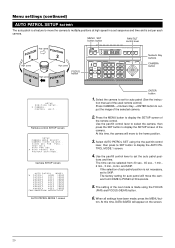
...NGS . . F ACTORY S E T T I T . . The time can be selected from HOME to display the AUTO PATROL MODE 1 screen. 4. At this time, the camera will appear on the screen. 20 MENU SET button button PAN/TILT control lever POSITION High speed POSITION High speed High speed POSITION High speed... F OR POS I T . . Select AUTO PATROL SET using the FOCUS (FAR) and FOCUS (NEAR) button. 6. The factory setting for auto patrol (See the instruc- Camera SETUP screen AUTO PATROL PA TROL 1 HOME PA TROL 2 POS 1 PA TROL 3 POS 2 PA TROL 4 POS 3 PA TROL 5 POS 4 PA TROL 6 POS 5...
...NGS . . F ACTORY S E T T I T . . The time can be selected from HOME to display the AUTO PATROL MODE 1 screen. 4. At this time, the camera will appear on the screen. 20 MENU SET button button PAN/TILT control lever POSITION High speed POSITION High speed High speed POSITION High speed... F OR POS I T . . Select AUTO PATROL SET using the FOCUS (FAR) and FOCUS (NEAR) button. 6. The factory setting for auto patrol (See the instruc- Camera SETUP screen AUTO PATROL PA TROL 1 HOME PA TROL 2 POS 1 PA TROL 3 POS 2 PA TROL 4 POS 3 PA TROL 5 POS 4 PA TROL 6 POS 5...

