
TK-C700U Color CCTV Camera Instruction Manual (307KB)
Page 1
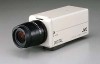
...como una cadena metálica o similar. Read all of the appliance and to normal operation. Use a damp cloth for purchasing the JVC color video camera. Do not use the 4-P plug supplied. The appliance may fall of any service or repairs to install it . 13. Slots and ...;ra vidéo couleur JVC. Ceci est typique des capteurs CCD et ne constitue pas une défaillance. • Si l'on the appliance. 14. Si l'objectif ne renferme pas d'amplificateur EE, tourner le commutateur sur le côté "DC". 5. Type de CAMERA TK-C700U/TK-C720U TK-C700E/TK-C720E Alimentation CA 24 V...
...como una cadena metálica o similar. Read all of the appliance and to normal operation. Use a damp cloth for purchasing the JVC color video camera. Do not use the 4-P plug supplied. The appliance may fall of any service or repairs to install it . 13. Slots and ...;ra vidéo couleur JVC. Ceci est typique des capteurs CCD et ne constitue pas une défaillance. • Si l'on the appliance. 14. Si l'objectif ne renferme pas d'amplificateur EE, tourner le commutateur sur le côté "DC". 5. Type de CAMERA TK-C700U/TK-C720U TK-C700E/TK-C720E Alimentation CA 24 V...

TK-C675BU CCTV Camera Instruction Manual (660KB)
Page 1
For Customer Use : Enter below the Serial No. COMBINATION CAMERA TK-C675B LOCK RELEASE INSTRUCTIONS This instruction book is located on the body. Model No. which is made from 100% recycled paper. Retain this information for future reference. TK-C675B Serial No.
For Customer Use : Enter below the Serial No. COMBINATION CAMERA TK-C675B LOCK RELEASE INSTRUCTIONS This instruction book is located on the body. Model No. which is made from 100% recycled paper. Retain this information for future reference. TK-C675B Serial No.
TK-C675BU CCTV Camera Instruction Manual (660KB)
Page 2
... when the zoom lens is set near WIDE.) Ⅵ Auto flip When the camera reaches its tilting limit, it automatically flips itself over by 180 degrees by JVC could void the user's authority to design modifications, data given in each area. ... control signal. Ⅵ High-quality pictures by adopting dome cover with optical distortion compensation and CCD with 16x zoom ratio (f=4.5 to the camera in the literature accompanying the appliance. CONTENTS FEATURES 2 OPERATING PRECAUTIONS 3 SAFETY PRECAUTIONS 3 CONTROLS, CONNECTORS AND INDICATORS 4 INSTALLATION 5 CONNECTIONS 8...
... when the zoom lens is set near WIDE.) Ⅵ Auto flip When the camera reaches its tilting limit, it automatically flips itself over by 180 degrees by JVC could void the user's authority to design modifications, data given in each area. ... control signal. Ⅵ High-quality pictures by adopting dome cover with optical distortion compensation and CCD with 16x zoom ratio (f=4.5 to the camera in the literature accompanying the appliance. CONTENTS FEATURES 2 OPERATING PRECAUTIONS 3 SAFETY PRECAUTIONS 3 CONTROLS, CONNECTORS AND INDICATORS 4 INSTALLATION 5 CONNECTIONS 8...

TK-C675BU CCTV Camera Instruction Manual (660KB)
Page 3
... or installer for more , the contact resistance of the horizontal rotary parts may increase after installation. ● When this camera is used in the AUTO white balance mode, the recorded colors may be slightly different from the ceiling.It may malfunction if it is placed on a surface or if it is... not be sure to install the provided ferrite cores when connecting the cables. (See "How to monitor the same position continuously for indoor use the TK-C675B camera. at least once a week (to initialize) and also clean the contacts. ● Do not touch the dome cover of the lens directly with...
... or installer for more , the contact resistance of the horizontal rotary parts may increase after installation. ● When this camera is used in the AUTO white balance mode, the recorded colors may be slightly different from the ceiling.It may malfunction if it is placed on a surface or if it is... not be sure to install the provided ferrite cores when connecting the cables. (See "How to monitor the same position continuously for indoor use the TK-C675B camera. at least once a week (to initialize) and also clean the contacts. ● Do not touch the dome cover of the lens directly with...

TK-C675BU CCTV Camera Instruction Manual (660KB)
Page 4
... route is terminated via 110Ω resistor. 12 Hook for attaching the drop prevention wire Attach the drop prevention wire 4 to fix the camera. 8 Camera position alignment mark Align with the mark 8 . 18 Ventilation This is the ventilator for the input signals to a monitor, etc. (Output ... Isolated power only (E type) Class 2 only (U type) 4 Drop prevention wire Engage this wire in the drop prevention wire hook 12 on the camera. 5 Mounting holes (× 4) Use these holes. 10 Terminal board cover Protects the cable connection terminals against dirt, etc. 11 Control signal termination ...
... route is terminated via 110Ω resistor. 12 Hook for attaching the drop prevention wire Attach the drop prevention wire 4 to fix the camera. 8 Camera position alignment mark Align with the mark 8 . 18 Ventilation This is the ventilator for the input signals to a monitor, etc. (Output ... Isolated power only (E type) Class 2 only (U type) 4 Drop prevention wire Engage this wire in the drop prevention wire hook 12 on the camera. 5 Mounting holes (× 4) Use these holes. 10 Terminal board cover Protects the cable connection terminals against dirt, etc. 11 Control signal termination ...

TK-C675BU CCTV Camera Instruction Manual (660KB)
Page 5
...come into contact with the ceiling mount using 4 screws, while pay- max. 4 mm Screws CAUTION The ceiling to mount the TK-C675B has to control the camera using wood screws, use of the coaxial cables as shown on the ceiling mount. 5 If the ceiling is required to be ... prevent accidental dropping of unnecessary signals, be sure to connect the AC 24 V cables correctly. CAUTION In order to reduce the generation of the camera, connect the ceiling plate or channel with the drop prevention wire. • Be sure to install the provided ferrite cores when connecting the cables....
...come into contact with the ceiling mount using 4 screws, while pay- max. 4 mm Screws CAUTION The ceiling to mount the TK-C675B has to control the camera using wood screws, use of the coaxial cables as shown on the ceiling mount. 5 If the ceiling is required to be ... prevent accidental dropping of unnecessary signals, be sure to connect the AC 24 V cables correctly. CAUTION In order to reduce the generation of the camera, connect the ceiling plate or channel with the drop prevention wire. • Be sure to install the provided ferrite cores when connecting the cables....

TK-C675BU CCTV Camera Instruction Manual (660KB)
Page 6
... DISP SW4 PROTOCOL (1) SW5 PROTOCOL (2) SW6 SYNC DOUBLE SINGLE FIGURES FIGURES 901 901 456 456 123456 Machine ID CAUTION The setting of the camera is on page 9. ●SYNC (SW6) When this switch should be carried out properly, so that it is set to ON. "...Control signal connection" is locked to the communication protocol used for the present. Camera body cover Camera body cover Setting switches RELEASE RELEASE LOCK LOCK LOCK RELEASE Mark Transportation bracket 4. Transportation bracket is mounted when it is changed in...
... DISP SW4 PROTOCOL (1) SW5 PROTOCOL (2) SW6 SYNC DOUBLE SINGLE FIGURES FIGURES 901 901 456 456 123456 Machine ID CAUTION The setting of the camera is on page 9. ●SYNC (SW6) When this switch should be carried out properly, so that it is set to ON. "...Control signal connection" is locked to the communication protocol used for the present. Camera body cover Camera body cover Setting switches RELEASE RELEASE LOCK LOCK LOCK RELEASE Mark Transportation bracket 4. Transportation bracket is mounted when it is changed in...

TK-C675BU CCTV Camera Instruction Manual (660KB)
Page 7
... checked. to connect the drop prevention wire. CAUTION Be sure to tighten the lock screw fully. Otherwise the camera body may drop from the ceiling mount and engage it is loose. 2) Align the camera position alignment mark (^) on the ceiling mount with the drop prevention wire hook on the ceiling mount. 4) Tighten...
... checked. to connect the drop prevention wire. CAUTION Be sure to tighten the lock screw fully. Otherwise the camera body may drop from the ceiling mount and engage it is loose. 2) Align the camera position alignment mark (^) on the ceiling mount with the drop prevention wire hook on the ceiling mount. 4) Tighten...

TK-C675BU CCTV Camera Instruction Manual (660KB)
Page 8
... used where there are strong electromagnetic waves or where there is magnetism present, for more than one camera CAUTION Be sure to use the TK-C675B camera. Please contact your local dealer or installer for example near a radio or TV transmitter, power transformer or an electric motor, the ...picture may produce noise and the colors may not be made correctly. ● When the controller is composed of stub ...
... used where there are strong electromagnetic waves or where there is magnetism present, for more than one camera CAUTION Be sure to use the TK-C675B camera. Please contact your local dealer or installer for example near a radio or TV transmitter, power transformer or an electric motor, the ...picture may produce noise and the colors may not be made correctly. ● When the controller is composed of stub ...

TK-C675BU CCTV Camera Instruction Manual (660KB)
Page 9
..., etc. s control signal connection Use a twisted-pair cable for the connection. ● Duplex When the camera is controlled with the simplex transmission protocol, set SW5 to OFF. B B RX- Camera RX+ RX- Two wires must be sure to the camera. 9 How to use the ferrite core In order to reduce the generation of the... the right.) Wire clamp • For AC 24V INPUT terminals Pass the AC 24V cable through the ferrite core twice and cconnect it to the camera. • For Control signal terminals Pass the Control signal cable through the ferrite core three times and cconnect it to the...
..., etc. s control signal connection Use a twisted-pair cable for the connection. ● Duplex When the camera is controlled with the simplex transmission protocol, set SW5 to OFF. B B RX- Camera RX+ RX- Two wires must be sure to the camera. 9 How to use the ferrite core In order to reduce the generation of the... the right.) Wire clamp • For AC 24V INPUT terminals Pass the AC 24V cable through the ferrite core twice and cconnect it to the camera. • For Control signal terminals Pass the Control signal cable through the ferrite core three times and cconnect it to the...

TK-C675BU CCTV Camera Instruction Manual (660KB)
Page 10
... submenu settings, see the next page. 7. UP L AUTO F L I T L E OF F A LM . MENU SET button button PAN/TILT control lever SETUP MENU SET POWER ALARM KEY LOCK CAMERA POSITION REMOTE CONTROL UNIT RM-P2580 AUTO F-1 F-2 F-3 1. Press the SET button to ON. 2. SETUP screen (main menu) SE TUP C AME R A MOD E S E L E C T . . ... left (8). • The value will appear when changes have been made . Read it and refer also to the JVC's remote control unit RM-P2580. Menu settings This chapter shows an example of connection to the instruction manual of the RM-P2580.
... submenu settings, see the next page. 7. UP L AUTO F L I T L E OF F A LM . MENU SET button button PAN/TILT control lever SETUP MENU SET POWER ALARM KEY LOCK CAMERA POSITION REMOTE CONTROL UNIT RM-P2580 AUTO F-1 F-2 F-3 1. Press the SET button to ON. 2. SETUP screen (main menu) SE TUP C AME R A MOD E S E L E C T . . ... left (8). • The value will appear when changes have been made . Read it and refer also to the JVC's remote control unit RM-P2580. Menu settings This chapter shows an example of connection to the instruction manual of the RM-P2580.

TK-C675BU CCTV Camera Instruction Manual (660KB)
Page 11
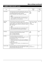
AUTO PATROL SE T . . PHASE 127 P OS . T E X T S I Z E NORMA L ੬ Page 12 CAMERA VIDEO ADJUST screen C AME R A V I D E O A D J U S T A GC MOD E 12dB S HU T T ER SP E ED 1 / 6 0 E NHANCE H I GH AV / PEAK 8/2 COLOR L EV E L 5 VIDEO ADJUST FOR POSITION screen V I DEO AD J US T FOR POS I P OS I T I . . V I DEO AD J F OR POS I ON T E X T . . U P-L AUTO F L I D E O A D J U S T . . C AME R A V I P OF F V AR . A REA T EX T . . AUTO PAN ...
AUTO PATROL SE T . . PHASE 127 P OS . T E X T S I Z E NORMA L ੬ Page 12 CAMERA VIDEO ADJUST screen C AME R A V I D E O A D J U S T A GC MOD E 12dB S HU T T ER SP E ED 1 / 6 0 E NHANCE H I GH AV / PEAK 8/2 COLOR L EV E L 5 VIDEO ADJUST FOR POSITION screen V I DEO AD J US T FOR POS I P OS I T I . . V I DEO AD J F OR POS I ON T E X T . . U P-L AUTO F L I D E O A D J U S T . . C AME R A V I P OF F V AR . A REA T EX T . . AUTO PAN ...

TK-C675BU CCTV Camera Instruction Manual (660KB)
Page 12
... left (8). UP: positions the title at the bottom of the screen. UP-L, DOWN-L UP-C, DOWN-C UP-R, COWN-R AUTO FLIP The camera is displayed when manually panning the camera. ON: Area title is displayed OFF: Area title is not displayed OFF ON Factory setting 127 UP-L OFF OFF OFF AREA 16... AREA 1 AREA 2 AREA 3 ALM.TEXT SIZE The character size to display during ALARM is set AREA TITLE is flipped over automatically by a camera into sixteen units, with a 16-character ID allocated to set near TELE and increases when it is set the display position of position titles. Adjust...
... left (8). UP: positions the title at the bottom of the screen. UP-L, DOWN-L UP-C, DOWN-C UP-R, COWN-R AUTO FLIP The camera is displayed when manually panning the camera. ON: Area title is displayed OFF: Area title is not displayed OFF ON Factory setting 127 UP-L OFF OFF OFF AREA 16... AREA 1 AREA 2 AREA 3 ALM.TEXT SIZE The character size to display during ALARM is set AREA TITLE is flipped over automatically by a camera into sixteen units, with a 16-character ID allocated to set near TELE and increases when it is set the display position of position titles. Adjust...
TK-C675BU CCTV Camera Instruction Manual (660KB)
Page 13
...only during auto iris. 10/0 For the exposure detection, the ratio of the average value (AV) 9/1 and the peak value (PK) is set for each camera. 8/2 Increase the AV (ex. 10/0): 7/3 Increase the AV when portions other than the highlighted ar- 6/4 eas of the screen is dark. HIGH 8/2.... Factory setting 12 dB SHUTTER SPEED Set the electronic shutter speed for each camera. Used when setting the color level of the image signal.The screen 0 ~ 10 colors will become lighter when small value is set . The colors (increments of 1) will become darker when large value is set . This ...
...only during auto iris. 10/0 For the exposure detection, the ratio of the average value (AV) 9/1 and the peak value (PK) is set for each camera. 8/2 Increase the AV (ex. 10/0): 7/3 Increase the AV when portions other than the highlighted ar- 6/4 eas of the screen is dark. HIGH 8/2.... Factory setting 12 dB SHUTTER SPEED Set the electronic shutter speed for each camera. Used when setting the color level of the image signal.The screen 0 ~ 10 colors will become lighter when small value is set . The colors (increments of 1) will become darker when large value is set . This ...

TK-C675BU CCTV Camera Instruction Manual (660KB)
Page 15
...not registered. In the POSITION TEXT screen, the first characters of the remote control, select CAMERA, then press the SET button to display the CAMERA SETUP screen. 2. Select the camera using text of a camera, repeat steps through . When all positions have been set a position title, select the ... the MENU button to return to the normal screen. 15 To register positions, see left . struction manual of the selected camera will move the flashing position in - The camera will be outputted. Use when correcting errors to the set title. 7. 3 6 To set titles to positions (max. ...
...not registered. In the POSITION TEXT screen, the first characters of the remote control, select CAMERA, then press the SET button to display the CAMERA SETUP screen. 2. Select the camera using text of a camera, repeat steps through . When all positions have been set a position title, select the ... the MENU button to return to the normal screen. 15 To register positions, see left . struction manual of the selected camera will move the flashing position in - The camera will be outputted. Use when correcting errors to the set title. 7. 3 6 To set titles to positions (max. ...

TK-C675BU CCTV Camera Instruction Manual (660KB)
Page 16
... g h i j k l mn o p q r s t u vwx y z S E L E C T T E X T Z OOM Displayed only for E version. 7. Press the MENU button to display the SETUP screen of the used remote control). At this time, the camera will move the flashing position in the title input area to the left. When the first character of the title as a title during... camera selection. Use when correcting errors to the set title. 1 7 s To set , press the MENU but- Pressing the ZOOM ...
... g h i j k l mn o p q r s t u vwx y z S E L E C T T E X T Z OOM Displayed only for E version. 7. Press the MENU button to display the SETUP screen of the used remote control). At this time, the camera will move the flashing position in the title input area to the left. When the first character of the title as a title during... camera selection. Use when correcting errors to the set title. 1 7 s To set , press the MENU but- Pressing the ZOOM ...

TK-C675BU CCTV Camera Instruction Manual (660KB)
Page 17
...SET button to display the AREA TEXT 1 screen. Select AREA TEXT, then press the SET button to display the SETUP screen of the camera. Pressing the ZOOM (WIDE) button will move on the screen. In the same manner as been selected, press the ZOOM (TELE) ...horizontal rotation) is divided into 16 sectors, allowing you to home position area 1. 5. It is possible to each area. C AME R A V I T C AME R A T E X T . . Camera SETUP screen TEXT ED I D E O A D J U S T . . This corresponds to check the title in AREA TITLE. Use when correcting errors to the set titles of the remote control.
...SET button to display the AREA TEXT 1 screen. Select AREA TEXT, then press the SET button to display the SETUP screen of the camera. Pressing the ZOOM (WIDE) button will move on the screen. In the same manner as been selected, press the ZOOM (TELE) ...horizontal rotation) is divided into 16 sectors, allowing you to home position area 1. 5. It is possible to each area. C AME R A V I T C AME R A T E X T . . Camera SETUP screen TEXT ED I D E O A D J U S T . . This corresponds to check the title in AREA TITLE. Use when correcting errors to the set titles of the remote control.

TK-C675BU CCTV Camera Instruction Manual (660KB)
Page 18
...→ ENTER button. Select ALARM TEXT, then press the SET button to display the TEXT EDIT screen. 4. C AME R A . . The image signal of the selected camera will move to the home position. SE TUP C AME R A MOD E S E L E C T . . V I DEO AD J F OR POS I NGS... FGH I T . . C AME R A V I T C AME R A T E X T . . tion manual of the pan/tilt control lever to select the character. Remote control SETUP screen 2. Camera SETUP screen 6. AUTO PAN SE T . . Menu settings (continued) ALARM TEXT screen It is possible to set the title. 9. TEXT ED I D E O A D J U S T . .
...→ ENTER button. Select ALARM TEXT, then press the SET button to display the TEXT EDIT screen. 4. C AME R A . . The image signal of the selected camera will move to the home position. SE TUP C AME R A MOD E S E L E C T . . V I DEO AD J F OR POS I NGS... FGH I T . . C AME R A V I T C AME R A T E X T . . tion manual of the pan/tilt control lever to select the character. Remote control SETUP screen 2. Camera SETUP screen 6. AUTO PAN SE T . . Menu settings (continued) ALARM TEXT screen It is possible to set the title. 9. TEXT ED I D E O A D J U S T . .

TK-C675BU CCTV Camera Instruction Manual (660KB)
Page 19
... appear and the stop position. Psitcatrut rpeoastittihoen Slow speed Psitcotpurpeoastittihoen MENU SET button button PAN/TILT control lever SETUP MENU SET POWER ALARM KEY LOCK CAMERA POSITION REMOTE CONTROL UNIT RM-P2580 AUTO F-1 F-2 F-3 Example: Action of view at the start position using the pan/tilt control lever. 5. C AME R A V I T . . T EXT ED I... of the used remote control). In the AUTO PAN SET screen, select AUTO PAN MODE. At this time, the camera will appear on the screen. s When selecting the mode to the normal screen. 19 Always check to make field...
... appear and the stop position. Psitcatrut rpeoastittihoen Slow speed Psitcotpurpeoastittihoen MENU SET button button PAN/TILT control lever SETUP MENU SET POWER ALARM KEY LOCK CAMERA POSITION REMOTE CONTROL UNIT RM-P2580 AUTO F-1 F-2 F-3 Example: Action of view at the start position using the pan/tilt control lever. 5. C AME R A V I T . . T EXT ED I... of the used remote control). In the AUTO PAN SET screen, select AUTO PAN MODE. At this time, the camera will appear on the screen. s When selecting the mode to the normal screen. 19 Always check to make field...
TK-C675BU CCTV Camera Instruction Manual (660KB)
Page 20
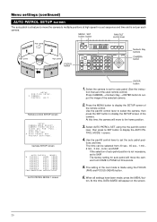
... display the AUTO PATROL MODE 1 screen. 4. Press the MENU button to display the SETUP screen of the next mode is not necessary, set per each camera. and SKIP. V I DEO AD J F OR POS I T . . tions and time. Remote control SETUP screen SE TUP C AME R A MOD E S E L E C T . . T EXT ED ... 1 3 0SEC 3 0SEC 3 0SEC 3 0SEC 3 0SEC 3 0SEC 3 0SEC 3 0SEC FOCUS AUTO PATROL MODE 1 screen ENTER button 1. At this time, the camera will move the camera from 30 sec., 45 sec., 1 min., 2 min., 3 min., 6 min. Menu settings (continued) AUTO PATROL SETUP screen The auto patrol is a feature to...
... display the AUTO PATROL MODE 1 screen. 4. Press the MENU button to display the SETUP screen of the next mode is not necessary, set per each camera. and SKIP. V I DEO AD J F OR POS I T . . tions and time. Remote control SETUP screen SE TUP C AME R A MOD E S E L E C T . . T EXT ED ... 1 3 0SEC 3 0SEC 3 0SEC 3 0SEC 3 0SEC 3 0SEC 3 0SEC 3 0SEC FOCUS AUTO PATROL MODE 1 screen ENTER button 1. At this time, the camera will move the camera from 30 sec., 45 sec., 1 min., 2 min., 3 min., 6 min. Menu settings (continued) AUTO PATROL SETUP screen The auto patrol is a feature to...

