
Instructions
Page 2
... remote controlled. Attention-Touche STANDBY/ON! L'alimentation ne peut pas être commandée à distance. "APPAREILS NUMERIQUES", NMB-003 EDICTEE PAR LE MINISTRE DES COMMUNICATIONS. These limits are designed to comply with Part 15 of the FCC Rules. If this appliance to the point of Conformity: Trade Name: JVC Model Number: RX-D205S/RX-D206B Responsible Party: JVC Americas Corp. Connect...
... remote controlled. Attention-Touche STANDBY/ON! L'alimentation ne peut pas être commandée à distance. "APPAREILS NUMERIQUES", NMB-003 EDICTEE PAR LE MINISTRE DES COMMUNICATIONS. These limits are designed to comply with Part 15 of the FCC Rules. If this appliance to the point of Conformity: Trade Name: JVC Model Number: RX-D205S/RX-D206B Responsible Party: JVC Americas Corp. Connect...

Instructions
Page 3
... started 4 Before Installation 4 Checking the supplied accessories 4 Putting batteries in the remote control 4 Connecting the FM and AM antennas 5 Connecting the speakers 6 Connecting video components 7 USB connection 10 Connecting the power cord 11 Basic operations 12 1 Turn on the power 12 2 Select the source to play 12 3 Adjust the volume 13 Turning off the sounds temporarily 14 Changing the display brightness 14 Turning off the power with the Sleep Timer 14 Basic settings 15 Setting the speaker information easily -Quick Speaker Setup 15 Basic setting items 16 Operating...
... started 4 Before Installation 4 Checking the supplied accessories 4 Putting batteries in the remote control 4 Connecting the FM and AM antennas 5 Connecting the speakers 6 Connecting video components 7 USB connection 10 Connecting the power cord 11 Basic operations 12 1 Turn on the power 12 2 Select the source to play 12 3 Adjust the volume 13 Turning off the sounds temporarily 14 Changing the display brightness 14 Turning off the power with the Sleep Timer 14 Basic settings 15 Setting the speaker information easily -Quick Speaker Setup 15 Basic setting items 16 Operating...
Instructions
Page 4
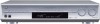
... 100 SURROUND 3 SOUND q 4 ENTER *LEVEL EX/ES/PL x 5 MENU w TUNING/REW FF/TUNING DIMMER 6 e REC PAUSE MEMORY FM MODE SLEEP r DVR/DVD VCR DBS MIDNIGHT 7 t ANALOG/ TV USB FM/AM DIGITAL y 8 TV/VIDEO u 9 TV VOLUME CHANNEL MUTING i VOLUME o REMOTE CONTROL RM-SRXD201J Remote control See pages in parentheses for details. 1 DVR/DVD mode selector (35, 38) 2 • Numeric buttons (26, 34 - 38) 1 - 10, 0, +10, 100+ • Adjusting buttons for operating a DVD recorder (JVC product ONLY) or DVD player...
... 100 SURROUND 3 SOUND q 4 ENTER *LEVEL EX/ES/PL x 5 MENU w TUNING/REW FF/TUNING DIMMER 6 e REC PAUSE MEMORY FM MODE SLEEP r DVR/DVD VCR DBS MIDNIGHT 7 t ANALOG/ TV USB FM/AM DIGITAL y 8 TV/VIDEO u 9 TV VOLUME CHANNEL MUTING i VOLUME o REMOTE CONTROL RM-SRXD201J Remote control See pages in parentheses for details. 1 DVR/DVD mode selector (35, 38) 2 • Numeric buttons (26, 34 - 38) 1 - 10, 0, +10, 100+ • Adjusting buttons for operating a DVD recorder (JVC product ONLY) or DVD player...

Instructions
Page 5
...) IN(PLAY) OUT IN IN OUT 5 6 7 SUBWOOFER OUT 8 4 ANTENNA AM LOOP SURROUND BACK SURROUND SPEAKERS SPEAKERS RIGHT LEFT RIGHT LEFT FM 75 COAXIAL CENTER SPEAKER AM EXT FRONT SPEAKERS RIGHT LEFT CAUTION:SPEAKER IMPEDANCE 6 -16 9 1 Power cord (11) 2 AV COMPU LINK-III terminals (32) 3 DIGITAL IN terminals (10) • Coaxial: 1(DVR/DVD) • Optical: 2(DBS) • Optical: 3(VCR) 4 ANTENNA terminals (5) 5 VIDEO jacks (7- 9) VIDEO (composite video) jacks, S-VIDEO jacks • Input: DBS IN, VCR IN (PLAY), DVR/DVD IN (PLAY) • Output: VCR...
...) IN(PLAY) OUT IN IN OUT 5 6 7 SUBWOOFER OUT 8 4 ANTENNA AM LOOP SURROUND BACK SURROUND SPEAKERS SPEAKERS RIGHT LEFT RIGHT LEFT FM 75 COAXIAL CENTER SPEAKER AM EXT FRONT SPEAKERS RIGHT LEFT CAUTION:SPEAKER IMPEDANCE 6 -16 9 1 Power cord (11) 2 AV COMPU LINK-III terminals (32) 3 DIGITAL IN terminals (10) • Coaxial: 1(DVR/DVD) • Optical: 2(DBS) • Optical: 3(VCR) 4 ANTENNA terminals (5) 5 VIDEO jacks (7- 9) VIDEO (composite video) jacks, S-VIDEO jacks • Input: DBS IN, VCR IN (PLAY), DVR/DVD IN (PLAY) • Output: VCR...

Instructions
Page 8
... rear panel, using a single speaker for the surround back speaker You can place a subwoofer wherever you like since bass sound is non-directional. Normally place it to 19. Connecting the speakers Turn off all components before making connections. 1 2 13 2 + + - - 1 Twist and remove the insulation at the end of a powered subwoofer to the SUBWOOFER OUT jack on the rear panel to obtain the best possible surround effect. After connecting all connections are completed. Connecting the speakers Do not connect the AC power plug...
... rear panel, using a single speaker for the surround back speaker You can place a subwoofer wherever you like since bass sound is non-directional. Normally place it to 19. Connecting the speakers Turn off all components before making connections. 1 2 13 2 + + - - 1 Twist and remove the insulation at the end of a powered subwoofer to the SUBWOOFER OUT jack on the rear panel to obtain the best possible surround effect. After connecting all connections are completed. Connecting the speakers Do not connect the AC power plug...

Instructions
Page 9
...) jacks, connect them using a digital coaxial or optical cable. If your video components have AV COMPU LINK terminal See also page 32 for details. • When using these input jacks are completed. Turn off all connections are transmitted only through this receiver may be distorted. See page 20 for detailed information about the connection and the AV COMPU LINK remote control system. 7 Connecting a DVD recorder or DVD player DVR DVR/DVD OUT(REC) IN(PLAY) COMPONENT VIDEO Y PB...
...) jacks, connect them using a digital coaxial or optical cable. If your video components have AV COMPU LINK terminal See also page 32 for details. • When using these input jacks are completed. Turn off all connections are transmitted only through this receiver may be distorted. See page 20 for detailed information about the connection and the AV COMPU LINK remote control system. 7 Connecting a DVD recorder or DVD player DVR DVR/DVD OUT(REC) IN(PLAY) COMPONENT VIDEO Y PB...

Instructions
Page 10
... COMPU LINK remote control system cannot operate properly. For details, see page 10. Å To component video output • Connect Y, PB, and PR correctly. ı To left/right audio channel output Ç To left/right audio channel input Î To composite video output ‰ To S-video output Ï To S-video input Ì To composite video input 8 When shipped from the factory, the digital input terminal setting for details. • When using a digital coaxial or optical cable. Do not connect the AC power plug to...
... COMPU LINK remote control system cannot operate properly. For details, see page 10. Å To component video output • Connect Y, PB, and PR correctly. ı To left/right audio channel output Ç To left/right audio channel input Î To composite video output ‰ To S-video output Ï To S-video input Ì To composite video input 8 When shipped from the factory, the digital input terminal setting for details. • When using a digital coaxial or optical cable. Do not connect the AC power plug to...

Instructions
Page 11
... R White Red Stereo audio cable (not supplied) Å TV ı Ç Î S-video cable (not supplied) Composite video cable (not supplied) NOTES • When using a stereo audio cable as the illustration above , set the audio input mode to "ANALOG." See page 20 for a DBS tuner is set the audio input mode to "ANALOG." For details of digital connection, see page 10. Å To component video input • Connect Y, PB, and PR correctly. ı To left /right audio channel output ı To component video output • Connect Y, PB...
... R White Red Stereo audio cable (not supplied) Å TV ı Ç Î S-video cable (not supplied) Composite video cable (not supplied) NOTES • When using a stereo audio cable as the illustration above , set the audio input mode to "ANALOG." See page 20 for a DBS tuner is set the audio input mode to "ANALOG." For details of digital connection, see page 10. Å To component video input • Connect Y, PB, and PR correctly. ı To left /right audio channel output ı To component video output • Connect Y, PB...

Instructions
Page 12
... running . 2. Connect the unit to operate the connected component (except DBS tuner) using a digital optical cable (not supplied). PC USB cable (not supplied) • Use "USB series A plug to minimum. IMPORTANT: Always set for the first time, follow the procedure below. • Remember you want to the PC using a digital coaxial cable (not supplied). Turn on page 20. • Select the correct digital input mode. When the component has a digital coaxial output terminal, connect it to the 1(DVR/DVD) terminal, using a USB cable (not supplied). IMPORTANT...
... running . 2. Connect the unit to operate the connected component (except DBS tuner) using a digital optical cable (not supplied). PC USB cable (not supplied) • Use "USB series A plug to minimum. IMPORTANT: Always set for the first time, follow the procedure below. • Remember you want to the PC using a digital coaxial cable (not supplied). Turn on page 20. • Select the correct digital input mode. When the component has a digital coaxial output terminal, connect it to the 1(DVR/DVD) terminal, using a USB cable (not supplied). IMPORTANT...

Instructions
Page 13
... and the receiver while the receiver is set to [USB Audio DAC]. - If no sound comes from the connecting cables and the antenna. select "USB" as the playback source, disconnect the USB cable. If it does not work yet, restart Windows. • The installed drivers can use your PC settings and PC specifications. • Use a USB cable (version 1.1 or later). Connecting the power cord When all the audio/video connections have the power cord replaced with the USB device. - The standby lamp lights in the...
... and the receiver while the receiver is set to [USB Audio DAC]. - If no sound comes from the connecting cables and the antenna. select "USB" as the playback source, disconnect the USB cable. If it does not work yet, restart Windows. • The installed drivers can use your PC settings and PC specifications. • Use a USB cable (version 1.1 or later). Connecting the power cord When all the audio/video connections have the power cord replaced with the USB device. - The standby lamp lights in the...

Instructions
Page 14
... component. DBS*1: Select this for each source. USB: Select this for the DVD recorder or DVD player. From the remote control: Press one of the source selecting buttons. • For "FM" and "AM," press FM/AM. ANALOG AUTO SURR L R S.WFR TUNED STEREO AUTO MUTING MHz To turn the power off the power (into standby) Press STANDBY/ON (or STANDBY/ON remote control) again. Basic operations 1 23 Source lamps 2 Select the source to play On the front panel: Turn SOURCE...
... component. DBS*1: Select this for each source. USB: Select this for the DVD recorder or DVD player. From the remote control: Press one of the source selecting buttons. • For "FM" and "AM," press FM/AM. ANALOG AUTO SURR L R S.WFR TUNED STEREO AUTO MUTING MHz To turn the power off the power (into standby) Press STANDBY/ON (or STANDBY/ON remote control) again. Basic operations 1 23 Source lamps 2 Select the source to play On the front panel: Turn SOURCE...

Instructions
Page 15
... fixed to activate the HEADPHONE mode. NOTE The volume level can be adjusted within the range of sound energy can enjoy not only stereo software but also multi-channel software through the headphones-3D HEADPHONE mode. DOLBY DIGITAL*2: Select to "DIGITAL AUTO." The HEADPHONE indicator lights up on the remote control). The ANALOG indicator lights up on the display. DTS*2: ANALOG: Select to turn MASTER VOLUME control counterclockwise (or press VOLUME - The receiver...
... fixed to activate the HEADPHONE mode. NOTE The volume level can be adjusted within the range of sound energy can enjoy not only stereo software but also multi-channel software through the headphones-3D HEADPHONE mode. DOLBY DIGITAL*2: Select to "DIGITAL AUTO." The HEADPHONE indicator lights up on the remote control). The ANALOG indicator lights up on the display. DTS*2: ANALOG: Select to turn MASTER VOLUME control counterclockwise (or press VOLUME - The receiver...

Instructions
Page 16
... display. Basic adjustment of auto memory This receiver memorizes sound settings for each source: • Analog/digital input mode (see page 12) • Bass boost (see page 23) • Digital equalization pattern (see page 22) • Input attenuator mode (see page 23) • Midnight mode (see page 20) • Speaker output level (see page 22) • Surround/DSP mode selection (see page 17. • The other speaker indicators light up . Changing the display...
... display. Basic adjustment of auto memory This receiver memorizes sound settings for each source: • Analog/digital input mode (see page 12) • Bass boost (see page 23) • Digital equalization pattern (see page 22) • Input attenuator mode (see page 23) • Midnight mode (see page 20) • Speaker output level (see page 22) • Surround/DSP mode selection (see page 17. • The other speaker indicators light up . Changing the display...

Instructions
Page 17
... speaker channel number changes as follows. • To select your listening room. There is canceled before you finish, start , remember... As you start from Surround/DSP modes (see "Adjusting the speaker output levels" on page 16. On the front panel ONLY: 1 Press SETTING and turn the jog, the room size changes as follows. • For the details of the setting process. • Once Quick Speaker Setup is now completed, then the display...
... speaker channel number changes as follows. • To select your listening room. There is canceled before you finish, start , remember... As you start from Surround/DSP modes (see "Adjusting the speaker output levels" on page 16. On the front panel ONLY: 1 Press SETTING and turn the jog, the room size changes as follows. • For the details of the setting process. • Once Quick Speaker Setup is now completed, then the display...

Instructions
Page 19
... SETTING. Setting the speakers To obtain the best possible surround effect from step 1 again. The subwoofer indicator ( S.WFR ) lights up on the display. 17 No sound comes from the surround back speaker if you connect it to the beginning) SUBWOOFER CENTER SPK S BACK SPK DIST UNIT FRONT R DIST SURR L DIST S BACK DIST S BACK R DIST DUAL MONO CROSSOVER MIDNIGHT MODE DIGITAL IN 2 DVD VIDEO IN DBS VIDEO IN 3 Press SET. Setting subwoofer information-SUBWOOFER...
... SETTING. Setting the speakers To obtain the best possible surround effect from step 1 again. The subwoofer indicator ( S.WFR ) lights up on the display. 17 No sound comes from the surround back speaker if you connect it to the beginning) SUBWOOFER CENTER SPK S BACK SPK DIST UNIT FRONT R DIST SURR L DIST S BACK DIST S BACK R DIST DUAL MONO CROSSOVER MIDNIGHT MODE DIGITAL IN 2 DVD VIDEO IN DBS VIDEO IN 3 Press SET. Setting subwoofer information-SUBWOOFER...

Instructions
Page 22
Using the Midnight mode -MIDNIGHT MODE You can enjoy a powerful sound at the same time. VCR For the VCR. Ex.: When "DIGITAL IN 1" is fixed to "S/C" and vice versa. 20 For the DVD recorder or DVD player (DVD VIDEO IN): DVD DVD Select when connecting the DVD recorder (or DVD player) to the composite video or S-video input jacks. Initial setting: DVD For the VCR (VCR VIDEO IN): VCR VCR Select when connecting the VCR to the composite...
Using the Midnight mode -MIDNIGHT MODE You can enjoy a powerful sound at the same time. VCR For the VCR. Ex.: When "DIGITAL IN 1" is fixed to "S/C" and vice versa. 20 For the DVD recorder or DVD player (DVD VIDEO IN): DVD DVD Select when connecting the DVD recorder (or DVD player) to the composite video or S-video input jacks. Initial setting: DVD For the VCR (VCR VIDEO IN): VCR VCR Select when connecting the VCR to the composite...

Instructions
Page 30
... (resulting in the speaker setting (see page 19). 28 When using a matrix encoding/decoding method, an additional "surround back" channel signal is detected, the and 96/24 indicators light up on the display. 3D HEADPHONE mode If you connect a pair of headphones while one of sound quality) and the surround signals transmitted through the digital input, the indicator lights up . When Dolby Pro Logic IIx...
... (resulting in the speaker setting (see page 19). 28 When using a matrix encoding/decoding method, an additional "surround back" channel signal is detected, the and 96/24 indicators light up on the display. 3D HEADPHONE mode If you connect a pair of headphones while one of sound quality) and the surround signals transmitted through the digital input, the indicator lights up . When Dolby Pro Logic IIx...
Instructions
Page 34
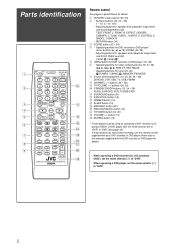
.... Composite video cable Composite video cable Monaural mini-plugs (not supplied) AV COMPU LINK-III Source equipment RX-D205S RX-D206B TV To video input 2 (Composite) Monaural mini-plugs (not supplied) AV COMPU LINK DVD player AV COMPU LINK Case 3: When connecting the source equipment to the receiver through the component video jacks, connect this receiver to the TV's video input 1 terminal using S-video cables. So you need to connect the video components you want to operate, following three ways. • When using the AV COMPU LINK remote control system, set the video input for...
.... Composite video cable Composite video cable Monaural mini-plugs (not supplied) AV COMPU LINK-III Source equipment RX-D205S RX-D206B TV To video input 2 (Composite) Monaural mini-plugs (not supplied) AV COMPU LINK DVD player AV COMPU LINK Case 3: When connecting the source equipment to the receiver through the component video jacks, connect this receiver to the TV's video input 1 terminal using S-video cables. So you need to connect the video components you want to operate, following three ways. • When using the AV COMPU LINK remote control system, set the video input for...

Instructions
Page 35
... this receiver using the audio cables. • See pages 7 to 9. 4 Connect the video input/output jacks on the VCR, DVD player, TV, and this receiver using the S-video cables, composite video cables, or component video cables. • See "Connections 2" on the previous page. 5 Plug the AC power cords of the TV, DVD player, and VCR using this remote control See pages 34 and 35 for the first time after the AV COMPU LINK connection, turn on automatically. • If the previously selected source is...
... this receiver using the audio cables. • See pages 7 to 9. 4 Connect the video input/output jacks on the VCR, DVD player, TV, and this receiver using the S-video cables, composite video cables, or component video cables. • See "Connections 2" on the previous page. 5 Plug the AC power cords of the TV, DVD player, and VCR using this remote control See pages 34 and 35 for the first time after the AV COMPU LINK connection, turn on automatically. • If the previously selected source is...
Instructions
Page 41
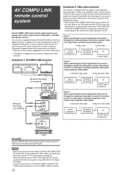
... is not plugged in. Set the mode selector to the incorrect position. Move the antenna farther from speakers. Consult your JVC's service center. Speaker signal cables are not connected properly. Select another station. Ignition noise from one speaker only. The receiver turns off . Sounds are weak. The power cord is not a malfunction. Turn on the receiver again, then turn it on the display, then the receiver turns off (enters standby mode). If speaker wiring is being used. Batteries are intermittently...
... is not plugged in. Set the mode selector to the incorrect position. Move the antenna farther from speakers. Consult your JVC's service center. Speaker signal cables are not connected properly. Select another station. Ignition noise from one speaker only. The receiver turns off . Sounds are weak. The power cord is not a malfunction. Turn on the receiver again, then turn it on the display, then the receiver turns off (enters standby mode). If speaker wiring is being used. Batteries are intermittently...


