Service Manual
Page 1
PC-XC350 SERVICE MANUAL CD PORTABLE COMPONEMT SYSTEM PC-XC350 Unit No. xxxxx OCT 2001 SP-PCXC350 Unit No. SP-PCXC350 contents Safety precaution 1-2 Disassembly method 1-4 Adjustment method 1-6 TOC read 1-11 Major IC Description 1-12 Unit No. SP-PCXC350 Area Suffix J-----USA C-----CANADA Block/Wiring Diagram 1-16 Circuit Diagram 1-18 PCB drawing 1-20 Assembly 1-22 Packing 1-32 COPYRIGHT © 2001 VICTOR COMPANY OF JAPAN,LTD (By JCA) No.
PC-XC350 SERVICE MANUAL CD PORTABLE COMPONEMT SYSTEM PC-XC350 Unit No. xxxxx OCT 2001 SP-PCXC350 Unit No. SP-PCXC350 contents Safety precaution 1-2 Disassembly method 1-4 Adjustment method 1-6 TOC read 1-11 Major IC Description 1-12 Unit No. SP-PCXC350 Area Suffix J-----USA C-----CANADA Block/Wiring Diagram 1-16 Circuit Diagram 1-18 PCB drawing 1-20 Assembly 1-22 Packing 1-32 COPYRIGHT © 2001 VICTOR COMPANY OF JAPAN,LTD (By JCA) No.
Service Manual
Page 2
... Service manual. Any leakage current must be identical to those used in the products are maintained. 3. Voltage measured Any must be confirmed that they have the same safety characteristics as the recommended replacement parts shown in the case of performing repair of the product should be made . Replacement parts must not exceed 0.5mA AC (r.m.s.) Alternate check method Plug the AC line cord directly...
... Service manual. Any leakage current must be identical to those used in the products are maintained. 3. Voltage measured Any must be confirmed that they have the same safety characteristics as the recommended replacement parts shown in the case of performing repair of the product should be made . Replacement parts must not exceed 0.5mA AC (r.m.s.) Alternate check method Plug the AC line cord directly...
Service Manual
Page 3
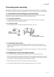
..., etc. For specific details, refer to adjust the semi-fixed resistor that adjusts the laser power. Handling the traverse unit (optical pickup) 1. It is discharged, can easily destory the laser diode. 1.2. is not possible to the replacement procdeure in devicessuch as a conductive sheet) or an iron plate over it before installation, both sides of the flexible cable using nippers, etc. Do...
..., etc. For specific details, refer to adjust the semi-fixed resistor that adjusts the laser power. Handling the traverse unit (optical pickup) 1. It is discharged, can easily destory the laser diode. 1.2. is not possible to the replacement procdeure in devicessuch as a conductive sheet) or an iron plate over it before installation, both sides of the flexible cable using nippers, etc. Do...
Service Manual
Page 4
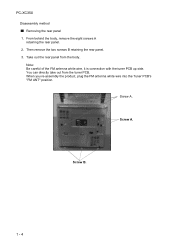
PC-XC350 Disaeesmbly method Removing the rear panel 1. You can directly take out from the body. When you re-assembly the product, plug the FM antenna white wire into the Tuner PCB's "FM ANT" position. Note: Be careful of the FM antenna white wire, it is connection with the tuner PCB up side. Take out the rear panel from the tuner PCB. Screw A. Screw B. 1 - 4 From behind the body, remove the eight screws A retaining the rear panel. 2. Screw A. Then remove the two screws B retaining the rear panel. 3.
PC-XC350 Disaeesmbly method Removing the rear panel 1. You can directly take out from the body. When you re-assembly the product, plug the FM antenna white wire into the Tuner PCB's "FM ANT" position. Note: Be careful of the FM antenna white wire, it is connection with the tuner PCB up side. Take out the rear panel from the tuner PCB. Screw A. Screw B. 1 - 4 From behind the body, remove the eight screws A retaining the rear panel. 2. Screw A. Then remove the two screws B retaining the rear panel. 3.
Service Manual
Page 5
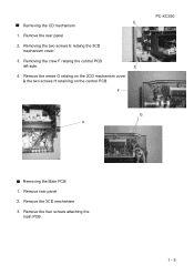
Remove the rear panel 2. Remove the srews G retaing on the 3CD mechanism cover & the two screws H retaining on the control PCB F PC-XC350 G H Removing the Main PCB 1. Remove the 3CD mechanism 3. Remove the four screws attaching the main PCB. 1 - 5 Remove rear panel 2. Removing the crew F retaing the control PCB left side. E 4. Removing the two screws E retaing the 3CD mechanism cover. 3. E Removing the CD mechanism 1.
Remove the rear panel 2. Remove the srews G retaing on the 3CD mechanism cover & the two screws H retaining on the control PCB F PC-XC350 G H Removing the Main PCB 1. Remove the 3CD mechanism 3. Remove the four screws attaching the main PCB. 1 - 5 Remove rear panel 2. Removing the crew F retaing the control PCB left side. E 4. Removing the two screws E retaing the 3CD mechanism cover. 3. E Removing the CD mechanism 1.
Service Manual
Page 6
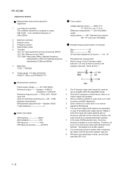
... play and tension FWD(CT-120m), and FF/REW(CT-F) Measurement conditions Power supply voltage----------AC 120V (60Hz) Reference output----------Speaker : 0.866V/3 Headphone : 0.245V/32 Reference frequency and -----1KHz, AUX : 450mV input level Input for measurement charateristics (125Hz and 8KHz) 1. Since a fixed coil is used, there is no need to perform and MIX adjustment. 5. The input and output earth systems are separated. PC-XC350 Adjustment method...
... play and tension FWD(CT-120m), and FF/REW(CT-F) Measurement conditions Power supply voltage----------AC 120V (60Hz) Reference output----------Speaker : 0.866V/3 Headphone : 0.245V/32 Reference frequency and -----1KHz, AUX : 450mV input level Input for measurement charateristics (125Hz and 8KHz) 1. Since a fixed coil is used, there is no need to perform and MIX adjustment. 5. The input and output earth systems are separated. PC-XC350 Adjustment method...
Service Manual
Page 7
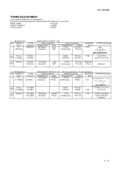
Supply voltage: DC 12.0V Speaker impedance: 3 OHMS Function switch: RADIO PC-XC350 a. FM Adjustment ste Adjusting Tuning circuit Frequency 1 IF (10.7 MHz) 98.0 MHz BAND SELECT SWITCH : FM FM Dummy Antenna : 75 ohm unbalance Input Connection Output Connection Adjustment Measurement input Measurement output parts FM Sweep TP4 (H) VTVM TP16 (H) Generator TP8 (E) Oscilloscope TP8(E) T104 VTVM Oscilloscope 2 Tuning 3 Coversage 4 Tracking 5 87.5 MHz 108 MHz 90.0 MHz 106.0 MHz -- Adjust the intermediate...
Supply voltage: DC 12.0V Speaker impedance: 3 OHMS Function switch: RADIO PC-XC350 a. FM Adjustment ste Adjusting Tuning circuit Frequency 1 IF (10.7 MHz) 98.0 MHz BAND SELECT SWITCH : FM FM Dummy Antenna : 75 ohm unbalance Input Connection Output Connection Adjustment Measurement input Measurement output parts FM Sweep TP4 (H) VTVM TP16 (H) Generator TP8 (E) Oscilloscope TP8(E) T104 VTVM Oscilloscope 2 Tuning 3 Coversage 4 Tracking 5 87.5 MHz 108 MHz 90.0 MHz 106.0 MHz -- Adjust the intermediate...
Service Manual
Page 9
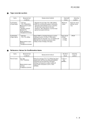
PC-XC350 Tape recorder section Items Confirmation of head angle Confirmation of tape speed Measurement conditions Measurement method Test tape : TCC-182A(8KHz) Measurement output terminal : Speaker terminal Speaker R/L (Load resistance: 3 : Headphone terminal 1 Playback the test tape TCC-182A (8KHz) 2 With the recording & playback mechanism, adjust the head azimuth screw so that the frequency counter reading becomes 3,010Hz +/-15Hz when playing back the test tape TCC-112 (3KHz...
PC-XC350 Tape recorder section Items Confirmation of head angle Confirmation of tape speed Measurement conditions Measurement method Test tape : TCC-182A(8KHz) Measurement output terminal : Speaker terminal Speaker R/L (Load resistance: 3 : Headphone terminal 1 Playback the test tape TCC-182A (8KHz) 2 With the recording & playback mechanism, adjust the head azimuth screw so that the frequency counter reading becomes 3,010Hz +/-15Hz when playing back the test tape TCC-112 (3KHz...

Service Manual
Page 10
... P.C. PC-XC350 Electrical Performance Items Measurement conditions Adjustment of recording blas current (Reference Value) Mode: Playback mode Recording mode Test tape TDK-D60 Measurement output terminal : Both recording and headphone terminals Adjustment of recording and palyback frequency characteristics Reference frequency :1KHz and 8KHz (REF.:-10dB) Test tape TDK-D60 Measurement input terminal : OSC IN Measurement method 1 With the recording and playback mechanism, load the test tapes TDK-D60, and set...
... P.C. PC-XC350 Electrical Performance Items Measurement conditions Adjustment of recording blas current (Reference Value) Mode: Playback mode Recording mode Test tape TDK-D60 Measurement output terminal : Both recording and headphone terminals Adjustment of recording and palyback frequency characteristics Reference frequency :1KHz and 8KHz (REF.:-10dB) Test tape TDK-D60 Measurement input terminal : OSC IN Measurement method 1 With the recording and playback mechanism, load the test tapes TDK-D60, and set...

