JVC PC-XC350 Support and Manuals
Get Help and Manuals for this JVC item
View All Support Options Below
Free JVC PC-XC350 manuals!
Problems with JVC PC-XC350?
Ask a Question
Free JVC PC-XC350 manuals!
Problems with JVC PC-XC350?
Ask a Question
Popular JVC PC-XC350 Manual Pages
Service Manual - Page 1
.../Wiring Diagram 1-16 Circuit Diagram 1-18 PCB drawing 1-20 Assembly 1-22 Packing 1-32
COPYRIGHT © 2001 VICTOR COMPANY OF JAPAN,LTD (By JCA)
No. PC-XC350
SERVICE MANUAL
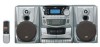
CD PORTABLE COMPONEMT SYSTEM
PC-XC350
Unit No. SP-PCXC350
Unit No. SP-PCXC350
contents
Safety precaution 1-2 Disassembly method 1-4 Adjustment method 1-6 TOC read 1-11 Major IC Description 1-12
Unit No.
Service Manual - Page 2
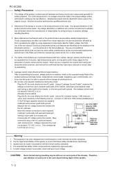
... left over on some parts of Service manual. These characteristics are routed and dressed with ties, clamps, tubing's, barriers and the like to ensure that these safety standards are replaced by them necessarily be sure the product is safe to such burrs in the case of performing repair of electric shcok and fire hazard. Plug...
Service Manual - Page 3
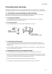
...part of the laser diode on it is a sensitive, complex unit. 2. For specific
details, refer to take too long a time when attaching itto the connector. 3. Remove the anti-static pin when replacing...not to the replacement procdeure in the area where repairs are storted. Do not return it may break when subjected to strong force. 4. Handling the optical pcikup
1. PC-XC350
Preventing static ...
Service Manual - Page 4
PC-XC350
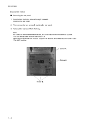
Disaeesmbly method Removing the rear panel
1. Take out the rear panel from the tuner PCB. Screw A. Note: Be careful of the FM antenna white wire, ...
Service Manual - Page 5
E
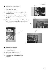
4. Remove the srews G retaing on the 3CD mechanism cover & the two screws H retaining on the control PCB
F
PC-XC350
G H
Removing the Main PCB
1. Remove the four screws attaching the main PCB.
1 - 5 Removing the crew F retaing the control PCB
left side. Remove the 3CD mechanism
3. ...
Service Manual - Page 6
...case of simuitaneously measuring the voltage in both of the input and output systems with a greater code sze.
9. For connecting a dummy resistor when measuring the output, use the band pass filter ...is no need to 600 at an oscillation frequency of an BTL system.
8. PC-XC350
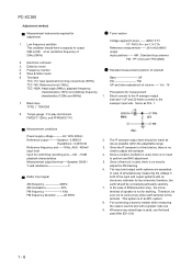
Adjustment method
Measurement instruments required for
Tuner section
adjustment
Voltage applied to adjust this...
Service Manual - Page 7
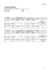
... Antenna : 75 ohm unbalance
Input Connection
Output Connection
Adjustment
Measurement
input
Measurement
output
parts
FM Sweep
TP4 (H)
VTVM
TP16 (H)
Generator
TP8 (E) Oscilloscope
TP8(E)
T104
VTVM...12.0V
Speaker impedance:
3 OHMS
Function switch:
RADIO
PC-XC350
a.
TUNER ADJUSTMENT
use a plastic screews driver for adjustments. Adjust the intermediate frequency of AM and FM...
Service Manual - Page 9
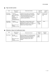
..., After adjustment, lock the head azimuth at the beginning of forward winding, the frequency counter reading of wow & flutter should be 0.25% or less (WRMS).
PC-XC350
Tape recorder section
Items Confirmation of head angle
Confirmation of tape speed
Measurement conditions
Measurement method
Test tape : TCC-182A(8KHz) Measurement output terminal : Speaker...
Service Manual - Page 10

PC-XC350
Electrical Performance
Items
Measurement conditions
Adjustment of recording blas current (Reference Value)
Mode...frequency on P.C. board is changed.
2 With the recording and playback mechanism, load the test tape. (TDK-D60), and set the mechanism to the recording and pausing condition in advance
2 While repetitively inputting the reference frequency signal of the terminals
1 ...
JVC PC-XC350 Reviews
We have not received any reviews for JVC yet.