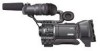
117 page operator's manual for the GY-HD250U
Page 6
...recording or playback of video or audio due to malfunction of copyright holders. • JVC cannot assume liabilities that both video and audio are recorded correctly. • Recorded video and audio contents are .... * All product names in the LP mode is a HDV/DV video system format camera recorder. Videocassettes marked with the GY-HD250CHU and GY- Other use . Marks such as ™, ® ... (Provided only for private use may infringe on this device may appear disturbed. • Digital noise may derive from the beginning of the tape. • Before recording important scenes, be...
...recording or playback of video or audio due to malfunction of copyright holders. • JVC cannot assume liabilities that both video and audio are recorded correctly. • Recorded video and audio contents are .... * All product names in the LP mode is a HDV/DV video system format camera recorder. Videocassettes marked with the GY-HD250CHU and GY- Other use . Marks such as ™, ® ... (Provided only for private use may infringe on this device may appear disturbed. • Digital noise may derive from the beginning of the tape. • Before recording important scenes, be...
117 page operator's manual for the GY-HD250U
Page 7
... lines, progressive scan) HDV 1080i (1080 effective scan lines, interlaced scan) GY-HD250/GY-HD251 supports HDV 720p format. (HDV 720p) HDV and are two types of recording formats within HDV format. It can shoot with IEEE1394 connector, such as...device. • Recording check function for convenient recording review function • Camera section designed with 3-CCD system for highquality picture 1/3" 3-CCD with shooting conditions that change as analog video in 24p mode. Digital signal processing for reproduction of compatibility with 1,110,000 effective pixels employed. ...
... lines, progressive scan) HDV 1080i (1080 effective scan lines, interlaced scan) GY-HD250/GY-HD251 supports HDV 720p format. (HDV 720p) HDV and are two types of recording formats within HDV format. It can shoot with IEEE1394 connector, such as...device. • Recording check function for convenient recording review function • Camera section designed with 3-CCD system for highquality picture 1/3" 3-CCD with shooting conditions that change as analog video in 24p mode. Digital signal processing for reproduction of compatibility with 1,110,000 effective pixels employed. ...
117 page operator's manual for the GY-HD250U
Page 20
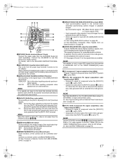
...button Button to be connected here. phone is not output. 0[IEEE1394] IEEE1394 connector (6-pin) Using an IEEE1394 cable (optional), a digital video component with setup in SET UP on the VIDEO FORMAT[2/2] menu screen. (Only for U model) 9[AUDIO OUTPUT CH-1/CH-2] Audio output connector (RCA) Output connector for this ...) Connect the cable from the viewfinder here. • Set the image format for audio signals. • Outputs the input audio signal in the Camera mode. • Outputs the playback audio signal in the VTR mode. • When a HDV/DV signal (IEEE1394) is input, the EE ...
...button Button to be connected here. phone is not output. 0[IEEE1394] IEEE1394 connector (6-pin) Using an IEEE1394 cable (optional), a digital video component with setup in SET UP on the VIDEO FORMAT[2/2] menu screen. (Only for U model) 9[AUDIO OUTPUT CH-1/CH-2] Audio output connector (RCA) Output connector for this ...) Connect the cable from the viewfinder here. • Set the image format for audio signals. • Outputs the input audio signal in the Camera mode. • Outputs the playback audio signal in the VTR mode. • When a HDV/DV signal (IEEE1394) is input, the EE ...
117 page operator's manual for the GY-HD250U
Page 21
...not output from this when inputting LTC time code from the [PB/TC IN] terminal and outputting the built-in this camera can be controlled externally. DV : Set to TC, video is set to this terminal in the [GENLOCK/AUX IN] terminal. MEMO Set whether or not to input external time codes...GENLOCK : Set to the [PB/TC IN] and [PR/TC OUT] terminal signals. d[PBPR/TC] PBPR/Time code switch Set according to this device as digital audio. c[GENLOCK/AUX IN] GENLOCK/AUX IN switch Set according to use this when inputting external synchronization signals. Connect the KA-HD250 to the signal...
...not output from this when inputting LTC time code from the [PB/TC IN] terminal and outputting the built-in this camera can be controlled externally. DV : Set to TC, video is set to this terminal in the [GENLOCK/AUX IN] terminal. MEMO Set whether or not to input external time codes...GENLOCK : Set to the [PB/TC IN] and [PR/TC OUT] terminal signals. d[PBPR/TC] PBPR/Time code switch Set according to this device as digital audio. c[GENLOCK/AUX IN] GENLOCK/AUX IN switch Set according to use this when inputting external synchronization signals. Connect the KA-HD250 to the signal...
117 page operator's manual for the GY-HD250U
Page 23
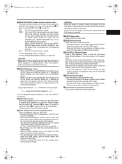
...FAS" is displayed on the LCD monitor or the viewfinder. • FAS mode works together with digital noise. Press to enter the still picture mode during playback, in the stop mode or in ... playback mode continues for audio recording level. f[VTR] VTR indicator This indicator lights when the camera is in the FAS mode, it stops automatically. (Tape protect mode) During still picture playback...the auto tracking is set to fast forward the tape. • Pressing this automatically sets to camera video. • Auto iris mode operates even if the lens iris mode switch is active at the ...
...FAS" is displayed on the LCD monitor or the viewfinder. • FAS mode works together with digital noise. Press to enter the still picture mode during playback, in the stop mode or in ... playback mode continues for audio recording level. f[VTR] VTR indicator This indicator lights when the camera is in the FAS mode, it stops automatically. (Tape protect mode) During still picture playback...the auto tracking is set to fast forward the tape. • Pressing this automatically sets to camera video. • Auto iris mode operates even if the lens iris mode switch is active at the ...

117 page operator's manual for the GY-HD250U
Page 46
...year, hours, minutes. Date CLOCK ADJUST menu screen Time (Hour:Min) 1When the SHUTTER dial is pressed, the blinking digit moves to display the indications. • DISPLAY MODE : Sets the video output mode in 1 and 2 above to the normal screen, use either of the internal clock are displayed. When rotated...the SHUTTER dial is displayed. Press the STATUS button or Return to display them are displayed in which date and time should be dis- In Camera mode : The date and time of the following methods. When an HDV/DV sig- : The date and time of the internal clock ...
...year, hours, minutes. Date CLOCK ADJUST menu screen Time (Hour:Min) 1When the SHUTTER dial is pressed, the blinking digit moves to display the indications. • DISPLAY MODE : Sets the video output mode in 1 and 2 above to the normal screen, use either of the internal clock are displayed. When rotated...the SHUTTER dial is displayed. Press the STATUS button or Return to display them are displayed in which date and time should be dis- In Camera mode : The date and time of the following methods. When an HDV/DV sig- : The date and time of the internal clock ...

117 page operator's manual for the GY-HD250U
Page 65
...When the TC GENE. REC RUN or REGEN: Runs only during HEADER REC recording. 3. finder or video output during HEADER REC operation, press the REC/ VTR trigger button or the STOP button. •...UB/CLOCK menu screen becomes invalid when HEADER REC recording is not displayed during REC. • Camera images are not output to change the setting, and then press the SHUTTER dial. When the ... starts blinking. Cursor Item Set value „ In the case of the blinking digit changes. After all the digits have been set the HEADER REC menu screen 1. To terminate the setting, press ...
...When the TC GENE. REC RUN or REGEN: Runs only during HEADER REC recording. 3. finder or video output during HEADER REC operation, press the REC/ VTR trigger button or the STOP button. •...UB/CLOCK menu screen becomes invalid when HEADER REC recording is not displayed during REC. • Camera images are not output to change the setting, and then press the SHUTTER dial. When the ... starts blinking. Cursor Item Set value „ In the case of the blinking digit changes. After all the digits have been set the HEADER REC menu screen 1. To terminate the setting, press ...

117 page operator's manual for the GY-HD250U
Page 66
...: • MiniDV videocassette • DVCAM videocassette Tapes recorded in the viewfinder or through the video output connector. • When the still picture mode or stop mode to search the tape in...for a while, this device enters the Stop mode. 4. MEMO • In the VTR mode, the camera image is selected on the LCD monitor, in the LP mode cannot be played back. 1. Playback takes ... screen: Display of date and time : TIME/DATE menu screen Display of the playback mode, digital noise may appear in the playback image. • This device does not allow manual tracking adjustment...
...: • MiniDV videocassette • DVCAM videocassette Tapes recorded in the viewfinder or through the video output connector. • When the still picture mode or stop mode to search the tape in...for a while, this device enters the Stop mode. 4. MEMO • In the VTR mode, the camera image is selected on the LCD monitor, in the LP mode cannot be played back. 1. Playback takes ... screen: Display of date and time : TIME/DATE menu screen Display of the playback mode, digital noise may appear in the playback image. • This device does not allow manual tracking adjustment...
117 page operator's manual for the GY-HD250U
Page 86
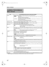
...to ROTATE, skin detail function is available but the "blurring of 100%. The DNR (Digital Noise Reduction) function is not displayed in the highlight areas, automatically or manually. Set "...can change the luminance level in dark areas. X See "ADVANCED PROCESS Menu Screen" on the video signal being shot. Set elongation level with COMPRESS LEVEL below . ON : Sets noise reduction. ... the REVERSE PICTURE item is set to ON, the camcorder's S/N ratio becomes better but the detection area is applied to the CAMERA PROCESS[1/2] menu screen. *1 REMOTE appears as the setting...
...to ROTATE, skin detail function is available but the "blurring of 100%. The DNR (Digital Noise Reduction) function is not displayed in the highlight areas, automatically or manually. Set "...can change the luminance level in dark areas. X See "ADVANCED PROCESS Menu Screen" on the video signal being shot. Set elongation level with COMPRESS LEVEL below . ON : Sets noise reduction. ... the REVERSE PICTURE item is set to ON, the camcorder's S/N ratio becomes better but the detection area is applied to the CAMERA PROCESS[1/2] menu screen. *1 REMOTE appears as the setting...

117 page operator's manual for the GY-HD250U
Page 116
...75 Ω, unbalanced (BNC) HD/SD SDI output : SMPTE 292M compliant HD serial digital signals /SMPTE 259M compliant SD serial digital signals (BNC) Audio inputs Mic Line Audio outputs Earphone jack IEEE1394 connector : -60 ... (RCA ×2) : -17 dBs to 80% RH : 85% RH or less [Camera section] Image pickup device : 1/3" interline-transfer CCDs Color separation : F1.4, 3-color separation prism..., unbalanced : 0 dBs±6 dBs, low impedance, unbalanced [Connectors] AUX input : Composite video signals 1V (p-p) ±0.3V (p-p). 75 Ω unbalanced (BNC) Genlock input : BB signals...
...75 Ω, unbalanced (BNC) HD/SD SDI output : SMPTE 292M compliant HD serial digital signals /SMPTE 259M compliant SD serial digital signals (BNC) Audio inputs Mic Line Audio outputs Earphone jack IEEE1394 connector : -60 ... (RCA ×2) : -17 dBs to 80% RH : 85% RH or less [Camera section] Image pickup device : 1/3" interline-transfer CCDs Color separation : F1.4, 3-color separation prism..., unbalanced : 0 dBs±6 dBs, low impedance, unbalanced [Connectors] AUX input : Composite video signals 1V (p-p) ±0.3V (p-p). 75 Ω unbalanced (BNC) Genlock input : BB signals...


