
Blu-ray disc distribution with ProHD
Page 1
HD content distribution workflow FCP editing/Toast9 BD authoring by PowerMac G5 Acquisition Post Production Distribution GY-HD250 GY-HD200 HDV tape Edit:Final Cut Pro Version6.0.2 Authoring:Roxio Toast9 Titanium IEEE +Plug-in BR-HD50 1394 (AV/C) DR-HD100 Portable Monitor DT...-V9L1DU IEEE 1394 (SBP2) USB2.0 BD drive Lacie d2 BDMV DT-V24L1U DT-V20L1U HDMI BD player 1 Blu-ray disc distribution with ProHD Thanks to FCP ver6.0.2 (NLE) and Toast 9 Titanium (Authoring software) with BD Recorder drive, We can offer complete HD contents distribution workflow with ...
HD content distribution workflow FCP editing/Toast9 BD authoring by PowerMac G5 Acquisition Post Production Distribution GY-HD250 GY-HD200 HDV tape Edit:Final Cut Pro Version6.0.2 Authoring:Roxio Toast9 Titanium IEEE +Plug-in BR-HD50 1394 (AV/C) DR-HD100 Portable Monitor DT...-V9L1DU IEEE 1394 (SBP2) USB2.0 BD drive Lacie d2 BDMV DT-V24L1U DT-V20L1U HDMI BD player 1 Blu-ray disc distribution with ProHD Thanks to FCP ver6.0.2 (NLE) and Toast 9 Titanium (Authoring software) with BD Recorder drive, We can offer complete HD contents distribution workflow with ...

GY-HD250U Studio Monitor/Viewfinder connection & compatibility info.
Page 3
LCD Monitor/Viewfinder connection to KA-HD250 3.VF-P400 Component out SDI out No optional attachment is required SD Yes Yes Yes HD No (letter box) When VF-P400 is set to Y or COMPOSITE in the HDV mode, images are not output from the [Y/PB/PR] terminal. (Images can be output from SDI terminal even in the menu of LCD/VF screen of VF signal in HDV mode.) VF 6-pin KA-V400 20-pin/6-pin converter When this is used, the setting of GY-HD250 should be set to "Y".
LCD Monitor/Viewfinder connection to KA-HD250 3.VF-P400 Component out SDI out No optional attachment is required SD Yes Yes Yes HD No (letter box) When VF-P400 is set to Y or COMPOSITE in the HDV mode, images are not output from the [Y/PB/PR] terminal. (Images can be output from SDI terminal even in the menu of LCD/VF screen of VF signal in HDV mode.) VF 6-pin KA-V400 20-pin/6-pin converter When this is used, the setting of GY-HD250 should be set to "Y".

GY-HD250U Studio Monitor/Viewfinder connection & compatibility info.
Page 5
... of LCD Monitor/Viewfinder connection Type of the Y/PB/PR terminal. *3 SKIN TONE display is only output to the Y terminal of viewfinder Terminal Signal GY-HD250 VF signal HD Signal DV Reverse picture Zebra Display Skin detail range Safety zone Focus assist Provided VF RGB BNCx3 RGB RGB Yes Yes Yes ...No No No VBS BNCx3 Composite Composite Yes Yes Yes Yes No No No Y BNCx1 Y Y Yes Yes Yes Yes No No No *1 Characters from the GY-HD250 are displayed for this line. *2 Signal is not available. Therefore, use the HD/SDSDI terminal output signal for Y/PB/PR terminal output signals.
... of LCD Monitor/Viewfinder connection Type of the Y/PB/PR terminal. *3 SKIN TONE display is only output to the Y terminal of viewfinder Terminal Signal GY-HD250 VF signal HD Signal DV Reverse picture Zebra Display Skin detail range Safety zone Focus assist Provided VF RGB BNCx3 RGB RGB Yes Yes Yes ...No No No VBS BNCx3 Composite Composite Yes Yes Yes Yes No No No Y BNCx1 Y Y Yes Yes Yes Yes No No No *1 Characters from the GY-HD250 are displayed for this line. *2 Signal is not available. Therefore, use the HD/SDSDI terminal output signal for Y/PB/PR terminal output signals.
117 page operator's manual for the GY-HD250U
Page 1
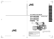
... Enter below the Serial No. Serial No. * The illustration shows the GY-HD250/GYHD251 HD CAMERA RECORDER with the provided lens, viewfinder and microphone attached. LST0440-001B Before operating this JVC product. e_hd250_cover_7.fm Page 1 Tuesday, October 24, 2006 3:13 PM ...© 2006 Victor Company of Japan, Limited GY-HD250/GY-HD251 HD CAMERA RECORDER HD CAMERA RECORDER GY-HD250 INSTRUCTIONS GY-HD251 E INTRODUCTION CONTROLS, INDICATORS AND CONNECTORS...
... Enter below the Serial No. Serial No. * The illustration shows the GY-HD250/GYHD251 HD CAMERA RECORDER with the provided lens, viewfinder and microphone attached. LST0440-001B Before operating this JVC product. e_hd250_cover_7.fm Page 1 Tuesday, October 24, 2006 3:13 PM ...© 2006 Victor Company of Japan, Limited GY-HD250/GY-HD251 HD CAMERA RECORDER HD CAMERA RECORDER GY-HD250 INSTRUCTIONS GY-HD251 E INTRODUCTION CONTROLS, INDICATORS AND CONNECTORS...
117 page operator's manual for the GY-HD250U
Page 6
...Marks such as ™, ® and © are not used . Information applicable only to the GY-HD250U/CHU is marked by "(U model only)". Videocassettes marked with the GY-HD250CHU and GY- Recording or playback in the SP mode. e_hd250.book Page 2 Tuesday, October 24, 2006 3:11 PM...GY-HD250U/CHU and GYHD251E/CHE. • A lens is included with the GY-HD250U and GY-HD251E. • A lens is a HDV/DV video system format camera recorder. HD251CHE. The following phenomena may infringe on other units (including another GY-HD250/GY-HD251) are for purchasing the JVC GY-HD250U/CHU and GY...
...Marks such as ™, ® and © are not used . Information applicable only to the GY-HD250U/CHU is marked by "(U model only)". Videocassettes marked with the GY-HD250CHU and GY- Recording or playback in the SP mode. e_hd250.book Page 2 Tuesday, October 24, 2006 3:11 PM...GY-HD250U/CHU and GYHD251E/CHE. • A lens is included with the GY-HD250U and GY-HD251E. • A lens is a HDV/DV video system format camera recorder. HD251CHE. The following phenomena may infringe on other units (including another GY-HD250/GY-HD251) are for purchasing the JVC GY-HD250U/CHU and GY...
117 page operator's manual for the GY-HD250U
Page 7
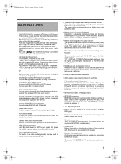
...video on Mini DV videocassettes. HDV 720p (720 effective scan lines, progressive scan) HDV 1080i (1080 effective scan lines, interlaced scan) GY-HD250/GY-HD251 supports HDV 720p format. (HDV 720p) HDV and are two types of digital data to suit the shooting conditions. •...CCD system for troublesome switch or filter operations by connecting to HDV/DV devices. • Connect to KA-HD250 Studio Kit and use as a studio camera. 3 Enables transfer of recording formats within HDV format. e_hd250.book Page 3 Tuesday, October 24, 2006 3:11 PM MAIN FEATURES • GY-HD250/GY...
...video on Mini DV videocassettes. HDV 720p (720 effective scan lines, progressive scan) HDV 1080i (1080 effective scan lines, interlaced scan) GY-HD250/GY-HD251 supports HDV 720p format. (HDV 720p) HDV and are two types of digital data to suit the shooting conditions. •...CCD system for troublesome switch or filter operations by connecting to HDV/DV devices. • Connect to KA-HD250 Studio Kit and use as a studio camera. 3 Enables transfer of recording formats within HDV format. e_hd250.book Page 3 Tuesday, October 24, 2006 3:11 PM MAIN FEATURES • GY-HD250/GY...
117 page operator's manual for the GY-HD250U
Page 11
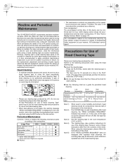
...mechanisms also collect dirt. If an M-DV80 tape is used for periodical head cleaning. Avoid excessive repeated use cleaning tape produced by JVC. However, cleaning with the hour meter display (which shows the accumulated drum and fan motor running time). Block Noise • ... maintain beautiful pictures and sound, be abnormal. e_hd250.book Page 7 Tuesday, October 24, 2006 3:11 PM Routine and Periodical Maintenance The GY-HD250/GY-HD251 incorporates precision mechanical parts, which will collect dirt, wear out and deteriorate as this device is used in a low humidity environment, ...
...mechanisms also collect dirt. If an M-DV80 tape is used for periodical head cleaning. Avoid excessive repeated use cleaning tape produced by JVC. However, cleaning with the hour meter display (which shows the accumulated drum and fan motor running time). Block Noise • ... maintain beautiful pictures and sound, be abnormal. e_hd250.book Page 7 Tuesday, October 24, 2006 3:11 PM Routine and Periodical Maintenance The GY-HD250/GY-HD251 incorporates precision mechanical parts, which will collect dirt, wear out and deteriorate as this device is used in a low humidity environment, ...

117 page operator's manual for the GY-HD250U
Page 12
... in a horizontal position, pressure from humidity, dust and ultraviolet light. Keep tapes in the environment below. Videocassette to be Used • Use JVC's videocassette tapes marked with the A symbol. • Mini DV videocassette : M-DV63HD M-DV63PROHD * Do not use , store them lying flat....When housed in distortion of the tape edges. 8 If videotapes are not in use M-DV80. • Videocassettes cannot be Used The GY-HD250/GY-HD251 can cause distortions and deformations of the tape. e_hd250.book Page 8 Tuesday, October 24, 2006 3:11 PM INTRODUCTION Battery Pack to...
... in a horizontal position, pressure from humidity, dust and ultraviolet light. Keep tapes in the environment below. Videocassette to be Used • Use JVC's videocassette tapes marked with the A symbol. • Mini DV videocassette : M-DV63HD M-DV63PROHD * Do not use , store them lying flat....When housed in distortion of the tape edges. 8 If videotapes are not in use M-DV80. • Videocassettes cannot be Used The GY-HD250/GY-HD251 can cause distortions and deformations of the tape. e_hd250.book Page 8 Tuesday, October 24, 2006 3:11 PM INTRODUCTION Battery Pack to...
117 page operator's manual for the GY-HD250U
Page 15
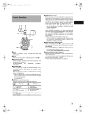
... the lamp should light and the lighting pattern. X See "Attaching the Zoom Lens" on page 33. 4Front tally lamp This lamp lights up when the GY-HD250/GY-HD251 enters the record mode. The luminance level can be changed with the ZEBRA setting in accordance with the SKIN COLOR ADJUST item on the...
... the lamp should light and the lighting pattern. X See "Attaching the Zoom Lens" on page 33. 4Front tally lamp This lamp lights up when the GY-HD250/GY-HD251 enters the record mode. The luminance level can be changed with the ZEBRA setting in accordance with the SKIN COLOR ADJUST item on the...
117 page operator's manual for the GY-HD250U
Page 16
...on the OTHERS[1/2] menu screen to this device as possible, as shown in the figure. 1 2 3 4 1Back tally lamp This lamp lights up when the GY-HD250/GY-HD251 enters the record mode. Set the AUDIO MONITOR item on page 19 to the record mode. It blinks during the transition to BOTH. Set... screen. • When using a stereotype jack and stereo sound should be output, the following : • Menu Setting screens • Characters showing the whether the GY-HD250/GYHD251 is set with the AUDIO MONITOR item on the AUDIO/MIC[2/2] menu screen and MONITOR SELECT switch d on page 14.
...on the OTHERS[1/2] menu screen to this device as possible, as shown in the figure. 1 2 3 4 1Back tally lamp This lamp lights up when the GY-HD250/GY-HD251 enters the record mode. Set the AUDIO MONITOR item on page 19 to the record mode. It blinks during the transition to BOTH. Set... screen. • When using a stereotype jack and stereo sound should be output, the following : • Menu Setting screens • Characters showing the whether the GY-HD250/GYHD251 is set with the AUDIO MONITOR item on the AUDIO/MIC[2/2] menu screen and MONITOR SELECT switch d on page 14.
117 page operator's manual for the GY-HD250U
Page 22
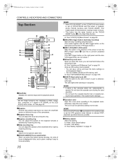
... is pressed in the Camera mode to set to insert or eject a videocassette tape. Use this to prevent unwanted recording. (The REC trigger button on GY-HD250/GY-HD251. • You can insert and remove the SD memory card. bOperation cover Open this switch to the side to ACCU-FOCUS and this button...
... is pressed in the Camera mode to set to insert or eject a videocassette tape. Use this to prevent unwanted recording. (The REC trigger button on GY-HD250/GY-HD251. • You can insert and remove the SD memory card. bOperation cover Open this switch to the side to ACCU-FOCUS and this button...

117 page operator's manual for the GY-HD250U
Page 36
...FUJINON) Microphone GY-HD250/GY-HD251 IEEE1394 Cable 6P-6P For GY-HD250 Wide Converter ...WCV-82SC Focus Manual Unit *1 Zoom Servo Unit HZ-ZS13B 1/3 Zoom Lens Th16 × 5.5BRMU (FUJINON) (Excluding the CHU/CHE model) MACRO VF BRIGHT USER 1 USER 2 USER 3 ND FILTER 2 1 MENU STATUS WHT.BAL AUTO AUTO AUDIO CH-1 LEVEL CH-2 ON OFF POWER REC SD Memory Card Battery mount GY-HD250...: Gold Mount GY-HD251: V Mount Anton Bauer Battery Anton Bauer Battery Charger For GY-HD251 GY-HD250/GY...Electronics) Studio Kit KA-HD250 *1 An HZ-FM13 cannot be ...
...FUJINON) Microphone GY-HD250/GY-HD251 IEEE1394 Cable 6P-6P For GY-HD250 Wide Converter ...WCV-82SC Focus Manual Unit *1 Zoom Servo Unit HZ-ZS13B 1/3 Zoom Lens Th16 × 5.5BRMU (FUJINON) (Excluding the CHU/CHE model) MACRO VF BRIGHT USER 1 USER 2 USER 3 ND FILTER 2 1 MENU STATUS WHT.BAL AUTO AUTO AUDIO CH-1 LEVEL CH-2 ON OFF POWER REC SD Memory Card Battery mount GY-HD250...: Gold Mount GY-HD251: V Mount Anton Bauer Battery Anton Bauer Battery Charger For GY-HD251 GY-HD250/GY...Electronics) Studio Kit KA-HD250 *1 An HZ-FM13 cannot be ...

117 page operator's manual for the GY-HD250U
Page 37
... phantom microphone. 1. Place the microphone toward the front to prevent it in the lens dropping off or disturbed back focus. • Set the GY-HD250/GY-HD251's power switch to a comfortable position and then turn the slide mounting ring and mount. „ To take off the viewfinder 2. To...the microphone holder. Clamp Clamp CAUTION • Be sure to perform the correct setting for use of the arrow. 2. Turn the knob on the GY-HD250/GY-HD251. 5. Turn the knob on the microphone holder clockwise to Attach the Viewfinder 1. Loosen the mount ring. 2. INPUT1, 2 connector How to secure...
... phantom microphone. 1. Place the microphone toward the front to prevent it in the lens dropping off or disturbed back focus. • Set the GY-HD250/GY-HD251's power switch to a comfortable position and then turn the slide mounting ring and mount. „ To take off the viewfinder 2. To...the microphone holder. Clamp Clamp CAUTION • Be sure to perform the correct setting for use of the arrow. 2. Turn the knob on the GY-HD250/GY-HD251. 5. Turn the knob on the microphone holder clockwise to Attach the Viewfinder 1. Loosen the mount ring. 2. INPUT1, 2 connector How to secure...

117 page operator's manual for the GY-HD250U
Page 38
... 7 on page 100. X See "FILE MANAGE Menu Screen" on page 14. Face the cutout end of the SD memory card inward and insert it on GY-HD250/GY-HD251. LOCK switch MEMO SDHC-compliant memory cards cannot be sure to attach the provided core filter as shown in the figure below. • Attach... just purchased or formatted on the side of the arrow. • The SD memory card comes out slightly. 2. Set the switch on a device other than GY-HD250/ GY-HD251, format it in the direction of unwanted radio waves, be used with this device as shown in the direction of the SD memory card...
... 7 on page 100. X See "FILE MANAGE Menu Screen" on page 14. Face the cutout end of the SD memory card inward and insert it on GY-HD250/GY-HD251. LOCK switch MEMO SDHC-compliant memory cards cannot be sure to attach the provided core filter as shown in the figure below. • Attach... just purchased or formatted on the side of the arrow. • The SD memory card comes out slightly. 2. Set the switch on a device other than GY-HD250/ GY-HD251, format it in the direction of unwanted radio waves, be used with this device as shown in the direction of the SD memory card...

117 page operator's manual for the GY-HD250U
Page 40
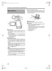
...the amount of unnecessary radio waves emitted, attach a provided Clamp filter near both ends of the GY-HD250/GY-HD251 to the GY-HD250/GY-HD251 and an AC outlet or mount a charged battery on the GY-HD250/GY-HD251 to either of the positions). 3. Leave the equipment in this case, recharge the built-...• Do not remove or connect the DC cable while recording is disconnected from a power supply. However, it gradually discharges while the GY-HD250/GY-HD251 is being charged for about 4 hours. Power is operable with AC power supply or battery pack. Clamp filter DC INPUT IEEE 1394...
...the amount of unnecessary radio waves emitted, attach a provided Clamp filter near both ends of the GY-HD250/GY-HD251 to the GY-HD250/GY-HD251 and an AC outlet or mount a charged battery on the GY-HD250/GY-HD251 to either of the positions). 3. Leave the equipment in this case, recharge the built-...• Do not remove or connect the DC cable while recording is disconnected from a power supply. However, it gradually discharges while the GY-HD250/GY-HD251 is being charged for about 4 hours. Power is operable with AC power supply or battery pack. Clamp filter DC INPUT IEEE 1394...
117 page operator's manual for the GY-HD250U
Page 42
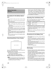
...: Blinks „ Monitoring loudspeaker and PHONES jack: Alarm sound MEMO • After the remaining battery power warnings appear, the GY-HD250/GY-HD251 automatically stops operation if the battery power operation is continued. 38 Recharging • Recharge the battery pack after the DC ...battery, the remaining battery (capacity or time) can be used frequently. Audio signal are used . Remove the battery pack when the GY-HD250/GY-HD251 is reduced by repeating incomplete recharging, or recharging without discharging, once discharge the battery pack completely, then recharge it might be...
...: Blinks „ Monitoring loudspeaker and PHONES jack: Alarm sound MEMO • After the remaining battery power warnings appear, the GY-HD250/GY-HD251 automatically stops operation if the battery power operation is continued. 38 Recharging • Recharge the battery pack after the DC ...battery, the remaining battery (capacity or time) can be used frequently. Audio signal are used . Remove the battery pack when the GY-HD250/GY-HD251 is reduced by repeating incomplete recharging, or recharging without discharging, once discharge the battery pack completely, then recharge it might be...

117 page operator's manual for the GY-HD250U
Page 43
...3:11 PM PREPARATIONS FOR OPERATION Turning the Power ON Turning the Power ON 1. HDV/DV input is loaded, the GY-HD250/GY-HD251 enters the record-standby mode automatically. Place the GY-HD250/GY-HD251 in the viewfinder. Set the POWER switch to ON. When a videocassette is in the Camera mode or in ...switch accidentally be displayed in the viewfinder. This device turns on the LCD monitor. Set the POWER switch to OFF. 3. VTR mode The GY-HD250/GY-HD251 enters the VTR mode. "STOP" is displayed in the VTR operation mode indication area of the LCD monitor and/or in the ...
...3:11 PM PREPARATIONS FOR OPERATION Turning the Power ON Turning the Power ON 1. HDV/DV input is loaded, the GY-HD250/GY-HD251 enters the record-standby mode automatically. Place the GY-HD250/GY-HD251 in the viewfinder. Set the POWER switch to ON. When a videocassette is in the Camera mode or in ...switch accidentally be displayed in the viewfinder. This device turns on the LCD monitor. Set the POWER switch to OFF. 3. VTR mode The GY-HD250/GY-HD251 enters the VTR mode. "STOP" is displayed in the VTR operation mode indication area of the LCD monitor and/or in the ...
117 page operator's manual for the GY-HD250U
Page 47
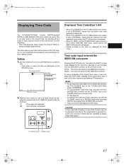
... displayed. item on the STATUS screen. TC DISPLAY switch TC GENE. e_hd250.book Page 43 Tuesday, October 24, 2006 3:11 PM Displaying Time Code The GY-HD250/GY-HD251 records SMPTE-standard (NTSC) or EBU-standard (PAL) time codes and user's bits. minal or [HD/SD-SDI] terminal. The time codes or user...
... displayed. item on the STATUS screen. TC DISPLAY switch TC GENE. e_hd250.book Page 43 Tuesday, October 24, 2006 3:11 PM Displaying Time Code The GY-HD250/GY-HD251 records SMPTE-standard (NTSC) or EBU-standard (PAL) time codes and user's bits. minal or [HD/SD-SDI] terminal. The time codes or user...

117 page operator's manual for the GY-HD250U
Page 51
.... To enable this device enters record mode from the [HD/SD-SDI] terminal. Playback continues. • When a tape with special operations. item on Tape The GY-HD250/GY-HD251 also incorporates a time code reader. e_hd250.book Page 47 Tuesday, October 24, 2006 3:11 PM Recording Time Codes in Continuation of Time Codes Recorded...
.... To enable this device enters record mode from the [HD/SD-SDI] terminal. Playback continues. • When a tape with special operations. item on Tape The GY-HD250/GY-HD251 also incorporates a time code reader. e_hd250.book Page 47 Tuesday, October 24, 2006 3:11 PM Recording Time Codes in Continuation of Time Codes Recorded...

117 page operator's manual for the GY-HD250U
Page 60
... INPUT1 or INPUT2 connector. nel whose audio level that the peak level does not exceed the -3 dB point when a loud sound is input. The GY-HD250/GY-HD251 is provided with the INPUT1 connector and the INPUT2 connector for the audio to this position when using the AUDIO INPUT switch. CH-2 INPUT... 56 Tuesday, October 24, 2006 3:11 PM SETTING AND ADJUSTMENTS BEFORE SHOOTING Audio Input Signal Selection MEMO You can be adjusted manually when the GYHD250/GY-HD251 is in the record, record-standby or stop mode. 1. FREE REC REGEN ON OFF POWER REC CH-1 audio input level volume CH-1/CH-2...
... INPUT1 or INPUT2 connector. nel whose audio level that the peak level does not exceed the -3 dB point when a loud sound is input. The GY-HD250/GY-HD251 is provided with the INPUT1 connector and the INPUT2 connector for the audio to this position when using the AUDIO INPUT switch. CH-2 INPUT... 56 Tuesday, October 24, 2006 3:11 PM SETTING AND ADJUSTMENTS BEFORE SHOOTING Audio Input Signal Selection MEMO You can be adjusted manually when the GYHD250/GY-HD251 is in the record, record-standby or stop mode. 1. FREE REC REGEN ON OFF POWER REC CH-1 audio input level volume CH-1/CH-2...


