

45 pg user manual for BR-DV600U/E VTR (1130KB)
Page 4
...unit is necessary to prevent malfunctions and maintain the performance level required for use as a recorder/player. After cleaning the heads, check that it with clogged heads may lead to malfunctions.... the MiniDV mark. ogy 5 DV in/out (IEEE 1394) connector enabling signals to be transferred to or from TV broadcast programs or pre-recorded programs without maintenance may result in...- Details for professional use of the VCR without the consent of the owner of copyright, except in cases where this material is no lip link shift even during extended recording 5 JVC bus and RS...
...unit is necessary to prevent malfunctions and maintain the performance level required for use as a recorder/player. After cleaning the heads, check that it with clogged heads may lead to malfunctions.... the MiniDV mark. ogy 5 DV in/out (IEEE 1394) connector enabling signals to be transferred to or from TV broadcast programs or pre-recorded programs without maintenance may result in...- Details for professional use of the VCR without the consent of the owner of copyright, except in cases where this material is no lip link shift even during extended recording 5 JVC bus and RS...
45 pg user manual for BR-DV600U/E VTR (1130KB)
Page 5
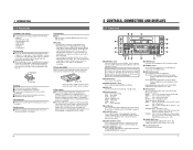
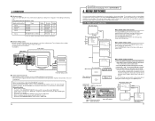
... not use when plugging or unplugging the power supply. 6 2 CONTROLS, CONNECTORS AND DISPLAYS 2-1 Front Panel #$ % OPERATE CH-1/3 VIDEO CASSETTE RECORDER BR-DV600U ON/OFF 1 @ REC LEVEL EJECT 2 MENU ADVANCE PRESET CH-2/4 REC PLAY PAUSE ! 0 SHIFT SHIFT HOLD SHIFT A. If the ...MENU H M S F REMOTE REW STOP FF LOCAL MIC 3 4 AUDIO 987 6 5 1 [OPERATE] switch Press this VCR. 5 Handling • Cassette tapes cannot be adjusted in normal recording. For editing over an extended period, it as dropouts) may also shorten the service life of the rotary heads. •...
... not use when plugging or unplugging the power supply. 6 2 CONTROLS, CONNECTORS AND DISPLAYS 2-1 Front Panel #$ % OPERATE CH-1/3 VIDEO CASSETTE RECORDER BR-DV600U ON/OFF 1 @ REC LEVEL EJECT 2 MENU ADVANCE PRESET CH-2/4 REC PLAY PAUSE ! 0 SHIFT SHIFT HOLD SHIFT A. If the ...MENU H M S F REMOTE REW STOP FF LOCAL MIC 3 4 AUDIO 987 6 5 1 [OPERATE] switch Press this VCR. 5 Handling • Cassette tapes cannot be adjusted in normal recording. For editing over an extended period, it as dropouts) may also shorten the service life of the rotary heads. •...
45 pg user manual for BR-DV600U/E VTR (1130KB)
Page 7
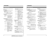
... system has stabilized. MENU: Lights in the menu switch setting mode. 32K/44.1K/48K: Shows the frequency of the signal output from a VCR, etc. The 44.1K indication is not a malfunction. 11 Indication and output signals can be switched with the No. 003 menu switch set ... the No. 003 menu switch setting and operation mode. Monitor TV Connecting a monitor The on a monitor connected to the DV IN/OUT connector, distortion may appear in the Recording mode and EE mode. The sub carrier cannot be viewed on -screen display can be locked. • Plugging and unplugging ...
... system has stabilized. MENU: Lights in the menu switch setting mode. 32K/44.1K/48K: Shows the frequency of the signal output from a VCR, etc. The 44.1K indication is not a malfunction. 11 Indication and output signals can be switched with the No. 003 menu switch set ... the No. 003 menu switch setting and operation mode. Monitor TV Connecting a monitor The on a monitor connected to the DV IN/OUT connector, distortion may appear in the Recording mode and EE mode. The sub carrier cannot be viewed on -screen display can be locked. • Plugging and unplugging ...
45 pg user manual for BR-DV600U/E VTR (1130KB)
Page 8
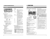
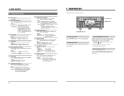
...on page 24. 5 Digital inputs Digital signals conforming to IEEE 1394 are available). Recording on the monitor. The unit may not operate properly. The selected audio channel is displayed. DV Analog audio (2 channels) DV IN/OUT VIDEO LINE COMPONENT Y/C IN R-Y B-Y Y AUDIO CH 1/3 CH ...MONITOR OUT SYNC IN TIME CODE SPARE TIMER SERIAL REC PLAY DC 12V OFF Headphones Mic DV Analog audio (2 channels) Audio input to record 4 channels simultaneously. Adjust the audio volume level with the VCR ON. Type of connector 1 [SERIAL] connector 2 [REMOTE1] connector 3 [REMOTE2] ...
...on page 24. 5 Digital inputs Digital signals conforming to IEEE 1394 are available). Recording on the monitor. The unit may not operate properly. The selected audio channel is displayed. DV Analog audio (2 channels) DV IN/OUT VIDEO LINE COMPONENT Y/C IN R-Y B-Y Y AUDIO CH 1/3 CH ...MONITOR OUT SYNC IN TIME CODE SPARE TIMER SERIAL REC PLAY DC 12V OFF Headphones Mic DV Analog audio (2 channels) Audio input to record 4 channels simultaneously. Adjust the audio volume level with the VCR ON. Type of connector 1 [SERIAL] connector 2 [REMOTE1] connector 3 [REMOTE2] ...
45 pg user manual for BR-DV600U/E VTR (1130KB)
Page 9
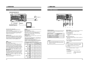
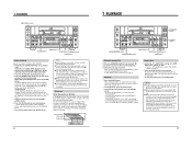
... DC 12V OFF DV IN/OUT VIDEO ...PLAYER COUNTER RESET EJECT RECORDER...PLAYER P STOP STILL RECORDER...BR-DV600U cannot be used as a recorder, the following editing operations are trademarks. The S-VHS/VHS VCR...VCR) can be replaced with a D-9/Betacam VCR. Otherwise, the VCR may be degraded. • Use the RM-G800 with the RM-G800, the BR-DV600's preroll operation is comparatively slow. When the BR-DV600U is used as a recorder VCR...recorder VCR...RECORDER...X1 REV PLAYER FWD MIN ... DURATION PLAYER EJECT ...BR-DV600U as a feeder/player with another MiniDV VCR...BR-DV600U can be used as...
... DC 12V OFF DV IN/OUT VIDEO ...PLAYER COUNTER RESET EJECT RECORDER...PLAYER P STOP STILL RECORDER...BR-DV600U cannot be used as a recorder, the following editing operations are trademarks. The S-VHS/VHS VCR...VCR) can be replaced with a D-9/Betacam VCR. Otherwise, the VCR may be degraded. • Use the RM-G800 with the RM-G800, the BR-DV600's preroll operation is comparatively slow. When the BR-DV600U is used as a recorder VCR...recorder VCR...RECORDER...X1 REV PLAYER FWD MIN ... DURATION PLAYER EJECT ...BR-DV600U as a feeder/player with another MiniDV VCR...BR-DV600U can be used as...
45 pg user manual for BR-DV600U/E VTR (1130KB)
Page 10
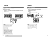
...: Changes the setting. Setting table (when the RM-G800 is used for control, assemble editing cannot be performed. • When the VCR is stopped via the DV connector, a command error message may be returned to each menu switch item is restored. SR-S365 (U MODEL) --SR-S388 (E MODEL... recorder Set the No. 108 menu switch to end menu switch setting. [The set switches using either the on -screen display. Menu switch setting screen To access this switch is used ) Signal connection method Analog IEEE 1394 Analog Analog Player BR-DV600 BR-DV600 BR-DV600 BR-DV600 Analog BR-S800/BR-...
...: Changes the setting. Setting table (when the RM-G800 is used for control, assemble editing cannot be performed. • When the VCR is stopped via the DV connector, a command error message may be returned to each menu switch item is restored. SR-S365 (U MODEL) --SR-S388 (E MODEL... recorder Set the No. 108 menu switch to end menu switch setting. [The set switches using either the on -screen display. Menu switch setting screen To access this switch is used ) Signal connection method Analog IEEE 1394 Analog Analog Player BR-DV600 BR-DV600 BR-DV600 BR-DV600 Analog BR-S800/BR-...
45 pg user manual for BR-DV600U/E VTR (1130KB)
Page 11
...(01): Allows control of this unit with the controller connected to the [REMOTE 2] and [DV IN/ OUT] connectors. JVC BUS + IEEE 1394 (09): Allows control of this unit with the controller connected to play back a tape recorded on page 16. qJVC BUS + RS232C + 1394 (11): Allows control of this unit ...playback start point is delayed by 7 frames. 360 AUTO REW AT TIMER Details: Selects whether or not the tape is automatically rewound when the VCR power is switched ON in point is set value on the rear panel. Setting: q0F: No compensation. 1F: The playback start point is delayed...
...(01): Allows control of this unit with the controller connected to the [REMOTE 2] and [DV IN/ OUT] connectors. JVC BUS + IEEE 1394 (09): Allows control of this unit with the controller connected to play back a tape recorded on page 16. qJVC BUS + RS232C + 1394 (11): Allows control of this unit ...playback start point is delayed by 7 frames. 360 AUTO REW AT TIMER Details: Selects whether or not the tape is automatically rewound when the VCR power is switched ON in point is set value on the rear panel. Setting: q0F: No compensation. 1F: The playback start point is delayed...
45 pg user manual for BR-DV600U/E VTR (1130KB)
Page 12
... etc. Setting: DATE (00): Shows the date. DATE+CLOCK (02): Shows the date and time. CH-1/3 REC LEVEL VIDEO CASSETTE RECORDER BR-DV600U OPERATE ON/OFF EJECT CH-2/4 MENU ADVANCE PRESET SHIFT SHIFT HOLD SHIFT A. Loading/unloading a cassette Insert the cassette into the cassette loading...minute after the fan motor stops. Setting: qPRESET (00): Engages the Preset mode. Turn the power OFF Press the [OPERATE] switch. DISABLE (01): The VCR continues operation even after the fan motor stops. horizontally. Setting: 0 (00) The display position can be moved in q 1 (01) 12 steps from ...
... etc. Setting: DATE (00): Shows the date. DATE+CLOCK (02): Shows the date and time. CH-1/3 REC LEVEL VIDEO CASSETTE RECORDER BR-DV600U OPERATE ON/OFF EJECT CH-2/4 MENU ADVANCE PRESET SHIFT SHIFT HOLD SHIFT A. Loading/unloading a cassette Insert the cassette into the cassette loading...minute after the fan motor stops. Setting: qPRESET (00): Engages the Preset mode. Turn the power OFF Press the [OPERATE] switch. DISABLE (01): The VCR continues operation even after the fan motor stops. horizontally. Setting: 0 (00) The display position can be moved in q 1 (01) 12 steps from ...

45 pg user manual for BR-DV600U/E VTR (1130KB)
Page 13
... data. 22 6 RECORDING [REC LEVEL] control CH-1/3 REC LEVEL VIDEO CASSETTE RECORDER BR-DV600U OPERATE ON/OFF EJECT CH-2/4 MENU ADVANCE PRESET SHIFT SHIFT HOLD SHIFT A. To stop recording. MENU ADVANCE PRESET ADVANCE... [REC LEVEL] control. COMPONENT: Selects the component video signals input to the [DV IN/OUT] connector. IEEE 1394: Selects the digital video signals and the digital audio...recording, press the [PLAY] button. In the Play mode, this unit is played back on a consumer MiniDV VCR, the sound level may be low. 5 During recording, the upper section of the tape during recording...
... data. 22 6 RECORDING [REC LEVEL] control CH-1/3 REC LEVEL VIDEO CASSETTE RECORDER BR-DV600U OPERATE ON/OFF EJECT CH-2/4 MENU ADVANCE PRESET SHIFT SHIFT HOLD SHIFT A. To stop recording. MENU ADVANCE PRESET ADVANCE... [REC LEVEL] control. COMPONENT: Selects the component video signals input to the [DV IN/OUT] connector. IEEE 1394: Selects the digital video signals and the digital audio...recording, press the [PLAY] button. In the Play mode, this unit is played back on a consumer MiniDV VCR, the sound level may be low. 5 During recording, the upper section of the tape during recording...
45 pg user manual for BR-DV600U/E VTR (1130KB)
Page 14
... To stop Repeat Play, press the [STOP] button. If another BR-DV600), sound and picture may be distorted. 5 During audio dubbing, noise might be engaged unless the VCR is shown and the VCR enters the Stop mode. 4 Adjust the audio recording level with the [REC LEVEL] control. 5 Press the [PLAY... CH1/2 playback signal on another VCR (including another tape is rewound automatically and playback starts again. Sub code area Video area Audio area 48k CH1 CH2 32k CH1/CH2 CH3/CH4 7 PLAYBACK CH-1/3 REC LEVEL VIDEO CASSETTE RECORDER BR-DV600U OPERATE ON/OFF EJECT CH-2/4 MENU ADVANCE PRESET ...
... To stop Repeat Play, press the [STOP] button. If another BR-DV600), sound and picture may be distorted. 5 During audio dubbing, noise might be engaged unless the VCR is shown and the VCR enters the Stop mode. 4 Adjust the audio recording level with the [REC LEVEL] control. 5 Press the [PLAY... CH1/2 playback signal on another VCR (including another tape is rewound automatically and playback starts again. Sub code area Video area Audio area 48k CH1 CH2 32k CH1/CH2 CH3/CH4 7 PLAYBACK CH-1/3 REC LEVEL VIDEO CASSETTE RECORDER BR-DV600U OPERATE ON/OFF EJECT CH-2/4 MENU ADVANCE PRESET ...
45 pg user manual for BR-DV600U/E VTR (1130KB)
Page 15
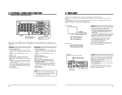
...Insert a cassette. 5 Set the rear panel's [TIMER] switch to "PLAY". 4 When power is supplied, the VCR automatically enters the Record mode. Using the menu switches, you can be recorded on -screen display HOLD: Start SHIFT: Moves the cursor to the counter display indications. All time code data including ... cable plug to this unit ON with the materials to "TC" or "UB". 8 EXTERNAL TIMER-START FUNCTION (AUTOMATIC START-UP WITH POWER SUPPLY) DV IN/OUT VIDEO LINE COMPONENT Y/C IN R-Y B-Y Y AUDIO CH 1/3 CH 2/4 IN IN OUT PGZ01945 OUT OUT MONITOR OUT 1 REMOTE 2 MONITOR ...
...Insert a cassette. 5 Set the rear panel's [TIMER] switch to "PLAY". 4 When power is supplied, the VCR automatically enters the Record mode. Using the menu switches, you can be recorded on -screen display HOLD: Start SHIFT: Moves the cursor to the counter display indications. All time code data including ... cable plug to this unit ON with the materials to "TC" or "UB". 8 EXTERNAL TIMER-START FUNCTION (AUTOMATIC START-UP WITH POWER SUPPLY) DV IN/OUT VIDEO LINE COMPONENT Y/C IN R-Y B-Y Y AUDIO CH 1/3 CH 2/4 IN IN OUT PGZ01945 OUT OUT MONITOR OUT 1 REMOTE 2 MONITOR ...
45 pg user manual for BR-DV600U/E VTR (1130KB)
Page 16
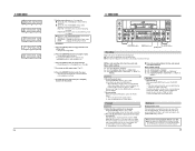
... from the preset data. 5 Time code recording follows the time code already recorded on -screen display and counter display. LTC time code is not necessary for user bits. On the on a consumer MiniDV VCR), the user bits that were played back last will be displayed. Menu switch setting No... RUN" or "FREE RUN" No. 416 "NON DROP" or "DROP" (U MODEL) Operation 1 Start recording. During playback, the data in the Stop mode. 28 9 TIME CODE CH-1/3 REC LEVEL VIDEO CASSETTE RECORDER BR-DV600U OPERATE ON/OFF EJECT CH-2/4 MENU ADVANCE PRESET SHIFT SHIFT HOLD SHIFT A. Note on time code...
... from the preset data. 5 Time code recording follows the time code already recorded on -screen display and counter display. LTC time code is not necessary for user bits. On the on a consumer MiniDV VCR), the user bits that were played back last will be displayed. Menu switch setting No... RUN" or "FREE RUN" No. 416 "NON DROP" or "DROP" (U MODEL) Operation 1 Start recording. During playback, the data in the Stop mode. 28 9 TIME CODE CH-1/3 REC LEVEL VIDEO CASSETTE RECORDER BR-DV600U OPERATE ON/OFF EJECT CH-2/4 MENU ADVANCE PRESET SHIFT SHIFT HOLD SHIFT A. Note on time code...
45 pg user manual for BR-DV600U/E VTR (1130KB)
Page 17
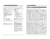
... STATUS SENSE CURRENT TC SENSE CURRENT CTL SENSE TIMER MODE SELECT JVC TABLE 1 ON JVC BASIC TABLE ON REC/ DUB REQUEST VTR IND JVC STATUS MEMORY SW SENSE PRESET 31 Preparation Connect the 9-pin D-sub connector of the recording VCR 2. For RS-232C interface settings, refer to "RS232C", "IEEE... 1394+ RS232C", "JVC BUS + RS232C" or "JVC BUS + RS232C + 1394". Set the No. 050 menu switch to "RS-232C specifications" on page 32. ...
... STATUS SENSE CURRENT TC SENSE CURRENT CTL SENSE TIMER MODE SELECT JVC TABLE 1 ON JVC BASIC TABLE ON REC/ DUB REQUEST VTR IND JVC STATUS MEMORY SW SENSE PRESET 31 Preparation Connect the 9-pin D-sub connector of the recording VCR 2. For RS-232C interface settings, refer to "RS232C", "IEEE... 1394+ RS232C", "JVC BUS + RS232C" or "JVC BUS + RS232C + 1394". Set the No. 050 menu switch to "RS-232C specifications" on page 32. ...

45 pg user manual for BR-DV600U/E VTR (1130KB)
Page 18
... computer. AE R-FIELD STEP Reverses one frame. When the tape is cued, COMPLETION is returned and the Play mode is received correctly, the VCR returns ACK (OAh) and enters the mode corresponding to cue up a specified point on the tape. AD F-FIELD STEP Advances one frame.... 10 33 This command should be transmitted in this command (see the table below). These commands are used to "RS232C", "IEEE 1394 + RS232C", "JVC BUS + RS232C" or "JVC BUS + RS232C + 1394". This command should be installed in the Play-Pause mode. When the tape is cued, COMPLETION is returned and the Pause...
... computer. AE R-FIELD STEP Reverses one frame. When the tape is cued, COMPLETION is returned and the Play mode is received correctly, the VCR returns ACK (OAh) and enters the mode corresponding to cue up a specified point on the tape. AD F-FIELD STEP Advances one frame.... 10 33 This command should be transmitted in this command (see the table below). These commands are used to "RS232C", "IEEE 1394 + RS232C", "JVC BUS + RS232C" or "JVC BUS + RS232C + 1394". This command should be installed in the Play-Pause mode. When the tape is cued, COMPLETION is returned and the Pause...

45 pg user manual for BR-DV600U/E VTR (1130KB)
Page 19
...Record. Transmit this command, send 6-byte numeric data. When a command requesting information is received by the VCR, data is specified by sending the speed code data after this command (see the table above). The number of the STATUS SENSE. Use to check the VCR's time data. Refer to set the date. Use to JVC...D8 CURRENT TC SENSE D9 CURRENT CTL SENSE DC CURRENT TC UB SENSE DD JVC STATUS SENSE FB VTR IND Description Use to check the Super Scene Finder data. Set the VCR's [REMOTE] switch to check the VCR's date data. 11 RS-232C INTERFACE Commands B6 R-SHUTTLE C4 FULL EE...
...Record. Transmit this command, send 6-byte numeric data. When a command requesting information is received by the VCR, data is specified by sending the speed code data after this command (see the table above). The number of the STATUS SENSE. Use to check the VCR's time data. Refer to set the date. Use to JVC...D8 CURRENT TC SENSE D9 CURRENT CTL SENSE DC CURRENT TC UB SENSE DD JVC STATUS SENSE FB VTR IND Description Use to check the Super Scene Finder data. Set the VCR's [REMOTE] switch to check the VCR's date data. 11 RS-232C INTERFACE Commands B6 R-SHUTTLE C4 FULL EE...
45 pg user manual for BR-DV600U/E VTR (1130KB)
Page 20
...VCR receives an invalid command after the second byte of JVC STATUS SENSE When the STATUS SENSE (DDH) command is sent, the following commands. CLEAR ERROR: Clears the last transmitted byte. Status When the bit is 1 7 Always 1 6 Always 0 5 SHORT FF/REW During short FF or short REW 4 REC INHIBIT Recording...1 Video output is returned. Always 0 Always 0 There is being ejected. A cassette is a problem with the CLEAR command is not necessary. The VCR is recording on a tape Unused Fifth byte Bit No. 7 6 5 Status PAUSE MODE Unused SHUTTLE FWD 4 SHUTTLE REV 3 SPEED CODE 3 2 SPEED CODE...
...VCR receives an invalid command after the second byte of JVC STATUS SENSE When the STATUS SENSE (DDH) command is sent, the following commands. CLEAR ERROR: Clears the last transmitted byte. Status When the bit is 1 7 Always 1 6 Always 0 5 SHORT FF/REW During short FF or short REW 4 REC INHIBIT Recording...1 Video output is returned. Always 0 Always 0 There is being ejected. A cassette is a problem with the CLEAR command is not necessary. The VCR is recording on a tape Unused Fifth byte Bit No. 7 6 5 Status PAUSE MODE Unused SHUTTLE FWD 4 SHUTTLE REV 3 SPEED CODE 3 2 SPEED CODE...

45 pg user manual for BR-DV600U/E VTR (1130KB)
Page 21
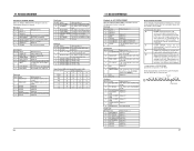
... EXTERNAL 01 VIDEO 10 AUTO 11 IEEE1394 00010000 RC232C 00100000 IEEE1394+RS232C 00110000 RS422A 01000000 IEEE1394+RS422A 01010000 JVC BUS 10000000 JVC BUS+IEEE1394 10010000 JVC BUS+RS232C 10100000 JVC BUS+RS232C+1394 1 0 1 1 0 0 0 0 JVC BUS+RS422A 11000000 JVC BUS+RS422A+1394 1 1 0 1 0 0 0 0 LINE 00 Y/C 01 COMPONENT 10 IEEE1394 ...0 1 000 001 010 011 0 1 39 Transmit the data (3 bytes) corresponding to the menu switch to change the VCR's menu switches. As can confirm the setting with the returned data (D1, D2). (e.g.) Check the No. 108 menu switch...
... EXTERNAL 01 VIDEO 10 AUTO 11 IEEE1394 00010000 RC232C 00100000 IEEE1394+RS232C 00110000 RS422A 01000000 IEEE1394+RS422A 01010000 JVC BUS 10000000 JVC BUS+IEEE1394 10010000 JVC BUS+RS232C 10100000 JVC BUS+RS232C+1394 1 0 1 1 0 0 0 0 JVC BUS+RS422A 11000000 JVC BUS+RS422A+1394 1 1 0 1 0 0 0 0 LINE 00 Y/C 01 COMPONENT 10 IEEE1394 ...0 1 000 001 010 011 0 1 39 Transmit the data (3 bytes) corresponding to the menu switch to change the VCR's menu switches. As can confirm the setting with the returned data (D1, D2). (e.g.) Check the No. 108 menu switch...
45 pg user manual for BR-DV600U/E VTR (1130KB)
Page 22
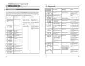
... "1.7 WARNIGN CODES". 12 TROUBLESHOOTING 12-1 Warning indicators If the unit malfunctions during operation, the built-in the LP mode. The VCR's built-in the LP mode is abnormal. On-screen display Counter display Error contents Operation Solution CONDENSATION ON DRUM The [DEW] ...is abnormal. The tape was attempted on again to the [DV IN/OUT] connector. Audio dubbing was recorded with a dedicated head cleaning tape. Operation stops. The fan motor stops. Consult your JVC dealer. Consult your JVC dealer. 40 12 TROUBLESHOOTING On-screen display Counter display Error...
... "1.7 WARNIGN CODES". 12 TROUBLESHOOTING 12-1 Warning indicators If the unit malfunctions during operation, the built-in the LP mode. The VCR's built-in the LP mode is abnormal. On-screen display Counter display Error contents Operation Solution CONDENSATION ON DRUM The [DEW] ...is abnormal. The tape was attempted on again to the [DV IN/OUT] connector. Audio dubbing was recorded with a dedicated head cleaning tape. Operation stops. The fan motor stops. Consult your JVC dealer. Consult your JVC dealer. 40 12 TROUBLESHOOTING On-screen display Counter display Error...
45 pg user manual for BR-DV600U/E VTR (1130KB)
Page 23
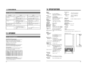
...8 Ω, unbalanced [Time code] 5 Output : 0 ± 3 dBs, low impedance, unbalanced [DV interface] 5 Input/output: IEEE 1394 [Connectors] 5 RS-422 interface : D-sub 9-pin 5 JVC bus connector : DIN 12-pin Accessory AC cable x 1 Option SA-K46U RS-232C interface board Design ... CH-1/3 REC LEVEL VIDEO CASSETTE RECORDER BR-DV600U OPERATE ON/OFF EJECT CH-2/4 MENU ADVANCE PRESET SHIFT SHIFT HOLD SHIFT A. For installation and uninstallation, consult your JVC dealer. 12 TROUBLESHOOTING 12-2 Other problems Symptoms Causes Action The VCR's controls are available. YC video...
...8 Ω, unbalanced [Time code] 5 Output : 0 ± 3 dBs, low impedance, unbalanced [DV interface] 5 Input/output: IEEE 1394 [Connectors] 5 RS-422 interface : D-sub 9-pin 5 JVC bus connector : DIN 12-pin Accessory AC cable x 1 Option SA-K46U RS-232C interface board Design ... CH-1/3 REC LEVEL VIDEO CASSETTE RECORDER BR-DV600U OPERATE ON/OFF EJECT CH-2/4 MENU ADVANCE PRESET SHIFT SHIFT HOLD SHIFT A. For installation and uninstallation, consult your JVC dealer. 12 TROUBLESHOOTING 12-2 Other problems Symptoms Causes Action The VCR's controls are available. YC video...


