User Guide
Page 5
... a list of the product, and product diagrams to update the system. For further information, see http:// support.intel.com/support/motherboards/server/s5000vsa/. This manual is available in the Intel® 5000 Series Chipsets Server Board Family Datasheet. Information about the specific BIOS settings and screens is written for system technicians who are shipped with the Intel® Server Board S5000VSA. Use this chapter for step-by step instructions on how to add and replace components...
... a list of the product, and product diagrams to update the system. For further information, see http:// support.intel.com/support/motherboards/server/s5000vsa/. This manual is available in the Intel® 5000 Series Chipsets Server Board Family Datasheet. Information about the specific BIOS settings and screens is written for system technicians who are shipped with the Intel® Server Board S5000VSA. Use this chapter for step-by step instructions on how to add and replace components...

User Guide
Page 6
...; Six SATA cables, installed in the server system • SPGIO cable, installed in the server system • Front panel cable, installed in the server system • USB Y cable for floppy drive and front panel cable, installed in the server system • I/O shield, installed in the server system • Quick Reference Label, installed inside the server system top cover • Front panel sub-bezel assembly, installed in the server system • CD-ROM cable, in the server system product box • Attention document, in the server system product box • Quick Start User's Guide...
...; Six SATA cables, installed in the server system • SPGIO cable, installed in the server system • Front panel cable, installed in the server system • USB Y cable for floppy drive and front panel cable, installed in the server system • I/O shield, installed in the server system • Quick Reference Label, installed inside the server system top cover • Front panel sub-bezel assembly, installed in the server system • CD-ROM cable, in the server system product box • Attention document, in the server system product box • Quick Start User's Guide...

User Guide
Page 7
... SAS cables, installed in the server system • I2C cable, installed in the server system • Front panel cable, installed in the server system • USB Y cable for floppy drive and front panel cable, installed in the server system • I/O shield, installed in the server system • Quick Reference Label, installed inside the server system top cover • Front panel sub-bezel assembly, installed in the server system • CD-ROM cable, in the server system product box • Attention document, in the server system product box • Quick Start User's Guide...
... SAS cables, installed in the server system • I2C cable, installed in the server system • Front panel cable, installed in the server system • USB Y cable for floppy drive and front panel cable, installed in the server system • I/O shield, installed in the server system • Quick Reference Label, installed inside the server system top cover • Front panel sub-bezel assembly, installed in the server system • CD-ROM cable, in the server system product box • Attention document, in the server system product box • Quick Start User's Guide...

User Guide
Page 8
...fan, installed in the server system • CPU air duct, installed in the server system • Standard control panel, installed in the server system • Slimline USB floppy drive, installed in the server system • Front panel cable, installed in the server system • USB Y cable for floppy drive and front panel cable, installed in the server system • I/O shield, installed in the server system • Quick Reference Label, installed inside the server system top cover • Front panel sub-bezel assembly, installed in the server system • CD-ROM cable, in the server...
...fan, installed in the server system • CPU air duct, installed in the server system • Standard control panel, installed in the server system • Slimline USB floppy drive, installed in the server system • Front panel cable, installed in the server system • USB Y cable for floppy drive and front panel cable, installed in the server system • I/O shield, installed in the server system • Quick Reference Label, installed inside the server system top cover • Front panel sub-bezel assembly, installed in the server system • CD-ROM cable, in the server...
User Guide
Page 14
... the Server Board 51 Replacing the Backup Battery 52 Replacing the Redundant Power Supply (SR2520SAX/SR2520SAXS and SR2520SAXR/ SR2520SAXSR) ...54 Replacing the Fixed Power Supply (SR2520SAF/SR2520SAFR 55 Replacing the Front Panel Board 57 Replacing a System Fan ...60 Installing and Removing the Rack Handles 62 Installing the Rack Handles 62 Removing the Rack Handles 63 Chapter 4: Server Utilities 65 Using the BIOS Setup Utility 65 Starting Setup ...65 If You Cannot Access Setup 65 Setup Menus ...65 Upgrading the BIOS ...67 xiv Intel® Server System SR2520SA User's Guide
... the Server Board 51 Replacing the Backup Battery 52 Replacing the Redundant Power Supply (SR2520SAX/SR2520SAXS and SR2520SAXR/ SR2520SAXSR) ...54 Replacing the Fixed Power Supply (SR2520SAF/SR2520SAFR 55 Replacing the Front Panel Board 57 Replacing a System Fan ...60 Installing and Removing the Rack Handles 62 Installing the Rack Handles 62 Removing the Rack Handles 63 Chapter 4: Server Utilities 65 Using the BIOS Setup Utility 65 Starting Setup ...65 If You Cannot Access Setup 65 Setup Menus ...65 Upgrading the BIOS ...67 xiv Intel® Server System SR2520SA User's Guide

User Guide
Page 16
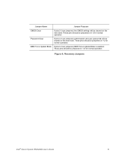
... Light Does Not Light 102 CD-ROM Drive or DVD-ROM Drive Activity Light Does Not Light 102 Cannot Connect to a Server 102 Problems with Network 103 System Boots when Installing PCI Card 104 Problems with Newly Installed Application Software 104 Problems with Application Software that Ran Correctly Earlier 104 Devices are not Recognized under Device Manager (Microsoft* Windows* Operating System) ...105 Hard Drive(s) are not Recognized 105 Bootable CD-ROM Disk Is Not Detected 105 LED Information ...106 BIOS POST Beep Codes 106 Appendix G: Installation/Assembly Safety Instructions...
... Light Does Not Light 102 CD-ROM Drive or DVD-ROM Drive Activity Light Does Not Light 102 Cannot Connect to a Server 102 Problems with Network 103 System Boots when Installing PCI Card 104 Problems with Newly Installed Application Software 104 Problems with Application Software that Ran Correctly Earlier 104 Devices are not Recognized under Device Manager (Microsoft* Windows* Operating System) ...105 Hard Drive(s) are not Recognized 105 Bootable CD-ROM Disk Is Not Detected 105 LED Information ...106 BIOS POST Beep Codes 106 Appendix G: Installation/Assembly Safety Instructions...
User Guide
Page 19
... Figure 26. Installing Fixed Hard Drive(s) into the Drive Bracket 45 Figure 33. List of Figures Figure 1. BIOS Select Jumper 10 Figure 6. Hot-Swap Backplane 14 Figure 11. Standard Control Panel 17 Figure 12. Removing the Processor Air Duct 29 Figure 20. Removing Hot-swap Disk Carrier from Drive Carrier (SR2520SAX/SR2520SAXS and SR2520SAXR/SR2520SAXSR 39 Figure 28. Removing Optical Drive Knockout 45 Intel® Server System SR2520SA User's Guide xix Light Guided Diagnostic LEDs (SR2520SAX/SR2520SAXS...
... Figure 26. Installing Fixed Hard Drive(s) into the Drive Bracket 45 Figure 33. List of Figures Figure 1. BIOS Select Jumper 10 Figure 6. Hot-Swap Backplane 14 Figure 11. Standard Control Panel 17 Figure 12. Removing the Processor Air Duct 29 Figure 20. Removing Hot-swap Disk Carrier from Drive Carrier (SR2520SAX/SR2520SAXS and SR2520SAXR/SR2520SAXSR 39 Figure 28. Removing Optical Drive Knockout 45 Intel® Server System SR2520SA User's Guide xix Light Guided Diagnostic LEDs (SR2520SAX/SR2520SAXS...

User Guide
Page 27
... ATA-133 connector • SSI-compliant 34-pin, high-density 100-pin, and alternate 50- Optional RAID 5 support requires an AXXRAKSW5 RAID key. • SR2520SAXS/SR2520SAXSR: Four SAS and two SATA connectors with embedded RAID 0/1/10 support for IDE optical drive • PCI riser card bracket • Standard control panel With standard control panel: • NIC1 Activity • NIC2 Activity • Power / Sleep • System Status • System Identification • Hard Drive Activity Intel® Server System SR2520SA User's Guide 5 Table...
... ATA-133 connector • SSI-compliant 34-pin, high-density 100-pin, and alternate 50- Optional RAID 5 support requires an AXXRAKSW5 RAID key. • SR2520SAXS/SR2520SAXSR: Four SAS and two SATA connectors with embedded RAID 0/1/10 support for IDE optical drive • PCI riser card bracket • Standard control panel With standard control panel: • NIC1 Activity • NIC2 Activity • Power / Sleep • System Status • System Identification • Hard Drive Activity Intel® Server System SR2520SA User's Guide 5 Table...
User Guide
Page 33
If pins 2-3 are jumpered, BMC Force Update Mode is enabled. Figure 6. If pins 2-3 are jumpered, administrator and user passwords will be jumpered on 1-2 for normal operation. Recovery Jumpers Intel® Server System SR2520SA User's Guide 11 These pins should be cleared on the next reset. These pins should be jumpered on 1-2 for normal operation. Jumper Name Jumper Purpose CMOS Clear Password Clear BMC Force Update Mode If pins 2-3 are jumpered, the CMOS settings will be jumpered on 1-2 for normal operation. These pins should be cleared on the next reset.
If pins 2-3 are jumpered, BMC Force Update Mode is enabled. Figure 6. If pins 2-3 are jumpered, administrator and user passwords will be jumpered on 1-2 for normal operation. Recovery Jumpers Intel® Server System SR2520SA User's Guide 11 These pins should be cleared on the next reset. These pins should be jumpered on 1-2 for normal operation. Jumper Name Jumper Purpose CMOS Clear Password Clear BMC Force Update Mode If pins 2-3 are jumpered, the CMOS settings will be jumpered on 1-2 for normal operation. These pins should be cleared on the next reset.
User Guide
Page 38
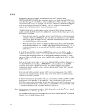
... black ports on RAID configuration through the BIOS Setup utility, see the RAID Software Guide. 16 Intel® Server System SR2520SA User's Guide If RAID 5 is not available unless enabled in the BIOS Setup utility, but they share the Intel® RAID Web Console 2 management utility. The BIOS Setup utility includes options on the Advanced | Mass Storage setup page to enable RAID 5, see the documentation that is enabled, the four blue ports on the server board continue to function as either or both SAS and SATA hard disk drives...
... black ports on RAID configuration through the BIOS Setup utility, see the RAID Software Guide. 16 Intel® Server System SR2520SA User's Guide If RAID 5 is not available unless enabled in the BIOS Setup utility, but they share the Intel® RAID Web Console 2 management utility. The BIOS Setup utility includes options on the Advanced | Mass Storage setup page to enable RAID 5, see the documentation that is enabled, the four blue ports on the server board continue to function as either or both SAS and SATA hard disk drives...

User Guide
Page 41
.... Instructions for an Internet link to run at a maximum ambient temperature of 45C. Intel® Server System SR2520SA User's Guide 19 Note: Drives can be specified to a list of power each. In other words, install the first system in the second position from the bottom of the rack to 17 watts of supported hardware. Note: The Intel® Server System SR2520SA does not support all SAS or Serial ATA (SATA) hard drives. When installing...
.... Instructions for an Internet link to run at a maximum ambient temperature of 45C. Intel® Server System SR2520SA User's Guide 19 Note: Drives can be specified to a list of power each. In other words, install the first system in the second position from the bottom of the rack to 17 watts of supported hardware. Note: The Intel® Server System SR2520SA does not support all SAS or Serial ATA (SATA) hard drives. When installing...

User Guide
Page 66
... Optical Drive 1. Installing or Removing the Optical Drive Cautions: The optical drive is installed. Removing Drive Bracket from the system (see "Replacing the Front Panel Board". 6. See "Safety Information". 2. Remove the server system cover. A B AF001825 Figure 31. Power down the server and unplug all peripheral devices connected to the server system (see letter "A" in the figure below), and remove the bracket from the Server System 44 Intel® Server System SR2520SA User's Guide Remove the front bezel if it is NOT hot swappable. For instructions...
... Optical Drive 1. Installing or Removing the Optical Drive Cautions: The optical drive is installed. Removing Drive Bracket from the system (see "Replacing the Front Panel Board". 6. See "Safety Information". 2. Remove the server system cover. A B AF001825 Figure 31. Power down the server and unplug all peripheral devices connected to the server system (see letter "A" in the figure below), and remove the bracket from the Server System 44 Intel® Server System SR2520SA User's Guide Remove the front bezel if it is NOT hot swappable. For instructions...

User Guide
Page 77
... of the fans that is not hot-swappable. Installing Power Supply Module into the server. To replace the power supply, use the following instructions. 1. Before removing or replacing the power supply, you must first take the server out of service, turn off the system by removing the two screws holding it fails. Intel® Server System SR2520SA User's Guide 55 A AF001456 Figure 43. See "Safety Information". 2. Replacing the Fixed Power Supply (SR2520SAF/ SR2520SAFR) Caution: The power supply is integrated...
... of the fans that is not hot-swappable. Installing Power Supply Module into the server. To replace the power supply, use the following instructions. 1. Before removing or replacing the power supply, you must first take the server out of service, turn off the system by removing the two screws holding it fails. Intel® Server System SR2520SA User's Guide 55 A AF001456 Figure 43. See "Safety Information". 2. Replacing the Fixed Power Supply (SR2520SAF/ SR2520SAFR) Caution: The power supply is integrated...
User Guide
Page 90
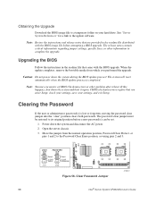
...a BIOS upgrade. CMOS checksum errors require that came with the BIOS image file before a new password(s) can be restored to complete the upgrade. Clear Password Jumper AF000187 68 Intel® Server System SR2520SA User's Guide See "Server System References" for a link to the Password Clear Erase position, covering pins 2 and 3. When the update completes, remove the bootable media from the normal operation position, Password Clear Protect, at pins 1 and 2 to the update software. Obtaining the Upgrade Download the BIOS image file to a temporary folder on your settings, and...
...a BIOS upgrade. CMOS checksum errors require that came with the BIOS image file before a new password(s) can be restored to complete the upgrade. Clear Password Jumper AF000187 68 Intel® Server System SR2520SA User's Guide See "Server System References" for a link to the Password Clear Erase position, covering pins 2 and 3. When the update completes, remove the bootable media from the normal operation position, Password Clear Protect, at pins 1 and 2 to the update software. Obtaining the Upgrade Download the BIOS image file to a temporary folder on your settings, and...
User Guide
Page 120
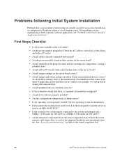
... add-in boards sharing the same interrupt. • Are all device drivers properly installed? • Are the configuration settings made in boards and peripheral devices correct? Hardware failure is it properly formatted or configured? • Are all peripheral devices installed correctly? • If the system has a hard disk drive, is a less frequent cause. To check these settings, refer to the tested component lists. 98 Intel® Server System SR2520SA User's Guide Check the AC cable(s) on the server board...
... add-in boards sharing the same interrupt. • Are all device drivers properly installed? • Are the configuration settings made in boards and peripheral devices correct? Hardware failure is it properly formatted or configured? • Are all peripheral devices installed correctly? • If the system has a hard disk drive, is a less frequent cause. To check these settings, refer to the tested component lists. 98 Intel® Server System SR2520SA User's Guide Check the AC cable(s) on the server board...

User Guide
Page 121
... video display monitor and keyboard are correctly connected to the system and/or the peripheral devices. 1. Set its source. If the power LED does not light, see "Drive Activity Light Does Not Light". If not, see "Power Light Does Not Light". Make sure the system power cord is no CD-ROM / DVD disk in the system. If the operating system normally loads from the system, turn off the system and all external peripheral devices. Verifying Proper Operation of Key System Lights As POST determines the system configuration...
... video display monitor and keyboard are correctly connected to the system and/or the peripheral devices. 1. Set its source. If the power LED does not light, see "Drive Activity Light Does Not Light". If not, see "Power Light Does Not Light". Make sure the system power cord is no CD-ROM / DVD disk in the system. If the operating system normally loads from the system, turn off the system and all external peripheral devices. Verifying Proper Operation of Key System Lights As POST determines the system configuration...
User Guide
Page 125
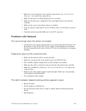
... your PCI card(s) for information on changing interrupts. Diagnostics pass but the connection fails • Make sure the network cable is securely attached. • Make sure you specify the correct frame type in your NET.CFG file. • The controller stopped working without a hub), you are not shared with Network The server hangs when the drivers are using the correct and the current drivers. Intel® Server System SR2520SA User's Guide 103 Make...
... your PCI card(s) for information on changing interrupts. Diagnostics pass but the connection fails • Make sure the network cable is securely attached. • Make sure you specify the correct frame type in your NET.CFG file. • The controller stopped working without a hub), you are not shared with Network The server hangs when the drivers are using the correct and the current drivers. Intel® Server System SR2520SA User's Guide 103 Make...
User Guide
Page 126
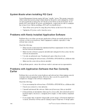
... the system. Make sure all necessary files are installed. • If the problems are running correctly sometimes indicate equipment failure. Symptoms of the system. • Unplug the AC power cord(s) from a CD-ROM or DVD-ROM, try a different disk. • Make sure the correct device drivers installed. However, they can also be a loose cable, dirt in , a signal may be caused by using the power button on the front panel. System Boots when Installing PCI Card System Management features...
... the system. Make sure all necessary files are installed. • If the problems are running correctly sometimes indicate equipment failure. Symptoms of the system. • Unplug the AC power cord(s) from a CD-ROM or DVD-ROM, try a different disk. • Make sure the correct device drivers installed. However, they can also be a loose cable, dirt in , a signal may be caused by using the power button on the front panel. System Boots when Installing PCI Card System Management features...

User Guide
Page 127
... video display, unexpected system reboots, and the system not responding to the current drivers and chipset files. See your drives. • If using a RAID configuration with SCSI or SATA drives, make sure the RAID card is installed correctly. See "Server System References" for details on the SCSI bus. Hard Drive(s) are not Recognized under Device Manager (Microsoft* Windows* Operating System) The Microsoft* Windows* operating systems do not include all of the above symptoms that is plugged into the power supply. • Make...
... video display, unexpected system reboots, and the system not responding to the current drivers and chipset files. See your drives. • If using a RAID configuration with SCSI or SATA drives, make sure the RAID card is installed correctly. See "Server System References" for details on the SCSI bus. Hard Drive(s) are not Recognized under Device Manager (Microsoft* Windows* Operating System) The Microsoft* Windows* operating systems do not include all of the above symptoms that is plugged into the power supply. • Make...
User Guide
Page 128
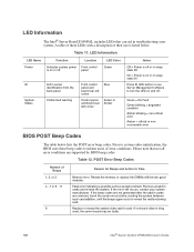
... board rear left corner Control panel and board rear left corner Blue Green or Amber Notes Off = Power is off or in sleep state S5 On = Power is bing used, the server board may be faulty. 106 Intel® Server System SR2520SA User's Guide If the beep codes are not generated after the add-in cards are supported by BIOS beep codes. Prior to system video initialization, the BIOS uses these LEDs with known good modules. Fatal error indicating a possible serious system problem. Remove...
... board rear left corner Control panel and board rear left corner Blue Green or Amber Notes Off = Power is off or in sleep state S5 On = Power is bing used, the server board may be faulty. 106 Intel® Server System SR2520SA User's Guide If the beep codes are not generated after the add-in cards are supported by BIOS beep codes. Prior to system video initialization, the BIOS uses these LEDs with known good modules. Fatal error indicating a possible serious system problem. Remove...


