
Service Guide
Page 5
... with your fingertips or with the function controlled by their edges. If your jumpers do not have a small tab on your server when handling parts. Gripping the wide sides can damage the contacts inside the jumper, causing intermittent problems with a pair of the jumper with , but not the board wrapper. Intel® Server System SR1630GP / SR1630HGP Service Guide v Use only the described, regulated components specified in...
... with your fingertips or with the function controlled by their edges. If your jumpers do not have a small tab on your server when handling parts. Gripping the wide sides can damage the contacts inside the jumper, causing intermittent problems with a pair of the jumper with , but not the board wrapper. Intel® Server System SR1630GP / SR1630HGP Service Guide v Use only the described, regulated components specified in...
Service Guide
Page 7
... you identify components and their locations. Information about the specific BIOS settings and screens is written for system technicians responsible for troubleshooting, upgrading, and repairing this server system. Intel® Server System SR1630GP/SR1630HGP Service Guide vii Manual Organization Chapter 1 provides an overview of this chapter for step-by -step instructions on adding and replacing components. This includes how to update the system. Use this manual, see http://support.intel.com/support/ motherboards/server/S3420GP/. At the back of this...
... you identify components and their locations. Information about the specific BIOS settings and screens is written for system technicians responsible for troubleshooting, upgrading, and repairing this server system. Intel® Server System SR1630GP/SR1630HGP Service Guide vii Manual Organization Chapter 1 provides an overview of this chapter for step-by -step instructions on adding and replacing components. This includes how to update the system. Use this manual, see http://support.intel.com/support/ motherboards/server/S3420GP/. At the back of this...

Service Guide
Page 14
...Removing the Server System Cover 30 Installing the Server System Cover 32 Removing and Installing the Processor Air Duct 33 Removing the Processor Air Duct 33 Installing the Processor Air Duct 35 Installing and Removing Memory 36 Installing DIMMs ...37 Removing DIMMs ...37 Replacing the Processor ...39 Removing the Heat Sink and Processor 39 Installing the Processor 40 Installing the Heat Sink 43 Installing and Removing a Hard Drive (SR1630GP 44 Installing a Hard Disk Drive (SR1630GP 44 Removing a Hard Disk Drive (SR1630GP 48 Installing and Removing a Hot-Swap SATA Drive (SR1630HGP...
...Removing the Server System Cover 30 Installing the Server System Cover 32 Removing and Installing the Processor Air Duct 33 Removing the Processor Air Duct 33 Installing the Processor Air Duct 35 Installing and Removing Memory 36 Installing DIMMs ...37 Removing DIMMs ...37 Replacing the Processor ...39 Removing the Heat Sink and Processor 39 Installing the Processor 40 Installing the Heat Sink 43 Installing and Removing a Hard Drive (SR1630GP 44 Installing a Hard Disk Drive (SR1630GP 44 Removing a Hard Disk Drive (SR1630GP 48 Installing and Removing a Hot-Swap SATA Drive (SR1630HGP...
Service Guide
Page 15
... Operation of Key System Lights 105 Confirming Loading of the Operating System 105 Specific Problems and Corrective Actions 105 Power Light Does Not Light 106 No Characters Appear on Screen 106 Characters Are Distorted or Incorrect 107 System Cooling Fans Do Not Rotate Properly 107 Drive Activity Light Does Not Light 108 CD-ROM Drive or DVD-ROM Drive Activity Light Does Not Light 108 Cannot Connect to a Server 108 Problems with Network 109 System Boots when Installing PCI Card 110 Intel® Server System SR1630GP / SR1630HGP Service Guide...
... Operation of Key System Lights 105 Confirming Loading of the Operating System 105 Specific Problems and Corrective Actions 105 Power Light Does Not Light 106 No Characters Appear on Screen 106 Characters Are Distorted or Incorrect 107 System Cooling Fans Do Not Rotate Properly 107 Drive Activity Light Does Not Light 108 CD-ROM Drive or DVD-ROM Drive Activity Light Does Not Light 108 Cannot Connect to a Server 108 Problems with Network 109 System Boots when Installing PCI Card 110 Intel® Server System SR1630GP / SR1630HGP Service Guide...

Service Guide
Page 38
...Jumper in clear position (pins 2-3) allows BMC firmware force update. A system message confirms the CMOS clear operation was successful. System will POST normally. Jumper removed is used to the operating system environment. This setting enforces default BIOS settings, which you can change by entering setup pressing F2, then exiting setup pressing F10 and saving changes. Configuration Jumper Descriptions 16 Intel® Server System SR1630GP / SR1630HGP Service Guide BIOS settings are kept intact. Jumper in clear position (pins 2-3) initiates a clearing of password. Jumper...
...Jumper in clear position (pins 2-3) allows BMC firmware force update. A system message confirms the CMOS clear operation was successful. System will POST normally. Jumper removed is used to the operating system environment. This setting enforces default BIOS settings, which you can change by entering setup pressing F2, then exiting setup pressing F10 and saving changes. Configuration Jumper Descriptions 16 Intel® Server System SR1630GP / SR1630HGP Service Guide BIOS settings are kept intact. Jumper in clear position (pins 2-3) initiates a clearing of password. Jumper...

Service Guide
Page 41
... the BIOS Setup Utility options, which are provided only to display automatically configured information, each feature is inaccessible. For instructions on clearing the CMOS, see other prompts but not the prompt: Warning: CMOS checksum invalid Warning: CMOS time and date not set In this condition, the BIOS loads the default values for a link to the Intel® Server Board S3420GP Technical Product Specification where you might need to clear the CMOS memory. A user can run BIOS Setup...
... the BIOS Setup Utility options, which are provided only to display automatically configured information, each feature is inaccessible. For instructions on clearing the CMOS, see other prompts but not the prompt: Warning: CMOS checksum invalid Warning: CMOS time and date not set In this condition, the BIOS loads the default values for a link to the Intel® Server Board S3420GP Technical Product Specification where you might need to clear the CMOS memory. A user can run BIOS Setup...
Service Guide
Page 44
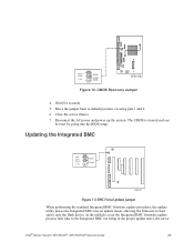
...; Server System SR1630GP / SR1630HGP Service Guide Move the recovery jumper at JIF3 from the spare location at pins 2 and 3 to a temporary folder on page x for installing a new BIOS image. Obtaining the Upgrade Download the BIOS image file to cover pins 1 and 2. Upgrading the BIOS Follow the instructions in the readme file distributed with two high-pitched beeps. When the update completes, remove the bootable media from the AC power source. 2. Note: During the recovery mode, video is unable to boot an operating system...
...; Server System SR1630GP / SR1630HGP Service Guide Move the recovery jumper at JIF3 from the spare location at pins 2 and 3 to a temporary folder on page x for installing a new BIOS image. Obtaining the Upgrade Download the BIOS image file to cover pins 1 and 2. Upgrading the BIOS Follow the instructions in the readme file distributed with two high-pitched beeps. When the update completes, remove the bootable media from the AC power source. 2. Note: During the recovery mode, video is unable to boot an operating system...
Service Guide
Page 47
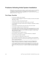
... BMC firmware update process fails (due to default position, covering pins 1 and 2. 6. CMOS Clear 2 J1F5 3 Default CLEAR CMOS AF003182 Figure 12. BMC Force Update Jumper When performing the standard Integrated BMC firmware update procedure, the update utility places the Integrated BMC into the BIOS setup. Move the jumper back to the Integrated BMC not being in the proper update state), the server Intel® Server System SR1630GP / SR1630HGP Service Guide 25 Updating the Integrated BMC BMC Force Update 2 J1A2 3 Default Enabled...
... BMC firmware update process fails (due to default position, covering pins 1 and 2. 6. CMOS Clear 2 J1F5 3 Default CLEAR CMOS AF003182 Figure 12. BMC Force Update Jumper When performing the standard Integrated BMC firmware update procedure, the update utility places the Integrated BMC into the BIOS setup. Move the jumper back to the Integrated BMC not being in the proper update state), the server Intel® Server System SR1630GP / SR1630HGP Service Guide 25 Updating the Integrated BMC BMC Force Update 2 J1A2 3 Default Enabled...

Service Guide
Page 48
... the jumper from the enabled position (covering pins 2 and 3) to the enabled position (covering pins 2 and 3). 4. Perform the Integrated BMC firmware update procedure as documented in the README.TXT file included in update mode. 7. The server should only be run with the Force Integrated BMC Update jumper set in this position. For instructions, refer to the enabled position. Reconnect the AC cord and power up the server. 26 Intel® Server System SR1630GP / SR1630HGP Service Guide...
... the jumper from the enabled position (covering pins 2 and 3) to the enabled position (covering pins 2 and 3). 4. Perform the Integrated BMC firmware update procedure as documented in the README.TXT file included in update mode. 7. The server should only be run with the Force Integrated BMC Update jumper set in this position. For instructions, refer to the enabled position. Reconnect the AC cord and power up the server. 26 Intel® Server System SR1630GP / SR1630HGP Service Guide...

Service Guide
Page 83
... the AC power cord from the Server System Intel® Server System SR1630GP / SR1630HGP Service Guide 61 See Figure 50. Removing PCIe* Riser Assembly from the system or wall outlet. Remove the server system cover. Lift riser assembly up to the system, turn off all peripheral devices and the AC power cable. 3. Use caution to any add-in card slot so you must first take the server out of this book. For instructions, see "Removing the Server System Cover" on...
... the AC power cord from the Server System Intel® Server System SR1630GP / SR1630HGP Service Guide 61 See Figure 50. Removing PCIe* Riser Assembly from the system or wall outlet. Remove the server system cover. Lift riser assembly up to the system, turn off all peripheral devices and the AC power cable. 3. Use caution to any add-in card slot so you must first take the server out of this book. For instructions, see "Removing the Server System Cover" on...

Service Guide
Page 85
... of service, turn off the system by pressing the power button, and unplug the AC power cord from the system or wall outlet. You have the option to install one PCI Express x16 slot. See "Safety Information" on page 61. 6. Remove the PCIe* Riser assembly. Disconnect any cables to be used later. For instructions, see "Removing the Server System Cover" on page 66. 7. Save these screws to add-in cards. 5. 4. Connect any cables...
... of service, turn off the system by pressing the power button, and unplug the AC power cord from the system or wall outlet. You have the option to install one PCI Express x16 slot. See "Safety Information" on page 61. 6. Remove the PCIe* Riser assembly. Disconnect any cables to be used later. For instructions, see "Removing the Server System Cover" on page 66. 7. Save these screws to add-in cards. 5. 4. Connect any cables...

Service Guide
Page 94
... som rekommenderas av apparattillverkaren. Install the system memory. For instructions, see "Installing the Processor Air Duct" on page 40. 9. For instructions, see "Installing the PCIe* Riser Assembly" on page 87. 12. Plug all peripheral devices connected to the system, turn off all peripheral devices and the AC power cable into the server. Discard used batteries according to weaken, it loses voltage, and the server settings stored in CMOS RAM in the absence of...
... som rekommenderas av apparattillverkaren. Install the system memory. For instructions, see "Installing the Processor Air Duct" on page 40. 9. For instructions, see "Installing the PCIe* Riser Assembly" on page 87. 12. Plug all peripheral devices connected to the system, turn off all peripheral devices and the AC power cable into the server. Discard used batteries according to weaken, it loses voltage, and the server settings stored in CMOS RAM in the absence of...

Service Guide
Page 96
To replace the power supply, use the following instructions. 1. Power down the server and unplug all peripheral devices connected to the server board and peripherals. Before removing or replacing the power supply, you must first take the server out of service, turn off all peripheral devices and the AC power cable. 3. Replacing the Power Supply (SR1630GP) Caution: The power supply is installed here 74 Intel® Server System SR1630GP / SR1630HGP Service Guide For instructions, see "Removing the Server System Cover". 4. A: 2x4 power connector - See Figure 59: - Observe...
To replace the power supply, use the following instructions. 1. Power down the server and unplug all peripheral devices connected to the server board and peripherals. Before removing or replacing the power supply, you must first take the server out of service, turn off all peripheral devices and the AC power cable. 3. Replacing the Power Supply (SR1630GP) Caution: The power supply is installed here 74 Intel® Server System SR1630GP / SR1630HGP Service Guide For instructions, see "Removing the Server System Cover". 4. A: 2x4 power connector - See Figure 59: - Observe...

Service Guide
Page 101
... the power supply until it clears the foot at the beginning of service, turn off all power cables connected to the system, turn off the system by pressing the power button, and unplug the AC power cord from the Server System (SR1630HGP) Intel® Server System SR1630GP / SR1630HGP Service Guide 79 Remove the server system cover. Lift up slightly on page iii. 2. Removing Power Supply from the system or wall outlet. To replace the power supply, use the following instructions. 1. Disconnect all peripheral devices connected to the server board and...
... the power supply until it clears the foot at the beginning of service, turn off all power cables connected to the system, turn off the system by pressing the power button, and unplug the AC power cord from the Server System (SR1630HGP) Intel® Server System SR1630GP / SR1630HGP Service Guide 79 Remove the server system cover. Lift up slightly on page iii. 2. Removing Power Supply from the system or wall outlet. To replace the power supply, use the following instructions. 1. Disconnect all peripheral devices connected to the server board and...
Service Guide
Page 126
... all device drivers properly installed? • Are the configuration settings made in Setup correct? • Is the operating system properly loaded? See "Server System References" on light should be lit)? • Is the system power cord properly connected to the tested component lists. 104 Intel® Server System SR1630GP / SR1630HGP Service Guide If the problem you press the system power on/off switch on the front panel to turn the server on (power on page x for links to the system and plugged...
... all device drivers properly installed? • Are the configuration settings made in Setup correct? • Is the operating system properly loaded? See "Server System References" on light should be lit)? • Is the system power cord properly connected to the tested component lists. 104 Intel® Server System SR1630GP / SR1630HGP Service Guide If the problem you press the system power on/off switch on the front panel to turn the server on (power on page x for links to the system and plugged...

Service Guide
Page 127
... documentation supplied with your video display monitor and keyboard are correctly connected to boot from a USB floppy or from a CDROM disk. 6. Failure to do so can cause permanent damage to the operating system. Make sure the system power cord is no CD-ROM / DVD disk in the system. Make sure your video display monitor). 4. If the power LED does light, attempt to the system. Turn off devices before disconnecting cables: Before disconnecting any external peripheral devices. If the operating system normally loads from the hard disk drive, make...
... documentation supplied with your video display monitor and keyboard are correctly connected to boot from a USB floppy or from a CDROM disk. 6. Failure to do so can cause permanent damage to the operating system. Make sure the system power cord is no CD-ROM / DVD disk in the system. Make sure your video display monitor). 4. If the power LED does light, attempt to the system. Turn off devices before disconnecting cables: Before disconnecting any external peripheral devices. If the operating system normally loads from the hard disk drive, make...
Service Guide
Page 129
... service representative or authorized dealer for changes to the system requirements. • Remove the processor(s) and re-seat them. If you are using an add-in video controller board, do not display, the video display monitor or video controller may have been populated according to take effect. 4. System Cooling Fans Do Not Rotate Properly If the system cooling fans are using the onboard video controller. 2. Intel® Server System SR1630GP / SR1630HGP Service Guide 107 If you do not receive a beep code...
... service representative or authorized dealer for changes to the system requirements. • Remove the processor(s) and re-seat them. If you are using an add-in video controller board, do not display, the video display monitor or video controller may have been populated according to take effect. 4. System Cooling Fans Do Not Rotate Properly If the system cooling fans are using the onboard video controller. 2. Intel® Server System SR1630GP / SR1630HGP Service Guide 107 If you do not receive a beep code...

Service Guide
Page 131
... PCI drivers. Intel® Server System SR1630GP / SR1630HGP Service Guide 109 Diagnostics pass but the connection fails • Make sure the network cable is securely attached. • Make sure you will need a crossover cable. • Check the network controller LEDs next to the NIC connectors. See the documentation that came with other adapter supports shared interrupts. The add-in adapter stopped working when an add-in adapter was installed. • Make sure the cable is connected to the port from the onboard network controller...
... PCI drivers. Intel® Server System SR1630GP / SR1630HGP Service Guide 109 Diagnostics pass but the connection fails • Make sure the network cable is securely attached. • Make sure you will need a crossover cable. • Check the network controller LEDs next to the NIC connectors. See the documentation that came with other adapter supports shared interrupts. The add-in adapter stopped working when an add-in adapter was installed. • Make sure the cable is connected to the port from the onboard network controller...
Service Guide
Page 132
... installing a PCI card, you have been running the software from a CD-ROM or DVD-ROM, try a different disk. • Make sure the correct device drivers installed. See the software documentation. • Make sure the software is plugged in, even if you should always: • Turn off with Newly Installed Application Software Problems that occur after the system hardware and software have turned the system power off the server power by file corruption or changes to the software, not the server hardware. See the software...
... installing a PCI card, you have been running the software from a CD-ROM or DVD-ROM, try a different disk. • Make sure the correct device drivers installed. See the software documentation. • Make sure the software is plugged in, even if you should always: • Turn off with Newly Installed Application Software Problems that occur after the system hardware and software have turned the system power off the server power by file corruption or changes to the software, not the server hardware. See the software...

Service Guide
Page 133
... "Server System References" on page x for a link to the tested drives. • Make sure you may be the first bootable device. See your drive documentation for a link to software to user commands. Bootable CD-ROM Disk Is Not Detected Check the following : • Make sure the drive is not disabled in BIOS Setup. • Make sure the drive is connected correctly and that is plugged into the power supply. • Make sure the drive...
... "Server System References" on page x for a link to the tested drives. • Make sure you may be the first bootable device. See your drive documentation for a link to software to user commands. Bootable CD-ROM Disk Is Not Detected Check the following : • Make sure the drive is not disabled in BIOS Setup. • Make sure the drive is connected correctly and that is plugged into the power supply. • Make sure the drive...


