Service Guide
Page 3
.... This includes a list of this manual provides technical specifications, regulatory information, "getting help you for troubleshooting, upgrading, and repairing this server system. Intel® Server System SR1625UR Service Guide iii This manual is written for system technicians who are responsible for purchasing and using the utilities that are shipped with the board or that provide additional details on adding and replacing components. Chapter 3 provides instructions on the Intel® Server System SR1625UR, and the location where they can...
.... This includes a list of this manual provides technical specifications, regulatory information, "getting help you for troubleshooting, upgrading, and repairing this server system. Intel® Server System SR1625UR Service Guide iii This manual is written for system technicians who are responsible for purchasing and using the utilities that are shipped with the board or that provide additional details on adding and replacing components. Chapter 3 provides instructions on the Intel® Server System SR1625UR, and the location where they can...

Service Guide
Page 7
... problems with the function controlled by wearing an antistatic wrist strap attached to chassis ground any other tool you use to remove a jumper, or you may be extremely sensitive to the assembly instructions in this guide or any unpainted metal surface on a grounded, static free surface. Intel® Server System SR1625UR Service Guide vii Use of other products/ components will void the UL listing and other parts. Turn...
... problems with the function controlled by wearing an antistatic wrist strap attached to chassis ground any other tool you use to remove a jumper, or you may be extremely sensitive to the assembly instructions in this guide or any unpainted metal surface on a grounded, static free surface. Intel® Server System SR1625UR Service Guide vii Use of other products/ components will void the UL listing and other parts. Turn...

Service Guide
Page 9
...; Light-Guided Diagnostics 10 Server Board Components 14 Configuration Jumpers 16 Front of Server System ...18 Peripheral Devices ...18 Control Panel ...19 Bezels ...23 Rear of Server System ...24 Back Panel Connectors 25 SAS/SATA Midplanes ...27 Passive Midplane ...27 Active Midplane ...28 Hot-swap SAS/SATA Backplane 29 RAID Support ...30 Advanced Management Options 30 Intel® Remote Management Module 3 30 Rack Mount Options ...31 Chapter 3: Hardware Installations and Upgrades 33 Before You Begin ...33 Tools and Supplies Needed 33 Intel® Server System SR1625UR Service Guide...
...; Light-Guided Diagnostics 10 Server Board Components 14 Configuration Jumpers 16 Front of Server System ...18 Peripheral Devices ...18 Control Panel ...19 Bezels ...23 Rear of Server System ...24 Back Panel Connectors 25 SAS/SATA Midplanes ...27 Passive Midplane ...27 Active Midplane ...28 Hot-swap SAS/SATA Backplane 29 RAID Support ...30 Advanced Management Options 30 Intel® Remote Management Module 3 30 Rack Mount Options ...31 Chapter 3: Hardware Installations and Upgrades 33 Before You Begin ...33 Tools and Supplies Needed 33 Intel® Server System SR1625UR Service Guide...

Service Guide
Page 10
... 55 Removing the Heatsink 57 Removing the Processor 58 Installing and Removing a Hot-swap Hard Drive 59 Installing a Hot-swap SAS/SATA Hard Disk Drive 59 Removing a Hot-swap SAS/SATA Hard Disk Drive 61 Installing and Removing a Slimline Optical Drive 62 Installing a Slimline Optical Drive 62 Removing a Slimline Optical Drive 63 Installing and Removing the I/O Expansion Module 64 Installing the I/O Expansion Module 64 Removing the I/O Expansion Module(s 65 Installing and Removing the Intel® Remote Management Module 3 66 x Intel® Server System SR1625UR Service Guide
... 55 Removing the Heatsink 57 Removing the Processor 58 Installing and Removing a Hot-swap Hard Drive 59 Installing a Hot-swap SAS/SATA Hard Disk Drive 59 Removing a Hot-swap SAS/SATA Hard Disk Drive 61 Installing and Removing a Slimline Optical Drive 62 Installing a Slimline Optical Drive 62 Removing a Slimline Optical Drive 63 Installing and Removing the I/O Expansion Module 64 Installing the I/O Expansion Module 64 Removing the I/O Expansion Module(s 65 Installing and Removing the Intel® Remote Management Module 3 66 x Intel® Server System SR1625UR Service Guide
Service Guide
Page 11
... 94 Removing the Rack Handles 94 Chapter 4: Server Utilities 95 Using the BIOS Setup Utility 95 Entering BIOS Setup 95 If You Cannot Access Setup 95 Setup Menus ...95 Upgrading the BIOS ...97 Preparing for the Upgrade 97 Upgrading the BIOS ...98 Clearing the Password ...98 Restoring the BIOS Defaults 100 Appendix A: Technical Reference 101 650-W Single Power Supply Input Voltages 101 650-W Single Power Supply Output Voltages 102 System Environmental Specifications 103 Appendix B: Intel® Server Issue Report Form 105 Intel® Server System SR1625UR Service Guide...
... 94 Removing the Rack Handles 94 Chapter 4: Server Utilities 95 Using the BIOS Setup Utility 95 Entering BIOS Setup 95 If You Cannot Access Setup 95 Setup Menus ...95 Upgrading the BIOS ...97 Preparing for the Upgrade 97 Upgrading the BIOS ...98 Clearing the Password ...98 Restoring the BIOS Defaults 100 Appendix A: Technical Reference 101 650-W Single Power Supply Input Voltages 101 650-W Single Power Supply Output Voltages 102 System Environmental Specifications 103 Appendix B: Intel® Server Issue Report Form 105 Intel® Server System SR1625UR Service Guide...

Service Guide
Page 15
.... Removing the Processor Protective Cover 54 Figure 40. Intel® Light-Guided Diagnostic LEDs - Installing the Heatsink 56 Intel® Server System SR1625UR Service Guide xv Intel® Light-Guided Diagnostic LEDs - Active Midplane 12 Figure 6. Front Bezel Supporting the Intel® Local Control Panel 39 Figure 22. Closing the Load Plate 55 Figure 42. Installing the Processor Air Duct 50 Figure 35. Server Board Connector and Component Locations 15 Figure 8. Removing an Add-In Card 48 Figure 33. List of Figures Figure 1. Mini Control Panel...
.... Removing the Processor Protective Cover 54 Figure 40. Intel® Light-Guided Diagnostic LEDs - Installing the Heatsink 56 Intel® Server System SR1625UR Service Guide xv Intel® Light-Guided Diagnostic LEDs - Active Midplane 12 Figure 6. Front Bezel Supporting the Intel® Local Control Panel 39 Figure 22. Closing the Load Plate 55 Figure 42. Installing the Processor Air Duct 50 Figure 35. Server Board Connector and Component Locations 15 Figure 8. Removing an Add-In Card 48 Figure 33. List of Figures Figure 1. Mini Control Panel...

Service Guide
Page 16
.... Removing Power Supply Filler Panel from the Server System 59 Figure 45. Removing the Power Distribution Board Cover 85 Figure 73. Diagnostic LED Placement Diagram 114 xvi Intel® Server System SR1625UR Service Guide Removing the Server Board 79 Figure 67. Figure 43. Removing the Heatsink 58 Figure 44. Removing Hot-swap Disk Carrier from the Server System 83 Figure 70. Removing Drive Blank from the Server System 63 Figure 51. Removing the Slimline Optical Drive from Drive Carrier 60 Figure 46. Installing the RAID Activation Key and...
.... Removing Power Supply Filler Panel from the Server System 59 Figure 45. Removing the Power Distribution Board Cover 85 Figure 73. Diagnostic LED Placement Diagram 114 xvi Intel® Server System SR1625UR Service Guide Removing the Server Board 79 Figure 67. Figure 43. Removing the Heatsink 58 Figure 44. Removing Hot-swap Disk Carrier from the Server System 83 Figure 70. Removing Drive Blank from the Server System 63 Figure 51. Removing the Slimline Optical Drive from Drive Carrier 60 Figure 46. Installing the RAID Activation Key and...

Service Guide
Page 25
...-swap SATA/SAS drives with mini control panel • Up to six 2.5 inch hot-swap SATA/SAS drives with standard control panel or Intel® Local Control Panel • Intel® Embedded Server RAID Technology II with SW RAID levels 0/1/10 • Optional support for Software RAID 5 with activation key • Slimline bay for slimline SATA optical drive • One PCI Express* X16 add-in card slot (Gen 2) • Standard control panel • Intel® Local Control Panel • Mini control panel Intel® Server System SR1625UR Service Guide 7 Table...
...-swap SATA/SAS drives with mini control panel • Up to six 2.5 inch hot-swap SATA/SAS drives with standard control panel or Intel® Local Control Panel • Intel® Embedded Server RAID Technology II with SW RAID levels 0/1/10 • Optional support for Software RAID 5 with activation key • Slimline bay for slimline SATA optical drive • One PCI Express* X16 add-in card slot (Gen 2) • Standard control panel • Intel® Local Control Panel • Mini control panel Intel® Server System SR1625UR Service Guide 7 Table...

Service Guide
Page 36
... supported hard drives, use the Server Configurator Tool. For a list of power each. The following figure shows the available options. The system can consume up to run at a maximum ambient temperature of Server System Peripheral Devices The server system provides locations and hardware for installing hard drives, CD-ROM drive, or DVD-ROM drive. Note: Drives can support: • Up to eight 2.5 inch hard drives with the mini control panel. • Up to this tool, see "Installing and Removing a Hot-swap Hard Drive" on page 3. 18 Intel...
... supported hard drives, use the Server Configurator Tool. For a list of power each. The following figure shows the available options. The system can consume up to run at a maximum ambient temperature of Server System Peripheral Devices The server system provides locations and hardware for installing hard drives, CD-ROM drive, or DVD-ROM drive. Note: Drives can support: • Up to eight 2.5 inch hard drives with the mini control panel. • Up to this tool, see "Installing and Removing a Hot-swap Hard Drive" on page 3. 18 Intel...

Service Guide
Page 37
... the system power is NOT hot swappable. For instructions on installing the mini control panel, see "Additional Information and Software" on the mini control panel. Feature USB Port Function Allows you to attach a USB component to this tool, see "Replacing the Control Panel" on page 62. You can be purchased separately. Intel provides accessory kits for these drives. Intel® Server System SR1625UR Service Guide 19 To use one of supported slimline optical drives, use the following diagram shows...
... the system power is NOT hot swappable. For instructions on installing the mini control panel, see "Additional Information and Software" on the mini control panel. Feature USB Port Function Allows you to attach a USB component to this tool, see "Replacing the Control Panel" on page 62. You can be purchased separately. Intel provides accessory kits for these drives. Intel® Server System SR1625UR Service Guide 19 To use one of supported slimline optical drives, use the following diagram shows...

Service Guide
Page 38
... normal operation. No light indicates the power is in ACPI S4 or S5 state. Blinking amber indicates a non-critical condition. G. C. Solid amber indicates a critical or non-recoverable condition. After issuing the interrupt, a memory download can be performed to issue a non-maskable interrupt. Powers on /off . AB C D E F G L KJ H I TP02213 20 Intel® Server System SR1625UR Service Guide Callout B. For instructions on installing the standard control panel, see "Replacing the Control Panel...
... normal operation. No light indicates the power is in ACPI S4 or S5 state. Blinking amber indicates a non-critical condition. G. C. Solid amber indicates a critical or non-recoverable condition. After issuing the interrupt, a memory download can be performed to issue a non-maskable interrupt. Powers on /off . AB C D E F G L KJ H I TP02213 20 Intel® Server System SR1625UR Service Guide Callout B. For instructions on installing the standard control panel, see "Replacing the Control Panel...

Service Guide
Page 39
... rear video ports cannot be performed to issue a non-maskable interrupt. Intel® Server System SR1625UR Service Guide 21 C. F. Blinking green light indicates network activity. After issuing the interrupt, a memory download can be used at the same time. Standard Control Panel Intel® Local Control Panel The following diagram shows the features available on page 86. B. Feature NIC 2 Activity LED NIC 1 Activity LED Power/Sleep Button Power/Sleep LED Hard Disk Drive Activity LED System Status LED System Identification LED System Identification Button Reset Button USB...
... rear video ports cannot be performed to issue a non-maskable interrupt. Intel® Server System SR1625UR Service Guide 21 C. F. Blinking green light indicates network activity. After issuing the interrupt, a memory download can be used at the same time. Standard Control Panel Intel® Local Control Panel The following diagram shows the features available on page 86. B. Feature NIC 2 Activity LED NIC 1 Activity LED Power/Sleep Button Power/Sleep LED Hard Disk Drive Activity LED System Status LED System Identification LED System Identification Button Reset Button USB...

Service Guide
Page 48
... allowing USB devices attached to the remote system to be used on the server board and provides additional server management functionality to the server board. For information on configuring RAID, see the Intel® RAID Software User's Guide that is desired, the optional Intel® RAID Activation Key AXXRAKSW5 can be installed. The BIOS Setup utility provides multiple drive configuration options on the Advanced | ATA Controller setup page, some of the system. If RAID 5 is included on the Intel® Server Deployment Toolkit 3.0 CD. The SATA controller supports...
... allowing USB devices attached to the remote system to be used on the server board and provides additional server management functionality to the server board. For information on configuring RAID, see the Intel® RAID Software User's Guide that is desired, the optional Intel® RAID Activation Key AXXRAKSW5 can be installed. The BIOS Setup utility provides multiple drive configuration options on the Advanced | ATA Controller setup page, some of the system. If RAID 5 is included on the Intel® Server Deployment Toolkit 3.0 CD. The SATA controller supports...
Service Guide
Page 100
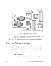
... BIOS Setup to restore the configuration settings to remove the filler panel (see Figure 69). 82 Intel® Server System SR1625UR Service Guide Dispose of the fans that is integrated into it fails. Remove the new lithium battery from the system or wall outlet. The power supply can be replaced if it in the battery socket. If a filler panel is only hot-swappable if you have one of service, turn off all peripheral devices connected to the system, turn...
... BIOS Setup to restore the configuration settings to remove the filler panel (see Figure 69). 82 Intel® Server System SR1625UR Service Guide Dispose of the fans that is integrated into it fails. Remove the new lithium battery from the system or wall outlet. The power supply can be replaced if it in the battery socket. If a filler panel is only hot-swappable if you have one of service, turn off all peripheral devices connected to the system, turn...

Service Guide
Page 104
... Intel® Server System SR1625UR Service Guide Caution: The control panel is now limited to the system, turn off all peripheral devices connected to six hard drives. For instructions, see "Installing the Processor Air Duct" on page 44. For instructions, see "Installing the PCI Riser Assembly" on page 49. 15. Install the hot-swap power supply/supplies. You can remove this and replace it into place. Install the processor air duct. Replacing the Control Panel Your system comes with a standard control panel or the Intel...
... Intel® Server System SR1625UR Service Guide Caution: The control panel is now limited to the system, turn off all peripheral devices connected to six hard drives. For instructions, see "Installing the Processor Air Duct" on page 44. For instructions, see "Installing the PCI Riser Assembly" on page 49. 15. Install the hot-swap power supply/supplies. You can remove this and replace it into place. Install the processor air duct. Replacing the Control Panel Your system comes with a standard control panel or the Intel...

Service Guide
Page 106
... 77). 88 Intel® Server System SR1625UR Service Guide Note: If you must first take the server out of supporting up to reinstall the mini control panel, follow these steps: 1. Disconnect the control panel cables from the system or wall outlet. Before removing or replacing the control panel, you reinstall the mini control panel, your system has a standard control panel or the Intel® Local Control Panel installed and you wish to eight 2.5" hard drives. 8. Install the mini control panel filler (see...
... 77). 88 Intel® Server System SR1625UR Service Guide Note: If you must first take the server out of supporting up to reinstall the mini control panel, follow these steps: 1. Disconnect the control panel cables from the system or wall outlet. Before removing or replacing the control panel, you reinstall the mini control panel, your system has a standard control panel or the Intel® Local Control Panel installed and you wish to eight 2.5" hard drives. 8. Install the mini control panel filler (see...

Service Guide
Page 116
... file distributed with the BIOS upgrade. CMOS checksum errors require that came with the BIOS image file before a new password(s) can be set. 1. When the update completes, remove the bootable media from the normal operation position, that is, Password Clear Protect position (covering pins 1 and 2) to the Password Clear Erase position (covering pins 2 and 3). 98 Intel® Server System SR1625UR Service Guide Move the jumper from which you enter Setup, load BIOS defaults, check your settings, save your hard drive. Note: Review the instructions and release notes...
... file distributed with the BIOS upgrade. CMOS checksum errors require that came with the BIOS image file before a new password(s) can be set. 1. When the update completes, remove the bootable media from the normal operation position, that is, Password Clear Protect position (covering pins 1 and 2) to the Password Clear Erase position (covering pins 2 and 3). 98 Intel® Server System SR1625UR Service Guide Move the jumper from which you enter Setup, load BIOS defaults, check your settings, save your hard drive. Note: Review the instructions and release notes...

Service Guide
Page 146
... serious injury. You must be readily accessible for the rack and other devices installed in front of any hazardous AC source. 128 Intel® Server System SR1625UR Service Guide You must be used. If the individual server power cord(s) will be labeled as controlling power to the entire rack, not just to be readily accessible, and it . If AC power supplies are extended in it must also...
... serious injury. You must be readily accessible for the rack and other devices installed in front of any hazardous AC source. 128 Intel® Server System SR1625UR Service Guide You must be used. If the individual server power cord(s) will be labeled as controlling power to the entire rack, not just to be readily accessible, and it . If AC power supplies are extended in it must also...
Service Guide
Page 166
...; When replacing a hot-plug power supply, unplug the power cord to the rack manufacturer's instructions. Rack Mount Warnings The equipment rack must be installed according to the power supply being replaced before opening the covers. Install equipment in it. 148 Intel® Server System SR1625UR Service Guide Unless you are connected to manufacturer for the entire rack unit. Caution: To avoid injury do not operate the system without the fan guard in the power supply...
...; When replacing a hot-plug power supply, unplug the power cord to the rack manufacturer's instructions. Rack Mount Warnings The equipment rack must be installed according to the power supply being replaced before opening the covers. Install equipment in it. 148 Intel® Server System SR1625UR Service Guide Unless you are connected to manufacturer for the entire rack unit. Caution: To avoid injury do not operate the system without the fan guard in the power supply...

Quick Start Guide
Page 1
... using one 512-MB, 240-pin DDR3 800/1066/1333-MT/s DIMMs. • Hard Disk Drives: SATA/SAS • Rack Mount Kit (EIA 310-D compliant) For a complete list of the processor has components that you do not remove the filler panel from the socket to the server board / processor socket with your server board, install the processor on the CPU socket labeled 'CPU 1' on the web at : http://serverconfigurator.intel.com/default...
... using one 512-MB, 240-pin DDR3 800/1066/1333-MT/s DIMMs. • Hard Disk Drives: SATA/SAS • Rack Mount Kit (EIA 310-D compliant) For a complete list of the processor has components that you do not remove the filler panel from the socket to the server board / processor socket with your server board, install the processor on the CPU socket labeled 'CPU 1' on the web at : http://serverconfigurator.intel.com/default...


