User Guide
Page 5
..., and step by -step instructions and diagrams for installing or replacing components such as the fans, power supply, drives, and other components. Chapter 2 provides a brief overview of reference resources. Manual Organization Chapter 1 provides a list of the server system. Information about the specific BIOS settings and screens is written for a link to update the system. This includes how to navigate through the BIOS Setup screens, how to perform a BIOS update, and how to help...
..., and step by -step instructions and diagrams for installing or replacing components such as the fans, power supply, drives, and other components. Chapter 2 provides a brief overview of reference resources. Manual Organization Chapter 1 provides a list of the server system. Information about the specific BIOS settings and screens is written for a link to update the system. This includes how to navigate through the BIOS Setup screens, how to perform a BIOS update, and how to help...

User Guide
Page 6
... board, installed in the server system • Fan cable, installed in the server system • Chassis intrusion switch, integrated into the server system riser • Attention document, in the server system product box • Quick Start User's Guide, in the server system product box • Two screws for installing the optical drive component, in the hardware box • Rack handles, in the hardware box • USB cable • Peripheral bay filler panel, installed in the server system • Mini control panel, installed in...
... board, installed in the server system • Fan cable, installed in the server system • Chassis intrusion switch, integrated into the server system riser • Attention document, in the server system product box • Quick Start User's Guide, in the server system product box • Two screws for installing the optical drive component, in the hardware box • Rack handles, in the hardware box • USB cable • Peripheral bay filler panel, installed in the server system • Mini control panel, installed in...

User Guide
Page 9
..., but not the board wrapper. System power on a grounded, static free surface. They can damage the contacts inside the jumper, causing intermittent problems with the function controlled by their edges. Some jumpers have such a tab, take care when using this guide or any surface. Gripping the wide sides can be present on top that jumper. Intel® Server System SR1550AL/SR1550ALSAS User's Guide ix To remove power from system, you perform...
..., but not the board wrapper. System power on a grounded, static free surface. They can damage the contacts inside the jumper, causing intermittent problems with the function controlled by their edges. Some jumpers have such a tab, take care when using this guide or any surface. Gripping the wide sides can be present on top that jumper. Intel® Server System SR1550AL/SR1550ALSAS User's Guide ix To remove power from system, you perform...
User Guide
Page 11
.... Light Guided Diagnostic LEDs 10 Figure 7. Front Bezel Supporting the Intel® Local Control Panel 24 Figure 16. Front Bezel Supporting the Mini Control Panel 25 Figure 17. Installing the Interposer Board to the Server Board 48 Intel® Server System SR1550AL/SR1550ALSAS User's Guide xi Installing the PCI-X* Riser Card into the Server System 42 Figure 37. Installing the I/O Expansion Module(s) to the Optical Drive 38 Figure 33. BIOS Select Jumper 8 Figure 5. Front Panel Features and Peripherals 19 Figure 14. Installing the Processor...
.... Light Guided Diagnostic LEDs 10 Figure 7. Front Bezel Supporting the Intel® Local Control Panel 24 Figure 16. Front Bezel Supporting the Mini Control Panel 25 Figure 17. Installing the Interposer Board to the Server Board 48 Intel® Server System SR1550AL/SR1550ALSAS User's Guide xi Installing the PCI-X* Riser Card into the Server System 42 Figure 37. Installing the I/O Expansion Module(s) to the Optical Drive 38 Figure 33. BIOS Select Jumper 8 Figure 5. Front Panel Features and Peripherals 19 Figure 14. Installing the Processor...
User Guide
Page 14
.../SATA Hot-swap Hard Disk Drive 37 Installing or Removing a Slimline Optical Drive or Internal USB Floppy 37 Installing a Slimline Optical Drive or Internal USB Floppy 38 Removing a Slimline Optical Drive or Internal USB Floppy 39 Installing and Removing the PCI Riser Assembly 40 Removing the PCI Riser Assembly 40 Installing the PCI Riser Assembly 41 Replacing the PCI Express* Riser Card with the PCI-X* Riser Card 43 Removing the PCI Express* Riser Card 43 Installing the PCI-X* Riser Card 45 Installing and Removing a PCI Add-in Card 46 Installing a PCI Add-in Card 46 Removing a PCI...
.../SATA Hot-swap Hard Disk Drive 37 Installing or Removing a Slimline Optical Drive or Internal USB Floppy 37 Installing a Slimline Optical Drive or Internal USB Floppy 38 Removing a Slimline Optical Drive or Internal USB Floppy 39 Installing and Removing the PCI Riser Assembly 40 Removing the PCI Riser Assembly 40 Installing the PCI Riser Assembly 41 Replacing the PCI Express* Riser Card with the PCI-X* Riser Card 43 Removing the PCI Express* Riser Card 43 Installing the PCI-X* Riser Card 45 Installing and Removing a PCI Add-in Card 46 Installing a PCI Add-in Card 46 Removing a PCI...
User Guide
Page 15
... Server Utilities 79 Using the BIOS Setup Utility 79 Starting Setup ...79 If You Cannot Access Setup 79 Setup Menus ...79 Upgrading the BIOS ...81 Preparing for the Upgrade 81 Upgrading the BIOS ...82 Clearing the Password ...82 Clearing the CMOS ...83 Appendix A: Technical Reference 85 Cable Routing ...85 750W Single Power Supply Input Voltages 86 750W Single Power Supply Output Voltages 87 System Environmental Specifications 88 Appendix B: Troubleshooting 89 Resetting the System ...89 Problems following Initial System Installation 90 First Steps Checklist ...90 Hardware Diagnostic...
... Server Utilities 79 Using the BIOS Setup Utility 79 Starting Setup ...79 If You Cannot Access Setup 79 Setup Menus ...79 Upgrading the BIOS ...81 Preparing for the Upgrade 81 Upgrading the BIOS ...82 Clearing the Password ...82 Clearing the CMOS ...83 Appendix A: Technical Reference 85 Cable Routing ...85 750W Single Power Supply Input Voltages 86 750W Single Power Supply Output Voltages 87 System Environmental Specifications 88 Appendix B: Troubleshooting 89 Resetting the System ...89 Problems following Initial System Installation 90 First Steps Checklist ...90 Hardware Diagnostic...

User Guide
Page 16
... Safety Instructions 127 English ...127 Deutsch ...129 xvi Intel® Server System SR1550AL/SR1550ALSAS User's Guide System Cooling Fans Do Not Rotate Properly 94 Drive Activity Light Does Not Light 94 CD-ROM Drive or DVD-ROM Drive Activity Light Does Not Light 94 Cannot Connect to a Server 95 Problems with Network 95 System Boots when Installing PCI Card 96 Problems with Newly Installed Application Software 96 Problems with Application Software that Ran Correctly Earlier 96 Devices are not Recognized under Device Manager (Microsoft* Windows* Operating System) ...97 Hard Drive...
... Safety Instructions 127 English ...127 Deutsch ...129 xvi Intel® Server System SR1550AL/SR1550ALSAS User's Guide System Cooling Fans Do Not Rotate Properly 94 Drive Activity Light Does Not Light 94 CD-ROM Drive or DVD-ROM Drive Activity Light Does Not Light 94 Cannot Connect to a Server 95 Problems with Network 95 System Boots when Installing PCI Card 96 Problems with Newly Installed Application Software 96 Problems with Application Software that Ran Correctly Earlier 96 Devices are not Recognized under Device Manager (Microsoft* Windows* Operating System) ...97 Hard Drive...

User Guide
Page 36
... green indicates normal operation. No light indicates POST is running or the system is the Intel® Local Control Panel. Turns on installing the standard control panel, see "Replacing the Control Panel". The other option is off. No light indicates the power is off / is connected. Feature NIC 2 Activity LED NIC 1 Activity LED Power/Sleep Button Power/Sleep LED Hard Disk Drive Activity LED System Status LED System Identification LED System Identification Button Reset Button Function Continuous green light indicates a link between the system and the network to it is in...
... green indicates normal operation. No light indicates POST is running or the system is the Intel® Local Control Panel. Turns on installing the standard control panel, see "Replacing the Control Panel". The other option is off. No light indicates the power is off / is connected. Feature NIC 2 Activity LED NIC 1 Activity LED Power/Sleep Button Power/Sleep LED Hard Disk Drive Activity LED System Status LED System Identification LED System Identification Button Reset Button Function Continuous green light indicates a link between the system and the network to it is in...
User Guide
Page 39
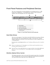
...Bay D. For instructions on installing hard drives, see "Installing and Removing a Hot-swap Hard Drive". Drives must be used with your server system; Slimline Optical Drive Carrier The slimline optical drive carrier can support up to 17 watts of 45C. Front Panel Features and Peripheral Devices The server system provides locations and hardware for an Internet link to a list of supported hardware. With the mini control panel, the system can be purchased separately. See "Server System References" for installing hard drives, a USB floppy drive, CD-ROM drive, or DVD-ROM drive. One...
...Bay D. For instructions on installing hard drives, see "Installing and Removing a Hot-swap Hard Drive". Drives must be used with your server system; Slimline Optical Drive Carrier The slimline optical drive carrier can support up to 17 watts of 45C. Front Panel Features and Peripheral Devices The server system provides locations and hardware for an Internet link to a list of supported hardware. With the mini control panel, the system can be purchased separately. See "Server System References" for installing hard drives, a USB floppy drive, CD-ROM drive, or DVD-ROM drive. One...

User Guide
Page 58
... optical drive tray assembly into place. 9. (Optional) For installing the optional USB floppy drive, note the location of the interposer board plugs into the matching socket on the tray locks into the server system as shown in Figure 33. 7. Make sure that came with the device. 38 Intel® Server System SR1550AL/SR1550ALSAS User's Guide See "Safety Information". 2. Installing a Slimline Optical Drive or Internal USB Floppy 1. Power down the server and unplug all peripheral devices and the AC power cable. 3. Remove...
... optical drive tray assembly into place. 9. (Optional) For installing the optional USB floppy drive, note the location of the interposer board plugs into the matching socket on the tray locks into the server system as shown in Figure 33. 7. Make sure that came with the device. 38 Intel® Server System SR1550AL/SR1550ALSAS User's Guide See "Safety Information". 2. Installing a Slimline Optical Drive or Internal USB Floppy 1. Power down the server and unplug all peripheral devices and the AC power cable. 3. Remove...
User Guide
Page 84
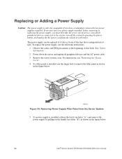
Power down the server and unplug all peripheral devices connected to remove the filler panel as shown in the figure below . 64 Intel® Server System SR1550AL/SR1550ALSAS User's Guide Remove the server system cover. For instructions, see letter "B") as shown in the figure below . The power supply can be replaced if it fails or if one power supply installed, before removing or replacing the power supply, you have one of the fans that is only hot-swappable if...
Power down the server and unplug all peripheral devices connected to remove the filler panel as shown in the figure below . 64 Intel® Server System SR1550AL/SR1550ALSAS User's Guide Remove the server system cover. For instructions, see letter "B") as shown in the figure below . The power supply can be replaced if it fails or if one power supply installed, before removing or replacing the power supply, you have one of the fans that is only hot-swappable if...

User Guide
Page 88
... from the Server System 68 Intel® Server System SR1550AL/SR1550ALSAS User's Guide Press the latch at the beginning of service, turn off all peripheral devices and the AC power cable. 3. Note: If you must be operated with a standard control panel or the Intel® Local Control Panel. Remove the filler panel or two right drive carriers. 7. A B TP02245 Figure 59. Remove the front bezel if it with a control panel installed. For instructions, see "Removing the Chassis Cover". 5. Observe the...
... from the Server System 68 Intel® Server System SR1550AL/SR1550ALSAS User's Guide Press the latch at the beginning of service, turn off all peripheral devices and the AC power cable. 3. Note: If you must be operated with a standard control panel or the Intel® Local Control Panel. Remove the filler panel or two right drive carriers. 7. A B TP02245 Figure 59. Remove the front bezel if it with a control panel installed. For instructions, see "Removing the Chassis Cover". 5. Observe the...
User Guide
Page 90
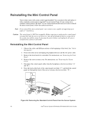
... Server System 70 Intel® Server System SR1550AL/SR1550ALSAS User's Guide Note: If you reinstall the mini control panel, your system has a standard control panel or the Intel® Local Control Panel installed and you must first take the server out of supporting up to eight 2.5" hard drives. Caution: The control panel is installed. Reinstalling the Mini Control Panel 1. Remove the front bezel if it with a mini control panel installed. Remove the server system cover. C A B D TP02256 Figure 62. Power down the server and unplug all peripheral devices connected...
... Server System 70 Intel® Server System SR1550AL/SR1550ALSAS User's Guide Note: If you reinstall the mini control panel, your system has a standard control panel or the Intel® Local Control Panel installed and you must first take the server out of supporting up to eight 2.5" hard drives. Caution: The control panel is installed. Reinstalling the Mini Control Panel 1. Remove the front bezel if it with a mini control panel installed. Remove the server system cover. C A B D TP02256 Figure 62. Power down the server and unplug all peripheral devices connected...

User Guide
Page 103
... Update Mode 2 3 J1D2 Password Reset Disable 2 Enable 3 J1D1 2 Clear 3 CMOS J1D3 Figure 71. Intel® Server System SR1550AL/SR1550ALSAS User's Guide 83 Clear Password Jumper TP02080 4. Reconnect the AC power and power up the server. 8. Clearing the CMOS If you are not able to access the BIOS setup screens, the CMOS Clear jumper will need to be reset by BMC, at pins 1 and 2 to reset the configuration RAM. 1. The password is now cleared and can be used to the CMOS Clear Force Erase position, covering pins 2 and 3. Move the jumper from the normal operation...
... Update Mode 2 3 J1D2 Password Reset Disable 2 Enable 3 J1D1 2 Clear 3 CMOS J1D3 Figure 71. Intel® Server System SR1550AL/SR1550ALSAS User's Guide 83 Clear Password Jumper TP02080 4. Reconnect the AC power and power up the server. 8. Clearing the CMOS If you are not able to access the BIOS setup screens, the CMOS Clear jumper will need to be reset by BMC, at pins 1 and 2 to reset the configuration RAM. 1. The password is now cleared and can be used to the CMOS Clear Force Erase position, covering pins 2 and 3. Move the jumper from the normal operation...
User Guide
Page 110
... system has a hard disk drive, is it properly formatted or configured? • Are all device drivers properly installed? • Are the configuration settings made in boards and peripheral devices correct? Hardware failure is with a specific software application, see "Problems with them. Check the AC cable(s) on the back of the chassis and at the wall outlet? • Are the power supplies plugged in their slots on the server board? • Are all jumper settings on the server board...
... system has a hard disk drive, is it properly formatted or configured? • Are all device drivers properly installed? • Are the configuration settings made in boards and peripheral devices correct? Hardware failure is with a specific software application, see "Problems with them. Check the AC cable(s) on the back of the chassis and at the wall outlet? • Are the power supplies plugged in their slots on the server board? • Are all jumper settings on the server board...

User Guide
Page 111
... according to boot from a USB floppy or from the hard disk drive, make sure there is checked, its brightness and contrast controls to correct the problem. If the power LED does light, attempt to the operating system. Turn on the video monitor. for the following: • Does the drive activity light turn on the screen. Intel® Server System SR1550AL/SR1550ALSAS User's Guide 91 Caution: Turn off devices before disconnecting cables: Before disconnecting any external peripheral devices. Turn off the system and any...
... according to boot from a USB floppy or from the hard disk drive, make sure there is checked, its brightness and contrast controls to correct the problem. If the power LED does light, attempt to the operating system. Turn on the video monitor. for the following: • Does the drive activity light turn on the screen. Intel® Server System SR1550AL/SR1550ALSAS User's Guide 91 Caution: Turn off devices before disconnecting cables: Before disconnecting any external peripheral devices. Turn off the system and any...

User Guide
Page 115
... file. • The controller stopped working without a hub), you will need a crossover cable. • Check the network controller LEDs next to the NIC connectors. Problems with Network The server hangs when the drivers are loaded • Certain drivers may be necessary to alter settings so that interrupts are not shared with your operating system supports shared interrupts. • Try reseating the add-in adapter. Make sure your PCI card(s) for a link to...
... file. • The controller stopped working without a hub), you will need a crossover cable. • Check the network controller LEDs next to the NIC connectors. Problems with Network The server hangs when the drivers are loaded • Certain drivers may be necessary to alter settings so that interrupts are not shared with your operating system supports shared interrupts. • Try reseating the add-in adapter. Make sure your PCI card(s) for a link to...
User Guide
Page 116
... running the software from a CD-ROM or DVD-ROM, try a different disk. • Make sure the correct device drivers installed. Problems with the power button on the front of the system have turned the system power off the server power by file corruption or changes to the software configuration. Faulty equipment is properly installed and configured for the software. System Boots when Installing PCI Card System Management features require full-time "standby" power. Delete and then reinstall the drivers. • Run diagnostics. See the software documentation. • Use...
... running the software from a CD-ROM or DVD-ROM, try a different disk. • Make sure the correct device drivers installed. Problems with the power button on the front of the system have turned the system power off the server power by file corruption or changes to the software configuration. Faulty equipment is properly installed and configured for the software. System Boots when Installing PCI Card System Management features require full-time "standby" power. Delete and then reinstall the drivers. • Run diagnostics. See the software documentation. • Use...
User Guide
Page 117
... Device Manager (Microsoft* Windows* Operating System) The Microsoft* Windows* operating systems do not include all of voltage spikes include a flickering video display, unexpected system reboots, and the system not responding to check your drives. • If using ATA drives, verify that is plugged into the power supply. • Make sure the drive is compatible. See "Server System References" for the server. See "Server System References" for your power budget. • If using a RAID configuration with SCSI or SATA drives, make sure the RAID card is installed...
... Device Manager (Microsoft* Windows* Operating System) The Microsoft* Windows* operating systems do not include all of voltage spikes include a flickering video display, unexpected system reboots, and the system not responding to check your drives. • If using ATA drives, verify that is plugged into the power supply. • Make sure the drive is compatible. See "Server System References" for the server. See "Server System References" for your power budget. • If using a RAID configuration with SCSI or SATA drives, make sure the RAID card is installed...
User Guide
Page 118
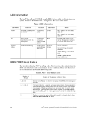
... Control panel and board rear left corner Blue Green or Amber Notes Off = Power is bing used, the server board may be faulty. 98 Intel® Server System SR1550AL/SR1550ALSAS User's Guide POST Error Beep Codes Number of Beeps 1, 2, or 3 4 - 7 or 9 - 11 8 Reason for Beeps and Action to turn the LED on -board video is off . If the beep codes are not generated after the add-in troubleshooting your system manufacturer. Replace or reseat the system video add-in cards and re-start the system. Table 9. Remove...
... Control panel and board rear left corner Blue Green or Amber Notes Off = Power is bing used, the server board may be faulty. 98 Intel® Server System SR1550AL/SR1550ALSAS User's Guide POST Error Beep Codes Number of Beeps 1, 2, or 3 4 - 7 or 9 - 11 8 Reason for Beeps and Action to turn the LED on -board video is off . If the beep codes are not generated after the add-in troubleshooting your system manufacturer. Replace or reseat the system video add-in cards and re-start the system. Table 9. Remove...


