Product Specification
Page 3
...Power Cord Specification Requirements 13 3. Cooling Sub-System ...14 3.1 Power Supply Fans 15 3.2 Processor Air Duct and Air Baffle 15 4. Processor Power Connector 10 2.2.3 P3 - CD Power Connector 11 2.2.6 P7 - SATA Hard Drive Power Connectors 10 2.2.5 P6 - Introduction ...1 1.1 System Views ...1 1.2 System Dimensions 2 1.3 System Components 3 1.4 System Boards ...5 1.5 Hard Drive and Peripheral Bays 5 1.6 Power Sub-System 7 1.7 System Cooling...7 1.8 Rack and Cabinet Mounting Options 7 2. Main Power Connector 9 2.2.2 P2 - Power Sub-System...
...Power Cord Specification Requirements 13 3. Cooling Sub-System ...14 3.1 Power Supply Fans 15 3.2 Processor Air Duct and Air Baffle 15 4. Processor Power Connector 10 2.2.3 P3 - CD Power Connector 11 2.2.6 P7 - SATA Hard Drive Power Connectors 10 2.2.5 P6 - Introduction ...1 1.1 System Views ...1 1.2 System Dimensions 2 1.3 System Components 3 1.4 System Boards ...5 1.5 Hard Drive and Peripheral Bays 5 1.6 Power Sub-System 7 1.7 System Cooling...7 1.8 Rack and Cabinet Mounting Options 7 2. Main Power Connector 9 2.2.2 P2 - Power Sub-System...
Product Specification
Page 4
...Replacing the CMOS Battery 32 9.4 Product Regulatory Compliance 33 9.5 Use of Specified Regulated Components 33 9.6 Electromagnetic Compatibility Notices 35 9.6.1 USA ...35 9.6.2 FCC Verification Statement 36 9.6.3 ICES-003 (Canada 36 9.6.4 Europe (CE Declaration of Contents Intel® Server Systems SR1530CL/SR1530HCL/SR1530HCS and SR1530CLR/SR1530HCLR/SR1530HCLSR 4.2.1 Hot-Swap Hard Disk Drive Trays 19 4.2.2 Drive Blanks...20 4.2.3 System Fan Connectors 21 5. Backplane Board ...27 7.1.1 Hard Drive Activity LED 29 8. Front Control Panel...22 5.1.1 Power/Sleep...
...Replacing the CMOS Battery 32 9.4 Product Regulatory Compliance 33 9.5 Use of Specified Regulated Components 33 9.6 Electromagnetic Compatibility Notices 35 9.6.1 USA ...35 9.6.2 FCC Verification Statement 36 9.6.3 ICES-003 (Canada 36 9.6.4 Europe (CE Declaration of Contents Intel® Server Systems SR1530CL/SR1530HCL/SR1530HCS and SR1530CLR/SR1530HCLR/SR1530HCLSR 4.2.1 Hot-Swap Hard Disk Drive Trays 19 4.2.2 Drive Blanks...20 4.2.3 System Fan Connectors 21 5. Backplane Board ...27 7.1.1 Hard Drive Activity LED 29 8. Front Control Panel...22 5.1.1 Power/Sleep...
Product Specification
Page 5
... System Components - Back Panel Features ...5 Figure 6. Drive Bays - Fan Module Assembly - SR1530HCL/SR1530HCLR (SATA) and SR1530HCLS/SR1530HCLSR (SAS 27 Figure 22. SR1530CL/SR1530CLR (SATA 3 Figure 4. Hard Drive Tray Assembly 20 Figure 17. SR1530HCL/SR1530HCLR (SATA) and SR1530HCLS/SR1530HCLSR (SAS 23 Figure 20. Hot Swap Passive Backplane - SR1530HCL/SR1530HCLR (SATA) and SR1530HCLS/SR1530HCLSR (SAS 4 Figure 5. SR1530CL/SR1530CLR (SATA 22 Figure 19. Diagnostic LED Placement Diagram Example 42 Revision 2.2 v Intel order number D71005-005 Power Supply...
... System Components - Back Panel Features ...5 Figure 6. Drive Bays - Fan Module Assembly - SR1530HCL/SR1530HCLR (SATA) and SR1530HCLS/SR1530HCLSR (SAS 27 Figure 22. SR1530CL/SR1530CLR (SATA 3 Figure 4. Hard Drive Tray Assembly 20 Figure 17. SR1530HCL/SR1530HCLR (SATA) and SR1530HCLS/SR1530HCLSR (SAS 23 Figure 20. Hot Swap Passive Backplane - SR1530HCL/SR1530HCLR (SATA) and SR1530HCLS/SR1530HCLSR (SAS 4 Figure 5. SR1530CL/SR1530CLR (SATA 22 Figure 19. Diagnostic LED Placement Diagram Example 42 Revision 2.2 v Intel order number D71005-005 Power Supply...
Product Specification
Page 6
...23. Main Power Connector Pin-out 9 Table 5. Processor Power Connector Pin-out 10 Table 6. Control Panel LED Functions 23 Table 18. Hard Drive Activity LED for SATA II Drives 29 Table 25. List of Tables Intel® Server Systems SR1530CL/SR1530HCL/SR1530HCS and SR1530CLR/SR1530HCLR/SR1530HCLSR List of Tables Table 1. Intel® Server System SR1530CL/SR1530CLR Dimensions 2 Table 2. Intel® Server Systems SR1530HCL/SR1530HCLR and SR1530HCLS/SR1530HCLSR Dimensions...2 Table 3. Cable Harness Definition 9 Table 4. P2 - P3 - Baseboard Signal Connector Pin-out 10...
...23. Main Power Connector Pin-out 9 Table 5. Processor Power Connector Pin-out 10 Table 6. Control Panel LED Functions 23 Table 18. Hard Drive Activity LED for SATA II Drives 29 Table 25. List of Tables Intel® Server Systems SR1530CL/SR1530HCL/SR1530HCS and SR1530CLR/SR1530HCLR/SR1530HCLSR List of Tables Table 1. Intel® Server System SR1530CL/SR1530CLR Dimensions 2 Table 2. Intel® Server Systems SR1530HCL/SR1530HCLR and SR1530HCLS/SR1530HCLSR Dimensions...2 Table 3. Cable Harness Definition 9 Table 4. P2 - P3 - Baseboard Signal Connector Pin-out 10...

Product Specification
Page 13
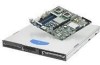
... 2.2 5 Intel order number D71005-005 The supplied EMI gasket must be installed to two fixed 3.5inch SATA (Serial ATA) hard drives and one PCI riser card that are pre-cut, making an I/O shield unnecessary. The following provides a brief description for each: Riser card - A B C D A AC Power Connector B Mouse Socket C PCI Express* Slot D PCI-X* Slot E Keyboard Socket F I E GH J AF001183 F USB Ports 0 and 1 G Serial Port A H Video Connector I NIC 1 Connector (10/100/1000 Mb) J NIC 1 Connector (10/100/1000 Mb) Figure 5. Intel® Server Systems SR1530CL/SR1530HCL/SR1530HCS...
... 2.2 5 Intel order number D71005-005 The supplied EMI gasket must be installed to two fixed 3.5inch SATA (Serial ATA) hard drives and one PCI riser card that are pre-cut, making an I/O shield unnecessary. The following provides a brief description for each: Riser card - A B C D A AC Power Connector B Mouse Socket C PCI Express* Slot D PCI-X* Slot E Keyboard Socket F I E GH J AF001183 F USB Ports 0 and 1 G Serial Port A H Video Connector I NIC 1 Connector (10/100/1000 Mb) J NIC 1 Connector (10/100/1000 Mb) Figure 5. Intel® Server Systems SR1530CL/SR1530HCL/SR1530HCS...
Product Specification
Page 14
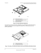
...; Server Systems SR1530HCL/SR1530HCLR and SR1530HCLS/SR1530HCLSR are designed to support up to three hot-swap SATA (Serial ATA) or SAS hard drives and one slimline optical device. SR1530HCL/SR1530HCLR (SATA) and SR1530HCLS/SR1530HCLSR (SAS) 6 Revision 2.2 Intel order number D71005-005 Drive Bays - A Slimline optical drive bay B Hot Swap Hard Drive Bay Figure 7. Introduction Intel® Server Systems SR1530CL/SR1530HCL/SR1530HCS and SR1530CLR/SR1530HCLR/SR1530HCLSR A B C AF001184 A Slimline optical drive bay B Hard drive bay HDD0 (located under the slimline optical drive bay...
...; Server Systems SR1530HCL/SR1530HCLR and SR1530HCLS/SR1530HCLSR are designed to support up to three hot-swap SATA (Serial ATA) or SAS hard drives and one slimline optical device. SR1530HCL/SR1530HCLR (SATA) and SR1530HCLS/SR1530HCLSR (SAS) 6 Revision 2.2 Intel order number D71005-005 Drive Bays - A Slimline optical drive bay B Hot Swap Hard Drive Bay Figure 7. Introduction Intel® Server Systems SR1530CL/SR1530HCL/SR1530HCS and SR1530CLR/SR1530HCLR/SR1530HCLSR A B C AF001184 A Slimline optical drive bay B Hard drive bay HDD0 (located under the slimline optical drive bay...
Product Specification
Page 15
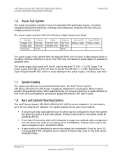
... drive configurations, processors, supported memory, and add-in the table. It provides integrated management features, including over the input voltage ranges shown in cards. 1.8 Rack and Cabinet Mounting Options The Intel® Server System SR1530CL/SR1530CLR (SATA) can be installed in 19-inch wide by up if the AC input is less than 85 VAC +/- 4 VAC. Revision 2.2 7 Intel order number D71005-005 The power supply shall start up to support...
... drive configurations, processors, supported memory, and add-in the table. It provides integrated management features, including over the input voltage ranges shown in cards. 1.8 Rack and Cabinet Mounting Options The Intel® Server System SR1530CL/SR1530CLR (SATA) can be installed in 19-inch wide by up if the AC input is less than 85 VAC +/- 4 VAC. Revision 2.2 7 Intel order number D71005-005 The power supply shall start up to support...

Product Specification
Page 26
Peripheral and Hard Drive Support Intel® Server Systems SR1530CL/SR1530HCL/SR1530HCS and SR1530CLR/SR1530HCLR/SR1530HCLSR Figure 15. The slimline devices are mounted on the server board. 18 Revision 2.2 Intel order number D71005-005 A 44-pin ribbon cable is used to connect the drive assembly to the tray. Drive Bays - Drives are not hot-swappable. 4.1.1 Optical Drive Support The systems support a slimline IDE optical drive. The drive is mounted onto a tool-less drive tray and is then inserted in...
Peripheral and Hard Drive Support Intel® Server Systems SR1530CL/SR1530HCL/SR1530HCS and SR1530CLR/SR1530HCLR/SR1530HCLSR Figure 15. The slimline devices are mounted on the server board. 18 Revision 2.2 Intel order number D71005-005 A 44-pin ribbon cable is used to connect the drive assembly to the tray. Drive Bays - Drives are not hot-swappable. 4.1.1 Optical Drive Support The systems support a slimline IDE optical drive. The drive is mounted onto a tool-less drive tray and is then inserted in...

Product Specification
Page 30
...Front Control Panel - SR1530CL/SR1530CLR (SATA) 22 Revision 2.2 Intel order number D71005-005 Item A B C D E F G AB C EG DF USB port Feature AF001000 Power button. Front Control Panel The standard control panel supports a power and reset buttons, status LED, hard drive activity LED, and NIC 1 and NIC 2 activity LEDs. Front Control Panel Intel® Server Systems SR1530CL/SR1530HCL/SR1530HCS and SR1530CLR/SR1530HCLR/SR1530HCLSR 5. Status LED System power LED Hard drive activity LED NIC 1 LED NIC 2 LED Figure 18. This button also functions as a sleep button if enabled by...
...Front Control Panel - SR1530CL/SR1530CLR (SATA) 22 Revision 2.2 Intel order number D71005-005 Item A B C D E F G AB C EG DF USB port Feature AF001000 Power button. Front Control Panel The standard control panel supports a power and reset buttons, status LED, hard drive activity LED, and NIC 1 and NIC 2 activity LEDs. Front Control Panel Intel® Server Systems SR1530CL/SR1530HCL/SR1530HCS and SR1530CLR/SR1530HCLR/SR1530HCLSR 5. Status LED System power LED Hard drive activity LED NIC 1 LED NIC 2 LED Figure 18. This button also functions as a sleep button if enabled by...

Product Specification
Page 32
... LED should be more than minimum number needed to use all of low-power state. This does not apply to the hard disk. S0 ACPI Steady on System and the operating system are up . ƒ In mirrored configuration, when memory mirroring takes place and system loses memory redundancy. ƒ Redundancy loss such as power-supply or fan. Control Panel LED Operation Color Off Green Green State N/A Solid on . Front Control Panel Intel® Server Systems SR1530CL/SR1530HCL...
... LED should be more than minimum number needed to use all of low-power state. This does not apply to the hard disk. S0 ACPI Steady on System and the operating system are up . ƒ In mirrored configuration, when memory mirroring takes place and system loses memory redundancy. ƒ Redundancy loss such as power-supply or fan. Control Panel LED Operation Color Off Green Green State N/A Solid on . Front Control Panel Intel® Server Systems SR1530CL/SR1530HCL...

Product Specification
Page 33
... window Fatal alarm - power fault ƒ Processor configuration error (for add-in non-redundant mode ƒ IERR signal asserted ƒ Processor 1 missing ƒ Temperature (CPU ThermTrip, memory TempHi, critical threshold crossed) ƒ No power good - Intel® Server Systems SR1530CL/SR1530HCL/SR1530HCS and SR1530CLR/SR1530HCLR/SR1530HCLSR Front Control Panel Color State Amber Blink Criticality Non-critical Amber Solid on the front panel indicates drive activity from the onboard hard disk controllers. Revision 2.2 25 Intel...
... window Fatal alarm - power fault ƒ Processor configuration error (for add-in non-redundant mode ƒ IERR signal asserted ƒ Processor 1 missing ƒ Temperature (CPU ThermTrip, memory TempHi, critical threshold crossed) ƒ No power good - Intel® Server Systems SR1530CL/SR1530HCL/SR1530HCS and SR1530CLR/SR1530HCLR/SR1530HCLSR Front Control Panel Color State Amber Blink Criticality Non-critical Amber Solid on the front panel indicates drive activity from the onboard hard disk controllers. Revision 2.2 25 Intel...
Product Specification
Page 35
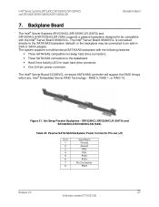
.... ƒ Hard Drive Activity LED for each hard drive connector. ƒ One 2x4-pin power connector. The Intel® Server Board SC000VCL on-board SATA/SAS controller will support the RAID Arrays which are: Intel® Embedded Server RAID Technology - Passive SATA/SAS Backplane Power Connector Pin-out (J7) Pin # 1 2 3 4 5 6 7 8 Signal Name Ground Ground P5V P5V P12V P12V No Connection P3V3 Revision 2.2 27 Intel order number D71005-005 Intel® Server Systems SR1530CL/SR1530HCL/SR1530HCS and SR1530CLR/SR1530HCLR/SR1530HCLSR Backplane Board 7. RAID 0, RAID 1, or RAID 10. SR1530HCL...
.... ƒ Hard Drive Activity LED for each hard drive connector. ƒ One 2x4-pin power connector. The Intel® Server Board SC000VCL on-board SATA/SAS controller will support the RAID Arrays which are: Intel® Embedded Server RAID Technology - Passive SATA/SAS Backplane Power Connector Pin-out (J7) Pin # 1 2 3 4 5 6 7 8 Signal Name Ground Ground P5V P5V P12V P12V No Connection P3V3 Revision 2.2 27 Intel order number D71005-005 Intel® Server Systems SR1530CL/SR1530HCL/SR1530HCS and SR1530CLR/SR1530HCLR/SR1530HCLSR Backplane Board 7. RAID 0, RAID 1, or RAID 10. SR1530HCL...
Product Specification
Page 37
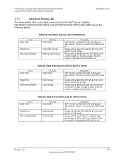
... LED will be off . Hard Drive Activity LED for SAS Drives Status Good Drive Failed Drive Drive during Rebuild LED Color Solid Green Solid Light Orange Blinking Light Orange Description LED will go from solid green to a blinking orange. During a drive failure the LED will stay a solid green color during good drive activity. If there is complete. During a drive rebuild the drive LED will turn off . Hard Drive Activity LED for the Intel® Server Systems SR1530HCL/SR1530HCLR (SATA) and SR1530HCLS...
... LED will be off . Hard Drive Activity LED for SAS Drives Status Good Drive Failed Drive Drive during Rebuild LED Color Solid Green Solid Light Orange Blinking Light Orange Description LED will go from solid green to a blinking orange. During a drive failure the LED will stay a solid green color during good drive activity. If there is complete. During a drive rebuild the drive LED will turn off . Hard Drive Activity LED for the Intel® Server Systems SR1530HCL/SR1530HCLR (SATA) and SR1530HCLS...
Product Specification
Page 38
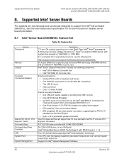
...1000 NICs supporting Intel® I /O Controller Hub. Feature Set Feature Processors Memory Chipset On-board Connectors/Headers Add-in PCI, PCI-X*, PCI Express* Cards On-board Video On-board Hard Drive Controller LAN System Fans System Management Description 771-pin LGA sockets supporting one 3-pin fan header supporting a system fan Support for detailed server board information. 8.1 Intel® Server Board S5000VCL Feature Set Table 26. See the technical product specification for the server board for Intel® System Management Software 30 Revision 2.2 Intel order number D71005...
...1000 NICs supporting Intel® I /O Controller Hub. Feature Set Feature Processors Memory Chipset On-board Connectors/Headers Add-in PCI, PCI-X*, PCI Express* Cards On-board Video On-board Hard Drive Controller LAN System Fans System Management Description 771-pin LGA sockets supporting one 3-pin fan header supporting a system fan Support for detailed server board information. 8.1 Intel® Server Board S5000VCL Feature Set Table 26. See the technical product specification for the server board for Intel® System Management Software 30 Revision 2.2 Intel order number D71005...

Product Specification
Page 39
... sine, 2 g peak, 11 mSec +/-15kV except I/O port +/-8KV per Intel Environmental test specification 2550 BTU/hour 9.2 Serviceability and Availability The system is 30 minutes including diagnosis of the system problem. The desired Mean Time To Repair (MTTR) of the system and having identified the failed component. Remove cover Activity Remove and replace hard disk drive Remove and replace power supply module Remove and replace system fan Remove and replace control panel module Remove and replace baseboard Time Estimate 1 min 5 min 1 min...
... sine, 2 g peak, 11 mSec +/-15kV except I/O port +/-8KV per Intel Environmental test specification 2550 BTU/hour 9.2 Serviceability and Availability The system is 30 minutes including diagnosis of the system problem. The desired Mean Time To Repair (MTTR) of the system and having identified the failed component. Remove cover Activity Remove and replace hard disk drive Remove and replace power supply module Remove and replace system fan Remove and replace control panel module Remove and replace baseboard Time Estimate 1 min 5 min 1 min...

Product Specification
Page 40
... mukaisesti. 32 Revision 2.2 Intel order number D71005-005 VAROITUS Paristo voi räjähtää, jos se on the server board powers the real time clock (RTC) for several years in the RTC (for a list of approved devices. When the battery starts to manufacturer's instructions. ADVARSEL! Udskiftning må kun ske med batteri af samme fabrikat og type. Använd samma...
... mukaisesti. 32 Revision 2.2 Intel order number D71005-005 VAROITUS Paristo voi räjähtää, jos se on the server board powers the real time clock (RTC) for several years in the RTC (for a list of approved devices. When the battery starts to manufacturer's instructions. ADVARSEL! Udskiftning må kun ske med batteri af samme fabrikat og type. Använd samma...

Product Specification
Page 41
..., power supply, and other modules have passed EMC testing using a server board with a microprocessor from the same family (or higher) and operating at the following safety and electromagnetic compatibility (EMC) regulations. Use only the described, regulated components specified in offices, schools, computer rooms, and similar commercial type locations. you must adhere to the assembly instructions in boards containing external power connectors and/or lithium batteries must use...
..., power supply, and other modules have passed EMC testing using a server board with a microprocessor from the same family (or higher) and operating at the following safety and electromagnetic compatibility (EMC) regulations. Use only the described, regulated components specified in offices, schools, computer rooms, and similar commercial type locations. you must adhere to the assembly instructions in boards containing external power connectors and/or lithium batteries must use...
Product Specification
Page 51
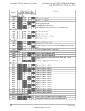
... the memory controller Configuring memory parameters in the memory controller Optimizing memory controller settings Initializing memory, such as ECC init Testing memory Enumerating PCI busses Allocating resources to PCI busses Hot Plug PCI controller initialization Reserved for PCI bus Reserved for PCI bus Reserved for PCI bus Reserved for PCI bus Reserved for PCI bus Resetting USB bus Reserved for USB devices Resetting PATA/SATA bus and all devices Reserved for ATA Resetting SMBUS Reserved for SMBUS Resetting the video controller (VGA) Disabling the video controller (VGA) Enabling the video...
... the memory controller Configuring memory parameters in the memory controller Optimizing memory controller settings Initializing memory, such as ECC init Testing memory Enumerating PCI busses Allocating resources to PCI busses Hot Plug PCI controller initialization Reserved for PCI bus Reserved for PCI bus Reserved for PCI bus Reserved for PCI bus Reserved for PCI bus Resetting USB bus Reserved for USB devices Resetting PATA/SATA bus and all devices Reserved for ATA Resetting SMBUS Reserved for SMBUS Resetting the video controller (VGA) Disabling the video controller (VGA) Enabling the video...
Product Specification
Page 52
... the keyboard Enabling the keyboard Clearing keyboard input buffer Instructing keyboard controller to run Self Test (PS2 only) Resetting the mouse Detecting the mouse Detecting the presence of mouse Enabling the mouse Resetting fixed media device Disabling fixed media device Detecting presence of a fixed media device (IDE hard drive detection, etc.) Enabling/configuring a fixed media device Resetting removable media device Disabling removable media device Detecting presence of a removable media device (IDE CDROM detection, etc.) Enabling/configuring a removable media device Trying boot device...
... the keyboard Enabling the keyboard Clearing keyboard input buffer Instructing keyboard controller to run Self Test (PS2 only) Resetting the mouse Detecting the mouse Detecting the presence of mouse Enabling the mouse Resetting fixed media device Disabling fixed media device Detecting presence of a fixed media device (IDE hard drive detection, etc.) Enabling/configuring a fixed media device Resetting removable media device Disabling removable media device Detecting presence of a removable media device (IDE CDROM detection, etc.) Enabling/configuring a removable media device Trying boot device...

Product Specification
Page 53
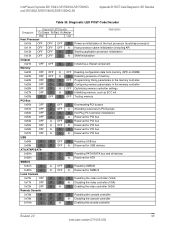
... by software (corrupt flash) R Loading crisis recovery capsule A Handing off control to the crisis recovery capsule A Unable to complete crisis recovery. Revision 2.2 45 Intel order number D71005-005 Intel® Server Systems SR1530CL/SR1530HCL/SR1530HCS and SR1530CLR/SR1530HCLR/SR1530HCLSR Appendix B: POST Code Diagnostic LED Decoder Checkpoint 0xE1h Diagnostic LED Decoder G=Green, R=Red, A=Amber MSB LSB R R R G Description Reserved for initialization module use (PEIM) 0xE3h R R A G Reserved for initialization module use (PEIM) Driver...
... by software (corrupt flash) R Loading crisis recovery capsule A Handing off control to the crisis recovery capsule A Unable to complete crisis recovery. Revision 2.2 45 Intel order number D71005-005 Intel® Server Systems SR1530CL/SR1530HCL/SR1530HCS and SR1530CLR/SR1530HCLR/SR1530HCLSR Appendix B: POST Code Diagnostic LED Decoder Checkpoint 0xE1h Diagnostic LED Decoder G=Green, R=Red, A=Amber MSB LSB R R R G Description Reserved for initialization module use (PEIM) 0xE3h R R A G Reserved for initialization module use (PEIM) Driver...


