Product Specification
Page 3
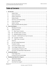
...Introduction ...1 1.1 System Views ...1 1.2 System Dimensions 2 1.3 System Components 3 1.4 System Boards ...5 1.5 Hard Drive and Peripheral Bays 5 1.6 Power Sub-System 7 1.7 System Cooling...7 1.8 Rack and Cabinet Mounting Options 7 2. SATA Hard Drive Power Connectors 10 2.2.5 P6 - Processor Power Connector 10 2.2.3 P3 - Peripheral and Hard Drive Support 17 4.1 Optical Drive Support 18 4.1.1 Optical Drive Support 18 4.2 Hard Disk Drive Support 19 Revision 2.2 iii Intel order number D71005-005 Intel® Server Systems SR1530CL/SR1530HCL/SR1530HCS...
...Introduction ...1 1.1 System Views ...1 1.2 System Dimensions 2 1.3 System Components 3 1.4 System Boards ...5 1.5 Hard Drive and Peripheral Bays 5 1.6 Power Sub-System 7 1.7 System Cooling...7 1.8 Rack and Cabinet Mounting Options 7 2. SATA Hard Drive Power Connectors 10 2.2.5 P6 - Processor Power Connector 10 2.2.3 P3 - Peripheral and Hard Drive Support 17 4.1 Optical Drive Support 18 4.1.1 Optical Drive Support 18 4.2 Hard Disk Drive Support 19 Revision 2.2 iii Intel order number D71005-005 Intel® Server Systems SR1530CL/SR1530HCL/SR1530HCS...
Product Specification
Page 4
... Diagnostic LED Decoder 42 Appendix C: POST Error Beep Codes 46 Glossary...47 Reference Documents ...48 iv Revision 2.2 Intel order number D71005-005 Supported Intel® Server Boards 30 8.1 Intel® Server Board S5000VCL Feature Set 30 9. Front Control Panel...22 5.1.1 Power/Sleep LED 24 5.1.2 System Status LED 24 5.1.3 Drive Activity LED 25 6. Backplane Board ...27 7.1.1 Hard Drive Activity LED 29 8. Environmental and Regulatory Specifications 31 9.1 System Level Environmental Limits 31 9.2 Serviceability and Availability 31 9.3 Replacing the CMOS Battery...
... Diagnostic LED Decoder 42 Appendix C: POST Error Beep Codes 46 Glossary...47 Reference Documents ...48 iv Revision 2.2 Intel order number D71005-005 Supported Intel® Server Boards 30 8.1 Intel® Server Board S5000VCL Feature Set 30 9. Front Control Panel...22 5.1.1 Power/Sleep LED 24 5.1.2 System Status LED 24 5.1.3 Drive Activity LED 25 6. Backplane Board ...27 7.1.1 Hard Drive Activity LED 29 8. Environmental and Regulatory Specifications 31 9.1 System Level Environmental Limits 31 9.2 Serviceability and Availability 31 9.3 Replacing the CMOS Battery...
Product Specification
Page 5
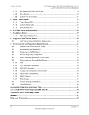
... Control Panel - SR1530HCL/SR1530HCLR (SATA) and SR1530HCLS/SR1530HCLSR (SAS 27 Figure 22. Intel® Server Systems SR1530CL/SR1530HCL/SR1530HCS and SR1530CLR/SR1530HCLR/SR1530HCLSR List of Figures List of Figures Figure 1. Major System Components - Hard Drive Tray Assembly 20 Figure 17. Hot Swap Passive Backplane - Power Supply Mechanical Drawing 8 Figure 9. Drive Tray with Drive Blank 20 Figure 18. PCI Riser Card Assembly 26 Figure 21. Intel® Server System SR1530CL/SR1530CLR (SATA 1 Figure 2. Major System Components - Fan...
... Control Panel - SR1530HCL/SR1530HCLR (SATA) and SR1530HCLS/SR1530HCLSR (SAS 27 Figure 22. Intel® Server Systems SR1530CL/SR1530HCL/SR1530HCS and SR1530CLR/SR1530HCLR/SR1530HCLSR List of Figures List of Figures Figure 1. Major System Components - Hard Drive Tray Assembly 20 Figure 17. Hot Swap Passive Backplane - Power Supply Mechanical Drawing 8 Figure 9. Drive Tray with Drive Blank 20 Figure 18. PCI Riser Card Assembly 26 Figure 21. Intel® Server System SR1530CL/SR1530CLR (SATA 1 Figure 2. Major System Components - Fan...
Product Specification
Page 6
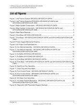
... - Power Supply Efficiency 11 Table 11. Control Panel LED Operation 24 Table 20. System Environmental Limits Summary 31 Table 28. Processor Power Connector Pin-out 10 Table 6. P4 and P5 - System Fan Connector Pin-outs 21 Table 17. Control Panel LED Functions 23 Table 18. SSI Power LED Operation 24 Table 19. Intel® Server System SR1530CL/SR1530CLR Dimensions 2 Table 2. Baseboard Signal Connector Pin-out 10 Table 7. Passive SATA/SAS Backplane I Drives 29 Table 26. Hard Drive Activity LED for SAS Drives...
... - Power Supply Efficiency 11 Table 11. Control Panel LED Operation 24 Table 20. System Environmental Limits Summary 31 Table 28. Processor Power Connector Pin-out 10 Table 6. P4 and P5 - System Fan Connector Pin-outs 21 Table 17. Control Panel LED Functions 23 Table 18. SSI Power LED Operation 24 Table 19. Intel® Server System SR1530CL/SR1530CLR Dimensions 2 Table 2. Baseboard Signal Connector Pin-out 10 Table 7. Passive SATA/SAS Backplane I Drives 29 Table 26. Hard Drive Activity LED for SAS Drives...

Product Specification
Page 13
.... The system supports one slimline optical device. Intel® Server Systems SR1530CL/SR1530HCL/SR1530HCS and SR1530CLR/SR1530HCLR/SR1530HCLSR Introduction Note: The I/O connector locations on the back of the chassis are used as internal interconnects and provide feature accessibility. A B C D A AC Power Connector B Mouse Socket C PCI Express* Slot D PCI-X* Slot E Keyboard Socket F I E GH J AF001183 F USB Ports 0 and 1 G Serial Port A H Video Connector I /O shield unnecessary. The supplied EMI gasket must be installed to two fixed 3.5inch SATA (Serial ATA) hard drives and...
.... The system supports one slimline optical device. Intel® Server Systems SR1530CL/SR1530HCL/SR1530HCS and SR1530CLR/SR1530HCLR/SR1530HCLSR Introduction Note: The I/O connector locations on the back of the chassis are used as internal interconnects and provide feature accessibility. A B C D A AC Power Connector B Mouse Socket C PCI Express* Slot D PCI-X* Slot E Keyboard Socket F I E GH J AF001183 F USB Ports 0 and 1 G Serial Port A H Video Connector I /O shield unnecessary. The supplied EMI gasket must be installed to two fixed 3.5inch SATA (Serial ATA) hard drives and...
Product Specification
Page 14
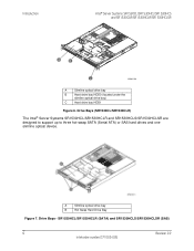
... Server Systems SR1530HCL/SR1530HCLR and SR1530HCLS/SR1530HCLSR are designed to support up to three hot-swap SATA (Serial ATA) or SAS hard drives and one slimline optical device. Drive Bays - SR1530HCL/SR1530HCLR (SATA) and SR1530HCLS/SR1530HCLSR (SAS) 6 Revision 2.2 Intel order number D71005-005 A Slimline optical drive bay B Hot Swap Hard Drive Bay Figure 7. Introduction Intel® Server Systems SR1530CL/SR1530HCL/SR1530HCS and SR1530CLR/SR1530HCLR/SR1530HCLSR A B C AF001184 A Slimline optical drive bay B Hard drive bay HDD0 (located under the slimline optical drive...
... Server Systems SR1530HCL/SR1530HCLR and SR1530HCLS/SR1530HCLSR are designed to support up to three hot-swap SATA (Serial ATA) or SAS hard drives and one slimline optical device. Drive Bays - SR1530HCL/SR1530HCLR (SATA) and SR1530HCLS/SR1530HCLSR (SAS) 6 Revision 2.2 Intel order number D71005-005 A Slimline optical drive bay B Hot Swap Hard Drive Bay Figure 7. Introduction Intel® Server Systems SR1530CL/SR1530HCL/SR1530HCS and SR1530CLR/SR1530HCLR/SR1530HCLSR A B C AF001184 A Slimline optical drive bay B Hard drive bay HDD0 (located under the slimline optical drive...
Product Specification
Page 15
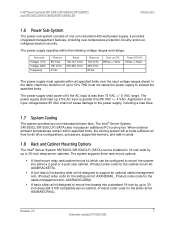
... power supply, including a fuse blow. 1.7 System Cooling The system provides two non-redundant blower fans. Revision 2.2 7 Intel order number D71005-005 The power supply shall start up to 10% THD must operate within specified limits, the cooling system will provide sufficient air flow for the slide rail kit: AXXBASICRAIL). When external ambient temperatures remain within all drive configurations, processors, supported memory, and add-in the table. It provides integrated management...
... power supply, including a fuse blow. 1.7 System Cooling The system provides two non-redundant blower fans. Revision 2.2 7 Intel order number D71005-005 The power supply shall start up to 10% THD must operate within specified limits, the cooling system will provide sufficient air flow for the slide rail kit: AXXBASICRAIL). When external ambient temperatures remain within all drive configurations, processors, supported memory, and add-in the table. It provides integrated management...

Product Specification
Page 26
... allows for an IDE optical CD-ROM, or a DVD/CDR drive. SR1530HCL/SR1530HCLR (SATA) and SR1530HCLS/SR1530HCLSR (SAS) A Slimline optical drive bay B Hot Swap Hard drive bay 4.1 Optical Drive Support The system provides a slimline drive bay that can be configured for easy installation into and removal from the system. Peripheral and Hard Drive Support Intel® Server Systems SR1530CL/SR1530HCL/SR1530HCS and SR1530CLR/SR1530HCLR/SR1530HCLSR Figure 15. Drive Bays - A 44-pin ribbon cable is used to connect the drive assembly to the slimline...
... allows for an IDE optical CD-ROM, or a DVD/CDR drive. SR1530HCL/SR1530HCLR (SATA) and SR1530HCLS/SR1530HCLSR (SAS) A Slimline optical drive bay B Hot Swap Hard drive bay 4.1 Optical Drive Support The system provides a slimline drive bay that can be configured for easy installation into and removal from the system. Peripheral and Hard Drive Support Intel® Server Systems SR1530CL/SR1530HCL/SR1530HCS and SR1530CLR/SR1530HCLR/SR1530HCLSR Figure 15. Drive Bays - A 44-pin ribbon cable is used to connect the drive assembly to the slimline...

Product Specification
Page 30
... USB port Feature AF001000 Power button. Status LED System power LED Hard drive activity LED NIC 1 LED NIC 2 LED Figure 18. The control panel assembly comes pre-assembled into a predefined slot on the front of the system. This button also functions as a sleep button if enabled by an ACPI-compliant operating system. SR1530CL/SR1530CLR (SATA) 22 Revision 2.2 Intel order number D71005-005 Once installed, communication to the server board can be achieved through a standard 24-pin cable connected directly to the server board. Front Control Panel...
... USB port Feature AF001000 Power button. Status LED System power LED Hard drive activity LED NIC 1 LED NIC 2 LED Figure 18. The control panel assembly comes pre-assembled into a predefined slot on the front of the system. This button also functions as a sleep button if enabled by an ACPI-compliant operating system. SR1530CL/SR1530CLR (SATA) 22 Revision 2.2 Intel order number D71005-005 Once installed, communication to the server board can be achieved through a standard 24-pin cable connected directly to the server board. Front Control Panel...

Product Specification
Page 32
... number needed to the hard disk. DC power is off , and the BIOS has not initialized the chipset. Number of low-power state. Note: 1. Front Control Panel Intel® Server Systems SR1530CL/SR1530HCL/SR1530HCS and SR1530CLR/SR1530HCLR/SR1530HCLSR The current limiting resistors for the power LED, the system fault LED, and the NIC LEDs are located on . if there are up . ƒ In mirrored configuration, when memory mirroring takes place and system loses memory...
... number needed to the hard disk. DC power is off , and the BIOS has not initialized the chipset. Number of low-power state. Note: 1. Front Control Panel Intel® Server Systems SR1530CL/SR1530HCL/SR1530HCS and SR1530CLR/SR1530HCLR/SR1530HCLSR The current limiting resistors for the power LED, the system fault LED, and the NIC LEDs are located on . if there are up . ƒ In mirrored configuration, when memory mirroring takes place and system loses memory...

Product Specification
Page 33
... on the front panel indicates drive activity from the onboard hard disk controllers. The Intel® Server Board S5000VCL also provides a header giving access to cool the system not present or failed ƒ In non-sparing and non-mirroring mode if the threshold of ten correctable errors is crossed within the window Fatal alarm - system has failed or shutdown ƒ DIMM failure when there is...
... on the front panel indicates drive activity from the onboard hard disk controllers. The Intel® Server Board S5000VCL also provides a header giving access to cool the system not present or failed ƒ In non-sparing and non-mirroring mode if the threshold of ten correctable errors is crossed within the window Fatal alarm - system has failed or shutdown ƒ DIMM failure when there is...
Product Specification
Page 35
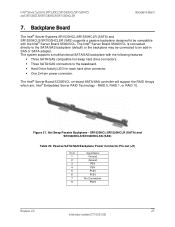
... an add-in SAS or SATA adapter. Hot Swap Passive Backplane - Passive SATA/SAS Backplane Power Connector Pin-out (J7) Pin # 1 2 3 4 5 6 7 8 Signal Name Ground Ground P5V P5V P12V P12V No Connection P3V3 Revision 2.2 27 Intel order number D71005-005 Backplane Board The Intel® Server Systems SR1530HCL/SR1530HCLR (SATA) and SR1530HCLS/SR1530HCLSR (SAS) supports a passive backplane designed to be connected to the baseboard. ƒ Hard Drive Activity LED for each hard drive connector. ƒ One 2x4-pin power connector.
... an add-in SAS or SATA adapter. Hot Swap Passive Backplane - Passive SATA/SAS Backplane Power Connector Pin-out (J7) Pin # 1 2 3 4 5 6 7 8 Signal Name Ground Ground P5V P5V P12V P12V No Connection P3V3 Revision 2.2 27 Intel order number D71005-005 Backplane Board The Intel® Server Systems SR1530HCL/SR1530HCLR (SATA) and SR1530HCLS/SR1530HCLSR (SAS) supports a passive backplane designed to be connected to the baseboard. ƒ Hard Drive Activity LED for each hard drive connector. ƒ One 2x4-pin power connector.
Product Specification
Page 37
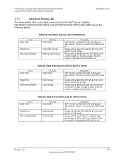
.../SR1530HCLSR Backplane Board 7.1.1 Hard Drive Activity LED The drive activity LED on the hard drive carrier for SATA II Drives Status Good Drive Failed Drive Drive during Rebuild LED Color Solid Green Dark Orange Light Orange Description LED will stay a solid green color during good drive activity. During a drive failure the LED will go from a solid orange to solid dark orange. Table 24. Hard Drive Activity LED for the Intel® Server Systems SR1530HCL/SR1530HCLR (SATA) and SR1530HCLS/SR1530HCLSR...
.../SR1530HCLSR Backplane Board 7.1.1 Hard Drive Activity LED The drive activity LED on the hard drive carrier for SATA II Drives Status Good Drive Failed Drive Drive during Rebuild LED Color Solid Green Dark Orange Light Orange Description LED will stay a solid green color during good drive activity. During a drive failure the LED will go from a solid orange to solid dark orange. Table 24. Hard Drive Activity LED for the Intel® Server Systems SR1530HCL/SR1530HCLR (SATA) and SR1530HCLS/SR1530HCLSR...
Product Specification
Page 38
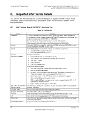
... series, with system bus speeds of 1066 MHz or 1333 MHz For a complete list of providing two USB 2.0 ports ƒ One DH10 Serial B header ƒ Six SATA ports or four SAS ports via the Intel® 6321ESB I /O) ATA/100 connector for detailed server board information. 8.1 Intel® Server Board S5000VCL Feature Set Table 26. Feature Set Feature Processors Memory Chipset On-board Connectors/Headers Add-in PCI, PCI-X*, PCI Express* Cards On-board Video On-board Hard Drive Controller LAN System Fans System Management Description 771-pin LGA sockets supporting one 3-pin fan...
... series, with system bus speeds of 1066 MHz or 1333 MHz For a complete list of providing two USB 2.0 ports ƒ One DH10 Serial B header ƒ Six SATA ports or four SAS ports via the Intel® 6321ESB I /O) ATA/100 connector for detailed server board information. 8.1 Intel® Server Board S5000VCL Feature Set Table 26. Feature Set Feature Processors Memory Chipset On-board Connectors/Headers Add-in PCI, PCI-X*, PCI Express* Cards On-board Video On-board Hard Drive Controller LAN System Fans System Management Description 771-pin LGA sockets supporting one 3-pin fan...

Product Specification
Page 39
.... Remove cover Activity Remove and replace hard disk drive Remove and replace power supply module Remove and replace system fan Remove and replace control panel module Remove and replace baseboard Time Estimate 1 min 5 min 1 min 7 min 2 min 15 min Revision 2.2 31 Intel order number D71005-005 Following are the maximum times that a trained field service technician should take to perform the listed system maintenance procedures, after diagnosis of the system is designed to minimize the MTTR. Intel® Server Systems SR1530CL/SR1530HCL...
.... Remove cover Activity Remove and replace hard disk drive Remove and replace power supply module Remove and replace system fan Remove and replace control panel module Remove and replace baseboard Time Estimate 1 min 5 min 1 min 7 min 2 min 15 min Revision 2.2 31 Intel order number D71005-005 Following are the maximum times that a trained field service technician should take to perform the listed system maintenance procedures, after diagnosis of the system is designed to minimize the MTTR. Intel® Server Systems SR1530CL/SR1530HCL...

Product Specification
Page 40
... paristo ainoastaan laitevalmistajan suosittelemaan tyyppiin. When the battery starts to manufacturer's instructions. Levér det brugte batteri tilbage til leverandøren. Contact your customer service representative or dealer for example, the date and time) may be wrong. ADVARSEL! Environmental and Regulatory Specifications Intel® Server Systems SR1530CL/SR1530HCL/SR1530HCS and SR1530CLR/SR1530HCLR/SR1530HCLSR 9.3 Replacing the CMOS Battery The lithium battery on virheellisesti asennettu.
... paristo ainoastaan laitevalmistajan suosittelemaan tyyppiin. When the battery starts to manufacturer's instructions. Levér det brugte batteri tilbage til leverandøren. Contact your customer service representative or dealer for example, the date and time) may be wrong. ADVARSEL! Environmental and Regulatory Specifications Intel® Server Systems SR1530CL/SR1530HCL/SR1530HCS and SR1530CLR/SR1530HCLR/SR1530HCLSR 9.3 Replacing the CMOS Battery The lithium battery on virheellisesti asennettu.

Product Specification
Page 41
... of the power supply. Add-in boards containing external power connectors and/or lithium batteries must be UL listed. Use of other products/components will void the UL listing and other product certifications and approvals. Updated product information for other product categories and environments (such as: medical, industrial, telecommunications, NEBS, residential, alarm systems, test equipment, etc.), other modules have access to . Intel® Server Systems SR1530CL/SR1530HCL/SR1530HCS and...
... of the power supply. Add-in boards containing external power connectors and/or lithium batteries must be UL listed. Use of other products/components will void the UL listing and other product certifications and approvals. Updated product information for other product categories and environments (such as: medical, industrial, telecommunications, NEBS, residential, alarm systems, test equipment, etc.), other modules have access to . Intel® Server Systems SR1530CL/SR1530HCL/SR1530HCS and...
Product Specification
Page 51
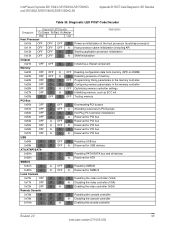
...Reserved for PCI bus Reserved for PCI bus Reserved for PCI bus Resetting USB bus Reserved for USB devices Resetting PATA/SATA bus and all devices Reserved for ATA Resetting SMBUS Reserved for SMBUS Resetting the video controller (VGA) Disabling the video controller (VGA) Enabling the video controller (VGA) Resetting the console controller Disabling the console controller Enabling the console controller Revision 2.2 43 Intel order number D71005-005 Intel® Server Systems SR1530CL/SR1530HCL/SR1530HCS and SR1530CLR/SR1530HCLR/SR1530HCLSR Appendix B: POST Code Diagnostic LED Decoder Table...
...Reserved for PCI bus Reserved for PCI bus Reserved for PCI bus Resetting USB bus Reserved for USB devices Resetting PATA/SATA bus and all devices Reserved for ATA Resetting SMBUS Reserved for SMBUS Resetting the video controller (VGA) Disabling the video controller (VGA) Enabling the video controller (VGA) Resetting the console controller Disabling the console controller Enabling the console controller Revision 2.2 43 Intel order number D71005-005 Intel® Server Systems SR1530CL/SR1530HCL/SR1530HCS and SR1530CLR/SR1530HCLR/SR1530HCLSR Appendix B: POST Code Diagnostic LED Decoder Table...
Product Specification
Page 52
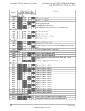
... the keyboard Enabling the keyboard Clearing keyboard input buffer Instructing keyboard controller to run Self Test (PS2 only) Resetting the mouse Detecting the mouse Detecting the presence of mouse Enabling the mouse Resetting fixed media device Disabling fixed media device Detecting presence of a fixed media device (IDE hard drive detection, etc.) Enabling/configuring a fixed media device Resetting removable media device Disabling removable media device Detecting presence of a removable media device (IDE CDROM detection, etc.) Enabling/configuring a removable media device Trying boot device...
... the keyboard Enabling the keyboard Clearing keyboard input buffer Instructing keyboard controller to run Self Test (PS2 only) Resetting the mouse Detecting the mouse Detecting the presence of mouse Enabling the mouse Resetting fixed media device Disabling fixed media device Detecting presence of a fixed media device (IDE hard drive detection, etc.) Enabling/configuring a fixed media device Resetting removable media device Disabling removable media device Detecting presence of a removable media device (IDE CDROM detection, etc.) Enabling/configuring a removable media device Trying boot device...

Product Specification
Page 53
... silent boot is enabled. 0xEFh A A A G Unrecoverable boot failure/S3 resume failure Runtime Phase/EFI Operating System Boot 0xF4h R A R R Entering Sleep state 0xF5h R A R A Exiting Sleep state 0xF8h A R R R Operating system has requested EFI to close boot services (ExitBootServices ( ) has been called) 0xF9h A R R A Operating system has switched to virtual address mode (SetVirtualAddressMap ( ) has been called) 0xFAh A R A R Operating system has requested the system to reset (ResetSystem () has been called) Pre-EFI Initialization Module (PEIM)/Recovery 0x30h...
... silent boot is enabled. 0xEFh A A A G Unrecoverable boot failure/S3 resume failure Runtime Phase/EFI Operating System Boot 0xF4h R A R R Entering Sleep state 0xF5h R A R A Exiting Sleep state 0xF8h A R R R Operating system has requested EFI to close boot services (ExitBootServices ( ) has been called) 0xF9h A R R A Operating system has switched to virtual address mode (SetVirtualAddressMap ( ) has been called) 0xFAh A R A R Operating system has requested the system to reset (ResetSystem () has been called) Pre-EFI Initialization Module (PEIM)/Recovery 0x30h...


