
User Guide
Page 1
Intel® Server System SR1530CL / SR1530HCL / SR1530HCLS and Intel® Server System SR1530CLR / SR1530HCLR / SR1530HCLSR User Guide A Guide for Technically Qualified Assemblers of Intel® Identified Subassemblies/Products Intel Order Number D68456-005
Intel® Server System SR1530CL / SR1530HCL / SR1530HCLS and Intel® Server System SR1530CLR / SR1530HCLR / SR1530HCLSR User Guide A Guide for Technically Qualified Assemblers of Intel® Identified Subassemblies/Products Intel Order Number D68456-005
User Guide
Page 7
... this chapter for step-by step instructions on how to add and replace components on using the Intel® Server System SR1530CL / SR1530HCL / SR1530HCLS and/or the Intel® Server System SR1530CLR / SR1530HCLR / SR1530HCLSR. This manual is available in the Intel® Server Board S5000VCL Technical Product Specification. Preface About this Manual Thank you for purchasing and using the utilities...
... this chapter for step-by step instructions on how to add and replace components on using the Intel® Server System SR1530CL / SR1530HCL / SR1530HCLS and/or the Intel® Server System SR1530CLR / SR1530HCLR / SR1530HCLSR. This manual is available in the Intel® Server Board S5000VCL Technical Product Specification. Preface About this Manual Thank you for purchasing and using the utilities...
User Guide
Page 8
... control panel, installed in the server system • One rail kit, in the server system • Two system blowers, with the Intel® Server Board S5000VCLR. Intel® Server System Contents Your Intel® Server System SR1530CL / SR1530HCL / SR1530HCLS and/or the Intel® Server System SR1530CLR / SR1530HCLR / SR1530HCLSR ships with the following items: • One Intel® Server Board S5000VCL/S5000VCLR, installed in the server system • One 400-watt power...
... control panel, installed in the server system • One rail kit, in the server system • Two system blowers, with the Intel® Server Board S5000VCLR. Intel® Server System Contents Your Intel® Server System SR1530CL / SR1530HCL / SR1530HCLS and/or the Intel® Server System SR1530CLR / SR1530HCLR / SR1530HCLSR ships with the following items: • One Intel® Server Board S5000VCL/S5000VCLR, installed in the server system • One 400-watt power...

User Guide
Page 9
... box Spares and Configuration Guide Found at: available from your Intel field representative or on the Server Configurator Tool at : http://support.intel.com/support/motherboards/server/ S5000VCL/ Intel® Server System SR1530CL / SR1530HCL / SR1530HCLS Quick Start User's Guide Intel® Server System SR1530CLR / SR1530HCLR / SR1530HCLSR Quick Start User's Guide Found in the server system product box - One front panel cable, installed in the...
... box Spares and Configuration Guide Found at: available from your Intel field representative or on the Server Configurator Tool at : http://support.intel.com/support/motherboards/server/ S5000VCL/ Intel® Server System SR1530CL / SR1530HCL / SR1530HCLS Quick Start User's Guide Intel® Server System SR1530CLR / SR1530HCLR / SR1530HCLSR Quick Start User's Guide Found in the server system product box - One front panel cable, installed in the...

User Guide
Page 11
... importantes iii Warnings ...v Preface ...vii About this Manual ...vii Manual Organization ...vii Product Contents ...vii Intel® Server System Contents viii Server System References ix Chapter 1: Server System Features 1 Chassis Component Identification 4 Front Control Panel (SR1530CL/SR1530CLR 4 Front Control Panel (SR1530HCL/SR1530HCLS and SR1530HCLR/SR1530HCLSR) 5 System Rear ...6 Peripheral Devices ...7 Internal Components 10 Configuration Jumpers ...13 RAID Support ...14 Rack-Mounted...
... importantes iii Warnings ...v Preface ...vii About this Manual ...vii Manual Organization ...vii Product Contents ...vii Intel® Server System Contents viii Server System References ix Chapter 1: Server System Features 1 Chassis Component Identification 4 Front Control Panel (SR1530CL/SR1530CLR 4 Front Control Panel (SR1530HCL/SR1530HCLS and SR1530HCLR/SR1530HCLSR) 5 System Rear ...6 Peripheral Devices ...7 Internal Components 10 Configuration Jumpers ...13 RAID Support ...14 Rack-Mounted...

User Guide
Page 12
...Bezel 26 Removing the Front Bezel 26 Installing the Front Bezel 27 Removing and Installing the Server Cover 28 Removing the Server System Cover 28 Installing the Server System Cover 30 Removing and Installing the Processor Air Duct 32 Removing the Processor Air Duct ... Heat Sink 40 Removing the Heat Sink and Processor 41 Installing and Removing a Hard Drive (SR1530CL/SR1530CLR 42 Installing a Hard Disk Drive (SR1530CL/SR1530CLR 42 Removing a Hard Disk Drive (SR1530CL/SR1530CLR 46 Installing and Removing a Hot-Swap SAS/SATA Drive (SR1530HCL/SR1530HCLS and SR1530HCLR/SR1530HCLSR 47 ...
...Bezel 26 Removing the Front Bezel 26 Installing the Front Bezel 27 Removing and Installing the Server Cover 28 Removing the Server System Cover 28 Installing the Server System Cover 30 Removing and Installing the Processor Air Duct 32 Removing the Processor Air Duct ... Heat Sink 40 Removing the Heat Sink and Processor 41 Installing and Removing a Hard Drive (SR1530CL/SR1530CLR 42 Installing a Hard Disk Drive (SR1530CL/SR1530CLR 42 Removing a Hard Disk Drive (SR1530CL/SR1530CLR 46 Installing and Removing a Hot-Swap SAS/SATA Drive (SR1530HCL/SR1530HCLS and SR1530HCLR/SR1530HCLSR 47 ...

User Guide
Page 13
... the Server Board 69 Removing the Server Board 71 Replacing the CMOS Battery 72 Replacing the Power Supply (SR1530CL/SR1530CLR 73 Replacing the Power Supply (SR1530HCL/SR1530HCLS and SR1530HCLR/ SR1530HCLSR) ...78 Replacing the Front Panel Board (SR1530CL/SR1530CLR 83 Replacing the Front Panel Board (SR1530HCL/SR1530HCLR 85 Replacing a System Blower 88 Replacing the System Blowers (SR1530CL/SR1530CLR 88 Replacing a System Blower...
... the Server Board 69 Removing the Server Board 71 Replacing the CMOS Battery 72 Replacing the Power Supply (SR1530CL/SR1530CLR 73 Replacing the Power Supply (SR1530HCL/SR1530HCLS and SR1530HCLR/ SR1530HCLSR) ...78 Replacing the Front Panel Board (SR1530CL/SR1530CLR 83 Replacing the Front Panel Board (SR1530HCL/SR1530HCLR 85 Replacing a System Blower 88 Replacing the System Blowers (SR1530CL/SR1530CLR 88 Replacing a System Blower...
User Guide
Page 17
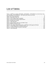
... Specifications 103 Table 6. NIC LED Descriptions 6 Table 3. LED Information ...114 Table 8. Error Beep Codes Generated by Intel® Remote Management Module 116 Table 11. Product Regulatory Compliance Markings 158 Table 12. Product Ecology Compliance Markings 164 Table 13. Intel® Server System SR1530CL / SR1530HCL / SR1530HCLS and Intel Server System SR1530CLR / SR1530HCLR / SR1530HCLSR Feature Summary 2 Table 2. List of Tables Table 1.
... Specifications 103 Table 6. NIC LED Descriptions 6 Table 3. LED Information ...114 Table 8. Error Beep Codes Generated by Intel® Remote Management Module 116 Table 11. Product Regulatory Compliance Markings 158 Table 12. Product Ecology Compliance Markings 164 Table 13. Intel® Server System SR1530CL / SR1530HCL / SR1530HCLS and Intel Server System SR1530CLR / SR1530HCLR / SR1530HCLSR Feature Summary 2 Table 2. List of Tables Table 1.
User Guide
Page 19
...)...33 Figure 26. Lifting the Processor Socket Handle 38 Figure 30. Intel® Server System SR1530CL/SR1530CLR 1 Figure 2. Installing the Server System Cover (SR1530CL/SR1530CLR 31 Figure 23. Opening the Load Plate 38 Figure 31. Chassis Components (SR1530CL/SR1530CLR 10 Figure 9. Removing the Processor Air Duct (SR1530CL/SR1530CLR 32 Figure 25. Intel® Server System SR1530HCL / SR1530HCLS and SR1530HCLR / SR1530HCLSR ...1 Figure 3. Clear Password Jumper 21 Figure...
...)...33 Figure 26. Lifting the Processor Socket Handle 38 Figure 30. Intel® Server System SR1530CL/SR1530CLR 1 Figure 2. Installing the Server System Cover (SR1530CL/SR1530CLR 31 Figure 23. Opening the Load Plate 38 Figure 31. Chassis Components (SR1530CL/SR1530CLR 10 Figure 9. Removing the Processor Air Duct (SR1530CL/SR1530CLR 32 Figure 25. Intel® Server System SR1530HCL / SR1530HCLS and SR1530HCLR / SR1530HCLSR ...1 Figure 3. Clear Password Jumper 21 Figure...

User Guide
Page 20
.../SR1530HCLSR 62 Figure 63. Removing Drive Carrier from the Optical Drive Bracket (SR1530CL/SR1530CLR) 59 Figure 59. Attaching the Bracket to the Optical Drive (SR1530CL/SR1530CLR 53 Figure 50. Installing the Optical Drive into the Server System (SR1530CL/SR1530CLR) ..... 54 Figure 51. Removing the Brackets from the Server System (SR1530CL/SR1530CLR) ........ 46 Figure 41. Removing Interposer Board fromOptical Drive (SR1530HCL/SR1530HCLS and...
.../SR1530HCLSR 62 Figure 63. Removing Drive Carrier from the Optical Drive Bracket (SR1530CL/SR1530CLR) 59 Figure 59. Attaching the Bracket to the Optical Drive (SR1530CL/SR1530CLR 53 Figure 50. Installing the Optical Drive into the Server System (SR1530CL/SR1530CLR) ..... 54 Figure 51. Removing the Brackets from the Server System (SR1530CL/SR1530CLR) ........ 46 Figure 41. Removing Interposer Board fromOptical Drive (SR1530HCL/SR1530HCLS and...
User Guide
Page 21
.... Data Cable Routing (SR1530HCL/SR1530HCLS and SR1530HCLR/ SR1530HCLSR)...101 Server System User Guide xxi Connecting Power Cables (SR1530CL/SR1530CLR 77 Figure 77. Disconnecting System Blower Cables (SR1530CL/SR1530CLR 88 Figure 88. Removing Light Pipes from Blower Bracket (SR1530CL/SR1530CLR 90 Figure 90. Removing Blower Bracket with System Blowers from the Server System (SR1530CL/SR1530CLR)....... 75 Figure 75. Removing an Add-In Card 69 Figure...
.... Data Cable Routing (SR1530HCL/SR1530HCLS and SR1530HCLR/ SR1530HCLSR)...101 Server System User Guide xxi Connecting Power Cables (SR1530CL/SR1530CLR 77 Figure 77. Disconnecting System Blower Cables (SR1530CL/SR1530CLR 88 Figure 88. Removing Light Pipes from Blower Bracket (SR1530CL/SR1530CLR 90 Figure 90. Removing Blower Bracket with System Blowers from the Server System (SR1530CL/SR1530CLR)....... 75 Figure 75. Removing an Add-In Card 69 Figure...

User Guide
Page 23
Intel® Server System SR1530CL/SR1530CLR Figure 2. This chapter provides a illustrations of the product, a list of the server system features, and diagrams showing the location of the server system. 1 Server System Features This chapter briefly describes the main features of important components and connections on the server system. Figure 1. Intel® Server System SR1530HCL / SR1530HCLS and SR1530HCLR / SR1530HCLSR Server System User Guide 1
Intel® Server System SR1530CL/SR1530CLR Figure 2. This chapter provides a illustrations of the product, a list of the server system features, and diagrams showing the location of the server system. 1 Server System Features This chapter briefly describes the main features of important components and connections on the server system. Figure 1. Intel® Server System SR1530HCL / SR1530HCLS and SR1530HCLR / SR1530HCLSR Server System User Guide 1

User Guide
Page 24
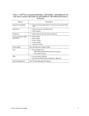
...GB maximum memory Intel® 5000V Chipset, consisting of the server system. Table 1. Intel® Server System SR1530CL / SR1530HCL / SR1530HCLS and Intel Server System SR1530CLR / SR1530HCLR / SR1530HCLSR Feature Summary Feature Description Dimensions (SR1530CL/ SR1530CLR) Dimensions (SR1530HCL/ SR1530HCLS and SR1530HCLR/ SR1530HCLSR) Server Board Processor Memory... Intel® Server Board S5000VCL/S5000VCLR Support for 10/100/1000 Mb connections • Two USB 2.0 ports Internal connections: • One USB port header, which supports two USB 2.0 ports • (SR1530CL/SR1530HCL...
...GB maximum memory Intel® 5000V Chipset, consisting of the server system. Table 1. Intel® Server System SR1530CL / SR1530HCL / SR1530HCLS and Intel Server System SR1530CLR / SR1530HCLR / SR1530HCLSR Feature Summary Feature Description Dimensions (SR1530CL/ SR1530CLR) Dimensions (SR1530HCL/ SR1530HCLS and SR1530HCLR/ SR1530HCLSR) Server Board Processor Memory... Intel® Server Board S5000VCL/S5000VCLR Support for 10/100/1000 Mb connections • Two USB 2.0 ports Internal connections: • One USB port header, which supports two USB 2.0 ports • (SR1530CL/SR1530HCL...
User Guide
Page 25
... USB port • One internal USB header providing two USB ports Intel® System Management Software Server System User Guide 3 Intel® Server System SR1530CL / SR1530HCL / SR1530HCLS and Intel Server System SR1530CLR / SR1530HCLR / SR1530HCLSR Feature Summary Feature Expansion Capabilities Hard Drives Peripherals Front control panel LEDs and buttons Power Supply Fans USB System Management Description • Supports one full-height PCI-X* card and...
... USB port • One internal USB header providing two USB ports Intel® System Management Software Server System User Guide 3 Intel® Server System SR1530CL / SR1530HCL / SR1530HCLS and Intel Server System SR1530CLR / SR1530HCLR / SR1530HCLSR Feature Summary Feature Expansion Capabilities Hard Drives Peripherals Front control panel LEDs and buttons Power Supply Fans USB System Management Description • Supports one full-height PCI-X* card and...

User Guide
Page 26
Front Controls and LEDs (SR1530CL/SR1530CLR) 4 Server System User Guide If you are near the system, you identify the components of your server system. Power Button C. NIC1 LED G. System Power LED E. NIC2 LED Figure 3. USB Port B. A B CD F EG AF001182 A. Front Control Panel (SR1530CL/SR1530CLR) The front control panel of the Intel® Server System SR1530CL/SR1530CLR includes the following buttons and LEDs. Chassis Component Identification This...
Front Controls and LEDs (SR1530CL/SR1530CLR) 4 Server System User Guide If you are near the system, you identify the components of your server system. Power Button C. NIC1 LED G. System Power LED E. NIC2 LED Figure 3. USB Port B. A B CD F EG AF001182 A. Front Control Panel (SR1530CL/SR1530CLR) The front control panel of the Intel® Server System SR1530CL/SR1530CLR includes the following buttons and LEDs. Chassis Component Identification This...

User Guide
Page 29
Slimline Optical Drive Bay B. Hard Disk Drive Bay HDD1 Figure 6. Hard Disk Drive Bay HDD0 (located under the slimline optical drive bay) C. The following figure shows the available options. Optional Peripherals (SR1530CL/SR1530CLR) Server System User Guide 7 A. Peripheral Devices The server system provides locations and hardware for installing hard drives, CD-ROM drive, or DVD-ROM drive. A B C AF001184 . The drives must be purchased separately.
Slimline Optical Drive Bay B. Hard Disk Drive Bay HDD1 Figure 6. Hard Disk Drive Bay HDD0 (located under the slimline optical drive bay) C. The following figure shows the available options. Optional Peripherals (SR1530CL/SR1530CLR) Server System User Guide 7 A. Peripheral Devices The server system provides locations and hardware for installing hard drives, CD-ROM drive, or DVD-ROM drive. A B C AF001184 . The drives must be purchased separately.
User Guide
Page 31
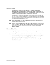
.... Note: Drives can be connected to 17 watts of supported hardware. Hard Disk Drives The Intel® Server System SR1530CL/SR1530CLR and Intel® Server System SR1530HCL/SR1530HCLR provide six SATA ports and one IDE connection. An IDE device can consume up ... see "Installing or Removing a Slimline Optical Drive" on page ix for these drives. Server System User Guide 9 Note: The Intel® Server System SR1530CL / SR1530HCL / SR1530HCLS and the Intel® Server System SR1530CLR / SR1530HCLR / SR1530HCLSR do not support all slimline optical drives. The two SATA and...
.... Note: Drives can be connected to 17 watts of supported hardware. Hard Disk Drives The Intel® Server System SR1530CL/SR1530CLR and Intel® Server System SR1530HCL/SR1530HCLR provide six SATA ports and one IDE connection. An IDE device can consume up ... see "Installing or Removing a Slimline Optical Drive" on page ix for these drives. Server System User Guide 9 Note: The Intel® Server System SR1530CL / SR1530HCL / SR1530HCLS and the Intel® Server System SR1530CLR / SR1530HCLR / SR1530HCLSR do not support all slimline optical drives. The two SATA and...

User Guide
Page 32
PCI Add-in Card Bracket E. Processor Air Duct D. Hard Drive Brackets (two) J. System Blowers (two) I A E F G H AF001185 A. Chassis Components (SR1530CL/SR1530CLR) 10 Server System User Guide Control Panel K. Processor Sockets (two) H. Slimline Optical Drive Bay Figure 8. Power Supply G. Internal Components D C B A K J I . System Memory DIMM Sockets F. Rack Handles (two) B. PCI Cooling Fan C.
PCI Add-in Card Bracket E. Processor Air Duct D. Hard Drive Brackets (two) J. System Blowers (two) I A E F G H AF001185 A. Chassis Components (SR1530CL/SR1530CLR) 10 Server System User Guide Control Panel K. Processor Sockets (two) H. Slimline Optical Drive Bay Figure 8. Power Supply G. Internal Components D C B A K J I . System Memory DIMM Sockets F. Rack Handles (two) B. PCI Cooling Fan C.

User Guide
Page 36
... RAID support. • Enhanced is included on setting up RAID, see the Intel® Server Board S5000VCL Technical Product Specification. The Intel® Embedded Server RAID Technology II feature provides RAID modes 0, 1, and 10. RAID Support The Intel® Server System SR1530CL / SR1530HCL / SR1530HCLS and the Intel® Server System SR1530CLR / SR1530HCLR / SR1530HCLSR provide SATA support.The embedded SATA controller supports both...
... RAID support. • Enhanced is included on setting up RAID, see the Intel® Server Board S5000VCL Technical Product Specification. The Intel® Embedded Server RAID Technology II feature provides RAID modes 0, 1, and 10. RAID Support The Intel® Server System SR1530CL / SR1530HCL / SR1530HCLS and the Intel® Server System SR1530CLR / SR1530HCLR / SR1530HCLSR provide SATA support.The embedded SATA controller supports both...

User Guide
Page 37
... . Memory The Intel® Server System SR1530CL / SR1530HCL / SR1530HCLS and the Intel® Server System SR1530CLR / SR1530HCLR / SR1530HCLSR provide six DIMM sockets across two channels, Channel A and Channel B. Channel A consists of qualified components, see http:// support.intel.com/support/motherboards/s5000vsl/sb/CS-023399.htm. DIMM A3 DIMM A2 DIMM A1 DIMM B1 DIMM B2 DIMM B3 Server System User Guide...
... . Memory The Intel® Server System SR1530CL / SR1530HCL / SR1530HCLS and the Intel® Server System SR1530CLR / SR1530HCLR / SR1530HCLSR provide six DIMM sockets across two channels, Channel A and Channel B. Channel A consists of qualified components, see http:// support.intel.com/support/motherboards/s5000vsl/sb/CS-023399.htm. DIMM A3 DIMM A2 DIMM A1 DIMM B1 DIMM B2 DIMM B3 Server System User Guide...

