
User Guide
Page 5
..., never the wide sides. If your server when handling parts. Turn off the system AC power. Otherwise, personal injury or equipment damage can damage the contacts inside the jumper, causing intermittent problems with the function controlled by that slips over any other tool you use to remove a jumper, or you must adhere to the safety instructions. Hold boards only by wearing an antistatic wrist...
..., never the wide sides. If your server when handling parts. Turn off the system AC power. Otherwise, personal injury or equipment damage can damage the contacts inside the jumper, causing intermittent problems with the function controlled by that slips over any other tool you use to remove a jumper, or you must adhere to the safety instructions. Hold boards only by wearing an antistatic wrist...
User Guide
Page 7
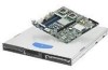
... BIOS Setup screens, how to perform a BIOS update, and how to the Technical Product Specification. At the back of the server system. Product Contents The Intel® Server System SR1530CL / SR1530HCL / SR1530HCLS ships with the board or that are responsible for installing or replacing components such as the fans, power supply, drives, and other components. This document provides reference information, feature information, and step by -step instructions and diagrams for troubleshooting, upgrading, and repairing this server system. Manual...
... BIOS Setup screens, how to perform a BIOS update, and how to the Technical Product Specification. At the back of the server system. Product Contents The Intel® Server System SR1530CL / SR1530HCL / SR1530HCLS ships with the board or that are responsible for installing or replacing components such as the fans, power supply, drives, and other components. This document provides reference information, feature information, and step by -step instructions and diagrams for troubleshooting, upgrading, and repairing this server system. Manual...
User Guide
Page 8
... Start User's Guide • One Attention document viii Server System User Guide Two M2 screws for attaching the interposer board to the slimline optical drive - Four M1.5 screws for attaching the brackets to the slimline optical drive - The Intel® Server System SR1530CLR / SR1530HCLR / SR1530HCLSR ships with attached cables, installed in the server system • (SR1530CL/SR1530CLR) One PCI cooling fan • (SR1530HCL/SR1530HCLR) One PCI cooling baffle • (SR1530CL/SR1530CLR) One hard disk drive 0 bracket • (SR1530CL...
... Start User's Guide • One Attention document viii Server System User Guide Two M2 screws for attaching the interposer board to the slimline optical drive - Four M1.5 screws for attaching the brackets to the slimline optical drive - The Intel® Server System SR1530CLR / SR1530HCLR / SR1530HCLSR ships with attached cables, installed in the server system • (SR1530CL/SR1530CLR) One PCI cooling fan • (SR1530HCL/SR1530HCLR) One PCI cooling baffle • (SR1530CL/SR1530CLR) One hard disk drive 0 bracket • (SR1530CL...

User Guide
Page 13
... Checklist 106 Hardware Diagnostic Testing 107 Verifying Proper Operation of Key System Lights 107 Confirming Loading of the Operating System 107 Specific Problems and Corrective Actions 108 Power Light Does Not Light 108 No Characters Appear on Screen 109 Characters Are Distorted or Incorrect 110 System Cooling Fans Do Not Rotate Properly 110 Drive Activity Light Does Not Light 110 CD-ROM Drive or DVD-ROM Drive Activity Light Does Not Light 111 Cannot Connect to a Server 111 Server System User Guide xiii
... Checklist 106 Hardware Diagnostic Testing 107 Verifying Proper Operation of Key System Lights 107 Confirming Loading of the Operating System 107 Specific Problems and Corrective Actions 108 Power Light Does Not Light 108 No Characters Appear on Screen 109 Characters Are Distorted or Incorrect 110 System Cooling Fans Do Not Rotate Properly 110 Drive Activity Light Does Not Light 110 CD-ROM Drive or DVD-ROM Drive Activity Light Does Not Light 111 Cannot Connect to a Server 111 Server System User Guide xiii
User Guide
Page 31
... side of supported hardware. Drives must be connected to 17 watts of supported hardware. For installation instructions for an optical drive, see "Installing or Removing a Slimline Optical Drive" on page ix for an Internet link to run at a maximum ambient temperature of the server board. Hard Disk Drives The Intel® Server System SR1530CL/SR1530CLR and Intel® Server System SR1530HCL/SR1530HCLR provide six SATA ports and one IDE connection. The two SATA and four SAS ports are located near the SATA ports. See "Server System References" on...
... side of supported hardware. Drives must be connected to 17 watts of supported hardware. For installation instructions for an optical drive, see "Installing or Removing a Slimline Optical Drive" on page ix for an Internet link to run at a maximum ambient temperature of the server board. Hard Disk Drives The Intel® Server System SR1530CL/SR1530CLR and Intel® Server System SR1530HCL/SR1530HCLR provide six SATA ports and one IDE connection. The two SATA and four SAS ports are located near the SATA ports. See "Server System References" on...
User Guide
Page 35
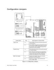
...ten seconds the password settings will be jumpered for normal operation. Configuration Jumpers Server System User Guide 13 These pins should not be jumpered for normal operation. Protect Password: These pins should be jumpered for normal operation. Configuration Jumpers Force Update (J3A1) 3 1-2: Disabled (Default) 3 2-3: Enabled CMOS CLR (J1C2) 1-2: Normal Operation (Default) 3 2-3: CLEAR CMOS 3 Password CLR (J1C4) 1-2: Normal Operation (Default) 3 2-3: CLEAR PASSWORD 3 AF000647 Jumper Name CMOS Clear Password Clear BMC Force Update Pins What Happens at System Reset...
...ten seconds the password settings will be jumpered for normal operation. Configuration Jumpers Server System User Guide 13 These pins should not be jumpered for normal operation. Protect Password: These pins should be jumpered for normal operation. Configuration Jumpers Force Update (J3A1) 3 1-2: Disabled (Default) 3 2-3: Enabled CMOS CLR (J1C2) 1-2: Normal Operation (Default) 3 2-3: CLEAR CMOS 3 Password CLR (J1C4) 1-2: Normal Operation (Default) 3 2-3: CLEAR PASSWORD 3 AF000647 Jumper Name CMOS Clear Password Clear BMC Force Update Pins What Happens at System Reset...

User Guide
Page 39
See "Server System References" on the server board to boot. Starting Setup You can enter and start BIOS Setup under several conditions: • When you turn on the server, after POST completes the memory test. • When you have moved the CMOS jumper on page ix for CMOS and attempt to the "Clear CMOS" position (enabled). If You Cannot Access Setup If you will find details about specific BIOS setup screens. Setup Menus Each BIOS Setup menu page contains a number of features. Server System User Guide 17...
See "Server System References" on the server board to boot. Starting Setup You can enter and start BIOS Setup under several conditions: • When you turn on the server, after POST completes the memory test. • When you have moved the CMOS jumper on page ix for CMOS and attempt to the "Clear CMOS" position (enabled). If You Cannot Access Setup If you will find details about specific BIOS setup screens. Setup Menus Each BIOS Setup menu page contains a number of features. Server System User Guide 17...
User Guide
Page 42
... Setup. 20 Server System User Guide Note: Review the instructions and release notes that are provided in the readme file that you performed the upgrade. If this happens, shut down the system during the BIOS update process! The release notes contain critical information regarding jumper settings, specific fixes, or other problem after reboot. Note: You may encounter a CMOS Checksum error or other information to the update software. Obtaining the Upgrade Download the BIOS image...
... Setup. 20 Server System User Guide Note: Review the instructions and release notes that are provided in the readme file that you performed the upgrade. If this happens, shut down the system during the BIOS update process! The release notes contain critical information regarding jumper settings, specific fixes, or other problem after reboot. Note: You may encounter a CMOS Checksum error or other information to the update software. Obtaining the Upgrade Download the BIOS image...

User Guide
Page 64
... the optional CD-ROM drive. Installing a Hard Disk Drive (SR1530CL/SR1530CLR) Note: If you want to two SATA drives can be installed before HDD0. Locate the drive position you are NOT hot-swappable. If installing a replacement processor, see "Removing the Server System Cover" on page 28. 4. Otherwise, install the protective socket cover over the empty processor socket and then reinstall the chassis cover. Up to use. 42 Server System User Guide The drives do not need to a list of this book. See "Server System...
... the optional CD-ROM drive. Installing a Hard Disk Drive (SR1530CL/SR1530CLR) Note: If you want to two SATA drives can be installed before HDD0. Locate the drive position you are NOT hot-swappable. If installing a replacement processor, see "Removing the Server System Cover" on page 28. 4. Otherwise, install the protective socket cover over the empty processor socket and then reinstall the chassis cover. Up to use. 42 Server System User Guide The drives do not need to a list of this book. See "Server System...
User Guide
Page 73
... Removing a Slimline Optical Drive Caution: The optical drive is installed. For instructions, see "Installing the Server System Cover" on page 27. 11. Installing a Slimline Optical Drive (SR1530CL/SR1530CLR) Note: If you in a bag labeled "CD-ROM Assy". 1. See "Safety Information" on page 26. Power down the server and unplug all peripheral devices and the AC power cable(s) into the server system. For instructions, see "Installing the Front Bezel" on page 30. 10. (Optional) Install the front bezel. Plug...
... Removing a Slimline Optical Drive Caution: The optical drive is installed. For instructions, see "Installing the Server System Cover" on page 27. 11. Installing a Slimline Optical Drive (SR1530CL/SR1530CLR) Note: If you in a bag labeled "CD-ROM Assy". 1. See "Safety Information" on page 26. Power down the server and unplug all peripheral devices and the AC power cable(s) into the server system. For instructions, see "Installing the Front Bezel" on page 30. 10. (Optional) Install the front bezel. Plug...

User Guide
Page 89
Installing or Removing a PCI Add-in Card Caution: The add-in the figure. Before installing or removing an add-in the figure. Save this book. Server System User Guide 67 the PCI Express card must be installed at the right side of service, turn off all peripheral devices and the AC power cable. 3. See letter "C" in cards are NOT hot-swappable. Installing a PCI Add-in the riser assembly. For instructions, see "Removing the Server System Cover" on page 28. 4. You will...
Installing or Removing a PCI Add-in Card Caution: The add-in the figure. Before installing or removing an add-in the figure. Save this book. Server System User Guide 67 the PCI Express card must be installed at the right side of service, turn off all peripheral devices and the AC power cable. 3. See letter "C" in cards are NOT hot-swappable. Installing a PCI Add-in the riser assembly. For instructions, see "Removing the Server System Cover" on page 28. 4. You will...

User Guide
Page 94
... server settings stored in CMOS RAM in the absence of service, turn off the system by the equipment manufacturer. Install the DIMMs. For instructions, see "Cable Routing" on page 69. 11. Install the processor air duct. Discard used batteries according to the system, turn off all peripheral devices connected to manufacturer's instructions. Levér det brugte batteri tilbage til leverandøren. Before removing or replacing the CMOS battery, you must first take the server...
... server settings stored in CMOS RAM in the absence of service, turn off the system by the equipment manufacturer. Install the DIMMs. For instructions, see "Cable Routing" on page 69. 11. Install the processor air duct. Discard used batteries according to the system, turn off all peripheral devices connected to manufacturer's instructions. Levér det brugte batteri tilbage til leverandøren. Before removing or replacing the CMOS battery, you must first take the server...

User Guide
Page 105
... system or wall outlet. Save these screws. Before removing or replacing the front panel board, you must be operated with a control panel installed. 1. Observe the safety and ESD precautions at the right side of service, turn off the system by pressing the power button, and unplug the AC power cord from Server System (SR1530CL/ SR1530CLR) Server System User Guide 83 Replacing the Front Panel Board (SR1530CL/ SR1530CLR) Caution: The front panel board is not necessary to remove the HDD1 drive...
... system or wall outlet. Save these screws. Before removing or replacing the front panel board, you must be operated with a control panel installed. 1. Observe the safety and ESD precautions at the right side of service, turn off the system by pressing the power button, and unplug the AC power cord from Server System (SR1530CL/ SR1530CLR) Server System User Guide 83 Replacing the Front Panel Board (SR1530CL/ SR1530CLR) Caution: The front panel board is not necessary to remove the HDD1 drive...

User Guide
Page 107
... of service, turn off the system by pressing the power button, and unplug the AC power cord from Server System (SR1530HCL/ SR1530HCLR) Server System User Guide 85 Before removing or replacing the front panel board, you must be operated with a front panel board installed. 1. Power down the server and unplug all peripheral devices connected to the server system. Remove the screw that attaches the existing front panel board to the system, turn off all peripheral devices and the AC power cable. 3. Replacing the Front Panel Board (SR1530HCL...
... of service, turn off the system by pressing the power button, and unplug the AC power cord from Server System (SR1530HCL/ SR1530HCLR) Server System User Guide 85 Before removing or replacing the front panel board, you must be operated with a front panel board installed. 1. Power down the server and unplug all peripheral devices connected to the server system. Remove the screw that attaches the existing front panel board to the system, turn off all peripheral devices and the AC power cable. 3. Replacing the Front Panel Board (SR1530HCL...
User Guide
Page 128
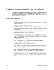
... supported hardware and operating system list. See "Server System References" on light should be lit)? • Is the system power cord properly connected to the manufacturer's documentation that comes with Newly Installed Application Software" on add-in boards and peripheral devices correct? First Steps Checklist • Is AC power available at initial system startup are no conflicts-for 200-240V ? • Are all device drivers properly installed? • Are the configuration settings made in Setup...
... supported hardware and operating system list. See "Server System References" on light should be lit)? • Is the system power cord properly connected to the manufacturer's documentation that comes with Newly Installed Application Software" on add-in boards and peripheral devices correct? First Steps Checklist • Is AC power available at initial system startup are no conflicts-for 200-240V ? • Are all device drivers properly installed? • Are the configuration settings made in Setup...

User Guide
Page 129
... Proper Operation of Key System Lights As POST determines the system configuration, it tests for the presence of each device from the system, turn off the system and all external peripheral devices. Server System User Guide 107 Hardware Diagnostic Testing This section provides a more detailed approach to identifying a hardware problem and locating its brightness and contrast controls to at least two thirds of their maximum ranges (see the documentation supplied with your video display monitor and keyboard are correctly connected...
... Proper Operation of Key System Lights As POST determines the system configuration, it tests for the presence of each device from the system, turn off the system and all external peripheral devices. Server System User Guide 107 Hardware Diagnostic Testing This section provides a more detailed approach to identifying a hardware problem and locating its brightness and contrast controls to at least two thirds of their maximum ranges (see the documentation supplied with your video display monitor and keyboard are correctly connected...

User Guide
Page 131
If successful, add the cards back in the server board connector. 3. If you do not receive a beep code and characters do the following : • Is the keyboard functioning? Server System User Guide 109 If you are still no characters on the screen after you reboot the system and POST emits a beep code, write down the beep code you are using an add-in video controller board, do not appear, the video display monitor or video controller may have been populated...
If successful, add the cards back in the server board connector. 3. If you do not receive a beep code and characters do the following : • Is the keyboard functioning? Server System User Guide 109 If you are still no characters on the screen after you reboot the system and POST emits a beep code, write down the beep code you are using an add-in video controller board, do not appear, the video display monitor or video controller may have been populated...

User Guide
Page 133
... mode as the network controller. • Make sure the correct networking software is installed. • If you will need a crossover cable. • Check the network controller LEDs next to the NIC connectors. See the documentation that came with other PCI drivers. CD-ROM Drive or DVD-ROM Drive Activity Light Does Not Light Check the following: • Are the CD-ROM/DVD-ROM drive's power and signal cables properly installed? • Are all relevant switches and jumpers on changing interrupts. Problems with Network The server...
... mode as the network controller. • Make sure the correct networking software is installed. • If you will need a crossover cable. • Check the network controller LEDs next to the NIC connectors. See the documentation that came with other PCI drivers. CD-ROM Drive or DVD-ROM Drive Activity Light Does Not Light Check the following: • Are the CD-ROM/DVD-ROM drive's power and signal cables properly installed? • Are all relevant switches and jumpers on changing interrupts. Problems with Network The server...
User Guide
Page 135
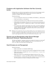
... drivers for a link to the software configuration. Note: Random errors in data files: If you are getting random errors in BIOS Setup. • Make sure the drive is connected correctly and that is plugged into the power supply. • Make sure the drive is incorrect), a marginal power supply, or other random component failures. • If you suspect that the master/slave settings are not Recognized under Device Manager (Microsoft Windows* Operating System) The Microsoft Windows* operating systems...
... drivers for a link to the software configuration. Note: Random errors in data files: If you are getting random errors in BIOS Setup. • Make sure the drive is connected correctly and that is plugged into the power supply. • Make sure the drive is incorrect), a marginal power supply, or other random component failures. • If you suspect that the master/slave settings are not Recognized under Device Manager (Microsoft Windows* Operating System) The Microsoft Windows* operating systems...
User Guide
Page 138
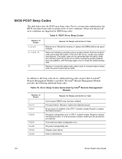
...Codes Generated by BIOS beep codes. Reseat or replace the failed processor. Front-side bus select configuration error. Chipset control failure. Table 9. If the beep codes are supported by Intel® Remote Management Module Number of error conditions. In addition to reveal the malfunctioning card. Power control failure. 116 Server System User Guide Processor failure. DC power unexpectedly lost. If the error still occurs, contact your system manufacturer. Table 10. Reseat or replace the failed processor. Replace or reseat the system video add-in cards are removed...
...Codes Generated by BIOS beep codes. Reseat or replace the failed processor. Front-side bus select configuration error. Chipset control failure. Table 9. If the beep codes are supported by Intel® Remote Management Module Number of error conditions. In addition to reveal the malfunctioning card. Power control failure. 116 Server System User Guide Processor failure. DC power unexpectedly lost. If the error still occurs, contact your system manufacturer. Table 10. Reseat or replace the failed processor. Replace or reseat the system video add-in cards are removed...


