
Product Guide
Page 3
... Safety Information 11 Intended Application Uses 11 Safety Instructions and Information 11 Checking the Power Cords 12 Multiple Power Cords...12 Earth Grounded Socket-Outlets 12 Before You Remove the Access Cover 13 Power Supply Modules 13 Fans ...13 Electrostatic Discharge (ESD 13 Cooling and Airflow...14 Lifting ...30 Installing Processors, Memory, Hard Disk Drives, and Options 31 Connecting the Monitor, Keyboard, and Mouse 32 Turning On the Server and Running the Power-On Self Test (POST 32 Hot Keys for POST ...33 Configuring the System with the FRU/SDR Load Utility 33 Installing ...
... Safety Information 11 Intended Application Uses 11 Safety Instructions and Information 11 Checking the Power Cords 12 Multiple Power Cords...12 Earth Grounded Socket-Outlets 12 Before You Remove the Access Cover 13 Power Supply Modules 13 Fans ...13 Electrostatic Discharge (ESD 13 Cooling and Airflow...14 Lifting ...30 Installing Processors, Memory, Hard Disk Drives, and Options 31 Connecting the Monitor, Keyboard, and Mouse 32 Turning On the Server and Running the Power-On Self Test (POST 32 Hot Keys for POST ...33 Configuring the System with the FRU/SDR Load Utility 33 Installing ...

Product Guide
Page 5
... Drive in a Carrier 86 Removing a Hot-swap Drive from a Carrier 87 Removing and Installing Hot-Swap Disk Drives 88 DC Power Supplies ...90 Checking the Power Status LEDs 90 Removing a Power Supply Module 91 Installing a Power Supply Module 92 PCI Add-In Boards ...93 Operating System Support for Hot-Plug Add-In Boards 93 Checking the Status... Drive 113 Installing a 5.25-inch Peripheral Drive 114 Hot Swap Drive Bays...115 Removing a Hot Swap Drive Bay 115 Installing a Hot-Swap Drive Bay 116 Power Distribution Board 117 Fan Distribution Board...118 Contents v
... Drive in a Carrier 86 Removing a Hot-swap Drive from a Carrier 87 Removing and Installing Hot-Swap Disk Drives 88 DC Power Supplies ...90 Checking the Power Status LEDs 90 Removing a Power Supply Module 91 Installing a Power Supply Module 92 PCI Add-In Boards ...93 Operating System Support for Hot-Plug Add-In Boards 93 Checking the Status... Drive 113 Installing a 5.25-inch Peripheral Drive 114 Hot Swap Drive Bays...115 Removing a Hot Swap Drive Bay 115 Installing a Hot-Swap Drive Bay 116 Power Distribution Board 117 Fan Distribution Board...118 Contents v

Product Guide
Page 6
...Proper Operation of Key System Lights 123 Confirming Loading of an Operating System 123 Specific Problems and Corrective Actions 123 Power Light Does Not Light 123 No Beep Codes ...124 No Characters Appear on Screen 124 Characters Are Distorted or ... Power Supplies ...136 System Cooling ...136 Server Board Set Features 137 Baseboard Connector and Component Locations 138 Baseboard Jumpers...139 Processors ...141 DIMM Memory ...141 Onboard Video ...141 SCSI Controller...141 Network Interface Controllers 142 Network Teaming Features 143 ACPI ...145 vi Intel SPSH4 Server Platform ...
...Proper Operation of Key System Lights 123 Confirming Loading of an Operating System 123 Specific Problems and Corrective Actions 123 Power Light Does Not Light 123 No Beep Codes ...124 No Characters Appear on Screen 124 Characters Are Distorted or ... Power Supplies ...136 System Cooling ...136 Server Board Set Features 137 Baseboard Connector and Component Locations 138 Baseboard Jumpers...139 Processors ...141 DIMM Memory ...141 Onboard Video ...141 SCSI Controller...141 Network Interface Controllers 142 Network Teaming Features 143 ACPI ...145 vi Intel SPSH4 Server Platform ...

Product Guide
Page 7
...Server (Rack-Mount and Pedestal 29 2. Removing the Rear Access Cover 66 4. Installing the Memory Board 70 8. Installing Processors 79 17. Installing the Heat Sink 80 18. Removing a Processor 81 19. Installing Memory ...83 20. Removing DIMMs ...84 21. Removing a Drive Carrier 88 25. Immunity 147 Power... Mechanism 75 13. Hot-Swap SCSI Drive Bay and Status Indicators 85 22. Installing a Drive Carrier 89 26. Removing a Power Supply Module 91 28. Removing the Processor Board Air Baffle 71 9. Correct Order for Populating Processor Sockets 78 15. Removing a Plastic...
...Server (Rack-Mount and Pedestal 29 2. Removing the Rear Access Cover 66 4. Installing the Memory Board 70 8. Installing Processors 79 17. Installing the Heat Sink 80 18. Removing a Processor 81 19. Installing Memory ...83 20. Removing DIMMs ...84 21. Removing a Drive Carrier 88 25. Immunity 147 Power... Mechanism 75 13. Hot-Swap SCSI Drive Bay and Status Indicators 85 22. Installing a Drive Carrier 89 26. Removing a Power Supply Module 91 28. Removing the Processor Board Air Baffle 71 9. Correct Order for Populating Processor Sockets 78 15. Removing a Plastic...

Product Guide
Page 8
... Removing and Installing a Fan Module 100 35. Installing the Front Subchassis and Rear Electronics Bay 104 38. SPSH4 Server Hot-Swap Access 130 53. SPSH4 Server Physical Specifications 30 3. LED States for Hot-Plug PCI Add-In Boards 94 30. Rear Cables in the ... Compliance Markings 148 viii Intel SPSH4 Server Platform Product Guide Front Cables in the Cable Clamp 108 42. Feature Summary...129 11. Replacing the Diskette Drive 110 44. Removing a Hot Swap Drive Bay 115 48. Baseboard Jumpers 139 Tables 1. LED Power Supply Status Indicators 90 9. Replacing...
... Removing and Installing a Fan Module 100 35. Installing the Front Subchassis and Rear Electronics Bay 104 38. SPSH4 Server Hot-Swap Access 130 53. SPSH4 Server Physical Specifications 30 3. LED States for Hot-Plug PCI Add-In Boards 94 30. Rear Cables in the ... Compliance Markings 148 viii Intel SPSH4 Server Platform Product Guide Front Cables in the Cable Clamp 108 42. Feature Summary...129 11. Replacing the Diskette Drive 110 44. Removing a Hot Swap Drive Bay 115 48. Baseboard Jumpers 139 Tables 1. LED Power Supply Status Indicators 90 9. Replacing...

Product Guide
Page 12
... before accessing inside the system. Apparaten skall anslutas till jordat uttag när den ansluts till ett nätverk. 12 Intel SPSH4 Server Platform Product Guide The power supply cord(s) is the main disconnect device to modify or use in your region, and shall be marked with a suitable earth ground.... rating that is provided with the certification markings. • The power cord plug cap that plugs into the AC receptacle on the power supply must be an IEC 320, sheet C13, type female connector. • In Europe, the power cord must be less than 4.5 meters (14.76 feet) long...
... before accessing inside the system. Apparaten skall anslutas till jordat uttag när den ansluts till ett nätverk. 12 Intel SPSH4 Server Platform Product Guide The power supply cord(s) is the main disconnect device to modify or use in your region, and shall be marked with a suitable earth ground.... rating that is provided with the certification markings. • The power cord plug cap that plugs into the AC receptacle on the power supply must be an IEC 320, sheet C13, type female connector. • In Europe, the power cord must be less than 4.5 meters (14.76 feet) long...

Product Guide
Page 13
... on the front of the product. • Disconnect the AC power by the edges. • Place the server components on the server chassis before touching the server components. • Keep part of your body in the power supply. Power Supply Modules CAUTION Power supply modules have double-pole/neutral fusing. There are connected to the system. • Retain all peripheral...
... on the front of the product. • Disconnect the AC power by the edges. • Place the server components on the server chassis before touching the server components. • Keep part of your body in the power supply. Power Supply Modules CAUTION Power supply modules have double-pole/neutral fusing. There are connected to the system. • Retain all peripheral...

Product Guide
Page 14
... consult your local regional electrical codes. The equipment rack must be installed according to your local approved electrician. 14 Intel SPSH4 Server Platform Product Guide MAIN AC POWER DISCONNECT You are fully extended out of any other devices installed in place can cause overheating and damage to have ... the rack assembly. Cooling and Airflow CAUTION For proper cooling and airflow, always install all access covers before turning on the power supplies. Lifting and Moving CAUTION Do not attempt to prevent the rack from falling over when one or more systems are responsible for...
... consult your local regional electrical codes. The equipment rack must be installed according to your local approved electrician. 14 Intel SPSH4 Server Platform Product Guide MAIN AC POWER DISCONNECT You are fully extended out of any other devices installed in place can cause overheating and damage to have ... the rack assembly. Cooling and Airflow CAUTION For proper cooling and airflow, always install all access covers before turning on the power supplies. Lifting and Moving CAUTION Do not attempt to prevent the rack from falling over when one or more systems are responsible for...
Product Guide
Page 16
... connectors or ports on the back of the system if a padlock has been installed. 2. continued 16 Intel SPSH4 Server Platform Product Guide WARNING: English (US) The power supply in this : 1. The power cord(s) is not the exact type required. To do this product contains no user-serviceable parts. Check...shall be installed near the equipment and shall be more than one power supply will have a separate AC power cord for each AC power cord from the covers. 3. Unplug all screws from the wall outlet or power supply. Unlock and remove the padlock from wall outlets. 4. Operating ...
... connectors or ports on the back of the system if a padlock has been installed. 2. continued 16 Intel SPSH4 Server Platform Product Guide WARNING: English (US) The power supply in this : 1. The power cord(s) is not the exact type required. To do this product contains no user-serviceable parts. Check...shall be installed near the equipment and shall be more than one power supply will have a separate AC power cord for each AC power cord from the covers. 3. Unplug all screws from the wall outlet or power supply. Unlock and remove the padlock from wall outlets. 4. Operating ...

Product Guide
Page 17
... are susceptible to electrical storms, we recommend you plug your system into a surge suppresser and disconnect telecommunication lines to access the power supply cord(s), because they serve as the product's main power disconnect. WARNING: English (US) (Continued) A microprocessor and heat sink may be hot if the system has been running. Contact should be...
... are susceptible to electrical storms, we recommend you plug your system into a surge suppresser and disconnect telecommunication lines to access the power supply cord(s), because they serve as the product's main power disconnect. WARNING: English (US) (Continued) A microprocessor and heat sink may be hot if the system has been running. Contact should be...
Product Guide
Page 27
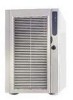
...8226; Intel® SPSH4 Server Platform with the following parts installed: SSH4 baseboard SSH4 processor board SSH4 memory board Fan distribution board Front panel board Hot plug indicator board Power distribution board Two 600-W power supplies &#... parts. • Quick Start Guide (fold-out poster) • System Accessory Kit Two North American power cords SPSH4 Server Platform System Resource CD (contains product documentation, device drivers, and software utilities) Three sets (six rails) 5....
...8226; Intel® SPSH4 Server Platform with the following parts installed: SSH4 baseboard SSH4 processor board SSH4 memory board Fan distribution board Front panel board Hot plug indicator board Power distribution board Two 600-W power supplies &#... parts. • Quick Start Guide (fold-out poster) • System Accessory Kit Two North American power cords SPSH4 Server Platform System Resource CD (contains product documentation, device drivers, and software utilities) Three sets (six rails) 5....

Product Guide
Page 30
Table 2. SPSH4 Server Physical Specifications Specification Rack Mount Height 12.25 inches (311 mm) (7U) Width Fits 19-inch rack Depth 25.25 inches (641 mm) Weight Minimum configuration 90 pounds (41 kg) Maximum configuration 119 pounds (57 kg) Required front clearance 3 inches (76 mm), inlet airflow
Table 2. SPSH4 Server Physical Specifications Specification Rack Mount Height 12.25 inches (311 mm) (7U) Width Fits 19-inch rack Depth 25.25 inches (641 mm) Weight Minimum configuration 90 pounds (41 kg) Maximum configuration 119 pounds (57 kg) Required front clearance 3 inches (76 mm), inlet airflow

Product Guide
Page 31
...page 85. 8. Installing hard disk drives-see page 70. 6. Installing Processors, Memory, Hard Disk Drives, and Options The server is included with the server. b. Getting Started 31 b. Installing memory and processors: a. Installing the processor and memory boards: a. Installing covers: a.... geographic regions that are susceptible to electrical storms, Intel strongly recommends that came with the ICMB board kit. 5. Installing the processors on the guide, see page 69. Installing an additional power supply or additional peripherals-see page 74. Installing the...
...page 85. 8. Installing hard disk drives-see page 70. 6. Installing Processors, Memory, Hard Disk Drives, and Options The server is included with the server. b. Getting Started 31 b. Installing memory and processors: a. Installing the processor and memory boards: a. Installing covers: a.... geographic regions that are susceptible to electrical storms, Intel strongly recommends that came with the ICMB board kit. 5. Installing the processors on the guide, see page 69. Installing an additional power supply or additional peripherals-see page 74. Installing the...

Product Guide
Page 33
...can use during POST. Enter the Adaptec SCSISelect Utility during POST. * Boot to change the boot device, the change the number of the server, false errors might be generated by sensors that don't actually exist, and sensors that is updating memory size on screen. Table 3. Note:...that do exist might not be monitored. is displayed. If the FRU/SDR configuration does not match the physical configuration of processors, fans, or power supplies, you must run the FRU/SDR Load Utility to monitor temperature, voltage, and other parameters. ✏ NOTE If there is no device ...
...can use during POST. Enter the Adaptec SCSISelect Utility during POST. * Boot to change the boot device, the change the number of the server, false errors might be generated by sensors that don't actually exist, and sensors that is updating memory size on screen. Table 3. Note:...that do exist might not be monitored. is displayed. If the FRU/SDR configuration does not match the physical configuration of processors, fans, or power supplies, you must run the FRU/SDR Load Utility to monitor temperature, voltage, and other parameters. ✏ NOTE If there is no device ...

Product Guide
Page 47
... chassis intrusion sensors. • Manages nonvolatile storage for system management activities. Processor Sockets Temperature Sensors Power Supplies Fans Chassis Intrusion Memory BMC Nonvolatile storage SEL SDR FRU Front Panel EMP LAN1 Figure 2. Integrated System Management Baseboard Management Controller Intel server boards incorporate a baseboard management controller (BMC), which is a simplified diagram of the system management...
... chassis intrusion sensors. • Manages nonvolatile storage for system management activities. Processor Sockets Temperature Sensors Power Supplies Fans Chassis Intrusion Memory BMC Nonvolatile storage SEL SDR FRU Front Panel EMP LAN1 Figure 2. Integrated System Management Baseboard Management Controller Intel server boards incorporate a baseboard management controller (BMC), which is a simplified diagram of the system management...
Product Guide
Page 48
... completes the system configuration. Such events include temperatures and voltages out of range • Fan failure • Chassis intrusion • Power supply fault • BIOS uncorrectable ECC error • BIOS POST error • Processor fault resilient booting (FRB) failure • Fatal...Events can trigger alerts and other than the front panel switch • Watchdog timer reset, power down, or power cycle • System restart (reboot) 48 Intel SPSH4 Server Platform Product Guide Field Replaceable Units and Sensor Data Records Field replaceable units (FRUs) are shipped ...
... completes the system configuration. Such events include temperatures and voltages out of range • Fan failure • Chassis intrusion • Power supply fault • BIOS uncorrectable ECC error • BIOS POST error • Processor fault resilient booting (FRB) failure • Fatal...Events can trigger alerts and other than the front panel switch • Watchdog timer reset, power down, or power cycle • System restart (reboot) 48 Intel SPSH4 Server Platform Product Guide Field Replaceable Units and Sensor Data Records Field replaceable units (FRUs) are shipped ...

Product Guide
Page 62
... Record (SDR) load utility is FRUSDR.EXE. The executable file for the utility is a DOS-based program used to update the server management subsystem's product level FRU and SDR nonvolatile storage. The utility requires the following: • ROM-DOS version 6.22 or MS... file describing the sensors in BMC nonvolatile storage does not match the physical configuration of power supplies, processors, or fans in the server • When installing a FRU/SDR update (page 45) ✏ NOTE If the FRU/SDR configuration information in the system 62 Intel SPSH4 Server Platform Product Guide
... Record (SDR) load utility is FRUSDR.EXE. The executable file for the utility is a DOS-based program used to update the server management subsystem's product level FRU and SDR nonvolatile storage. The utility requires the following: • ROM-DOS version 6.22 or MS... file describing the sensors in BMC nonvolatile storage does not match the physical configuration of power supplies, processors, or fans in the server • When installing a FRU/SDR update (page 45) ✏ NOTE If the FRU/SDR configuration information in the system 62 Intel SPSH4 Server Platform Product Guide

Product Guide
Page 66
...cover, check that the cover tabs align with the captive fasteners located on the rear edge of the chassis. 3. Attach the cover to the power supply bay. To install the rear access cover: 1. To remove the cover: 1. While lightly pressing the cover against the chassis, slide it ... the cover away from the chassis. While lightly pressing the cover against the chassis, slide it toward the rear of the cover. 66 Intel SPSH4 Server Platform Product Guide Position the cover on the rear edge of the chassis until the cover tabs fully engage the chassis slots. 3. Release the ...
...cover, check that the cover tabs align with the captive fasteners located on the rear edge of the chassis. 3. Attach the cover to the power supply bay. To install the rear access cover: 1. To remove the cover: 1. While lightly pressing the cover against the chassis, slide it ... the cover away from the chassis. While lightly pressing the cover against the chassis, slide it toward the rear of the cover. 66 Intel SPSH4 Server Platform Product Guide Position the cover on the rear edge of the chassis until the cover tabs fully engage the chassis slots. 3. Release the ...

Product Guide
Page 90
... baseboard and other components, but the server still won't power on, replace the power distribution board (page 117). 90 Intel SPSH4 Server Platform Product Guide fan performance problem. ✏ NOTE If all power supply modules are functioning and all power cables from the power supply modules. DC Power Supplies The power supply bay accommodates up to this power supply. Blinking Off Off AC power present, standby outputs on , DC...
... baseboard and other components, but the server still won't power on, replace the power distribution board (page 117). 90 Intel SPSH4 Server Platform Product Guide fan performance problem. ✏ NOTE If all power supply modules are functioning and all power cables from the power supply modules. DC Power Supplies The power supply bay accommodates up to this power supply. Blinking Off Off AC power present, standby outputs on , DC...

Product Guide
Page 91
... will feel. Installing and Removing Components 91 Use even, steady force to release the power supply module and carefully pull the module out of the power supply bay. 4. The module disengaging from the power supply. 5. Removing a Power Supply Module To remove a power supply module: 1. Disconnect the AC power cord for the supply from the power supply bay. Pull the latch handle to remove the...
... will feel. Installing and Removing Components 91 Use even, steady force to release the power supply module and carefully pull the module out of the power supply bay. 4. The module disengaging from the power supply. 5. Removing a Power Supply Module To remove a power supply module: 1. Disconnect the AC power cord for the supply from the power supply bay. Pull the latch handle to remove the...
