
Product Guide
Page 3
... Getting Started Selecting a Site ...29 Space and Power Requirements 29 General Site Criteria ...30 Installing Processors, Memory, Hard Disk Drives, and Options 31 Connecting the Monitor, Keyboard, and Mouse 32 Turning On the Server and Running the Power-On Self Test (POST 32 Hot Keys for POST ...33 Configuring the System... 34 Installing the Operating System 34 The System Resource CD-ROM 34 System Security ...35 Mechanical Locks ...35 Software Security ...36 Installing the Server in a Rack 37 4 Configuration Software and Utilities BIOS Setup ...39 Recording BIOS Setup Settings 39 iii
... Getting Started Selecting a Site ...29 Space and Power Requirements 29 General Site Criteria ...30 Installing Processors, Memory, Hard Disk Drives, and Options 31 Connecting the Monitor, Keyboard, and Mouse 32 Turning On the Server and Running the Power-On Self Test (POST 32 Hot Keys for POST ...33 Configuring the System... 34 Installing the Operating System 34 The System Resource CD-ROM 34 System Security ...35 Mechanical Locks ...35 Software Security ...36 Installing the Server in a Rack 37 4 Configuration Software and Utilities BIOS Setup ...39 Recording BIOS Setup Settings 39 iii
Product Guide
Page 4
... Hardware System Management 47 Baseboard Management Controller 47 Field Replaceable Units and Sensor Data Records 48 System Event Log ...48 Platform Event Management 48 Emergency Management Port 49 Intel Server Management ...49 Using the System Setup Utility 50 Creating SSU Diskettes 50 Running the SSU...51 Setting Boot Device Priority... 68 Installing the Access Cover to the System Boards 68 Removing the Memory Board 69 Installing the Memory Board 70 Removing the Processor Board Air Baffle 71 Installing the Processor Board Air Baffle 72 iv Intel SPSH4 Server Platform Product Guide
... Hardware System Management 47 Baseboard Management Controller 47 Field Replaceable Units and Sensor Data Records 48 System Event Log ...48 Platform Event Management 48 Emergency Management Port 49 Intel Server Management ...49 Using the System Setup Utility 50 Creating SSU Diskettes 50 Running the SSU...51 Setting Boot Device Priority... 68 Installing the Access Cover to the System Boards 68 Removing the Memory Board 69 Installing the Memory Board 70 Removing the Processor Board Air Baffle 71 Installing the Processor Board Air Baffle 72 iv Intel SPSH4 Server Platform Product Guide

Product Guide
Page 5
... 74 Removing the Baseboard 75 Installing the Baseboard 77 Processors ...78 Installing Processors...78 Removing Processors...81 Memory ...82 Installing DIMMs ...82 Removing DIMMs ...84 Hot-Swap SCSI Drives ...85 Checking a Hot-Swap SCSI Drive Status Indicator 85 Installing a Hot-Swap ...
... 74 Removing the Baseboard 75 Installing the Baseboard 77 Processors ...78 Installing Processors...78 Removing Processors...81 Memory ...82 Installing DIMMs ...82 Removing DIMMs ...84 Hot-Swap SCSI Drives ...85 Checking a Hot-Swap SCSI Drive Status Indicator 85 Installing a Hot-Swap ...

Product Guide
Page 6
... Problems ...126 PCI Installation Tips...127 Problems with Application Software 127 Bootable CD-ROM Is Not Detected 127 A Server Description Feature Summary...129 Chassis Access ...130 Main Chassis Components 131 Electronics Bay Components 132 Front Control Panel ...133... Cooling ...136 Server Board Set Features 137 Baseboard Connector and Component Locations 138 Baseboard Jumpers...139 Processors ...141 DIMM Memory ...141 Onboard Video ...141 SCSI Controller...141 Network Interface Controllers 142 Network Teaming Features 143 ACPI ...145 vi Intel SPSH4 Server Platform Product Guide
... Problems ...126 PCI Installation Tips...127 Problems with Application Software 127 Bootable CD-ROM Is Not Detected 127 A Server Description Feature Summary...129 Chassis Access ...130 Main Chassis Components 131 Electronics Bay Components 132 Front Control Panel ...133... Cooling ...136 Server Board Set Features 137 Baseboard Connector and Component Locations 138 Baseboard Jumpers...139 Processors ...141 DIMM Memory ...141 Onboard Video ...141 SCSI Controller...141 Network Interface Controllers 142 Network Teaming Features 143 ACPI ...145 vi Intel SPSH4 Server Platform Product Guide

Product Guide
Page 7
... 90 27. Integrated System Management 47 3. Removing the Access Cover to the System Boards 68 6. Removing a Processor 81 19. Removing DIMMs ...84 21. Removing the Processor Board Air Baffle 71 9. Removing the Front Retention Mechanism 75 13. Baseboard Mounting 76 14. Installing Memory ......83 20. Raising the Locking Bar 79 16. Installing a Drive Carrier 89 26. PCI Add-In Board Locations 93 Contents vii PSH4 Server (Rack-Mount...
... 90 27. Integrated System Management 47 3. Removing the Access Cover to the System Boards 68 6. Removing a Processor 81 19. Removing DIMMs ...84 21. Removing the Processor Board Air Baffle 71 9. Removing the Front Retention Mechanism 75 13. Baseboard Mounting 76 14. Installing Memory ......83 20. Raising the Locking Bar 79 16. Installing a Drive Carrier 89 26. PCI Add-In Board Locations 93 Contents vii PSH4 Server (Rack-Mount...
Product Guide
Page 27
...• Quick Start Guide (fold-out poster) • System Accessory Kit Two North American power cords SPSH4 Server Platform System Resource CD (contains product documentation, device drivers, and software utilities) Three sets (six rails) 5.25-inch ...Inspecting Checking for Damage to package the server for evidence of the contents appear damaged, file a damage claim with the carrier immediately. • Intel® SPSH4 Server Platform with the following parts installed: SSH4 baseboard SSH4 processor board SSH4 memory board ...
...• Quick Start Guide (fold-out poster) • System Accessory Kit Two North American power cords SPSH4 Server Platform System Resource CD (contains product documentation, device drivers, and software utilities) Three sets (six rails) 5.25-inch ...Inspecting Checking for Damage to package the server for evidence of the contents appear damaged, file a damage claim with the carrier immediately. • Intel® SPSH4 Server Platform with the following parts installed: SSH4 baseboard SSH4 processor board SSH4 memory board ...

Product Guide
Page 29
... (optional). 7. SPSH4 Server (Rack-Mount and Pedestal) 29 Space and Power Requirements The server is available in both rack-mount and pedestal versions. Configure the system with the FRU/SDR load utility. 6. Selecting a Site This section describes the space and power requirements and general site criteria for installing the server. OM13380 Figure 1. Install processors, memory...
... (optional). 7. SPSH4 Server (Rack-Mount and Pedestal) 29 Space and Power Requirements The server is available in both rack-mount and pedestal versions. Configure the system with the FRU/SDR load utility. 6. Selecting a Site This section describes the space and power requirements and general site criteria for installing the server. OM13380 Figure 1. Install processors, memory...

Product Guide
Page 31
..., Hard Disk Drives, and Options The server is included with the server. Removing the access cover to the system boards-see the references below: 1. Removing the memory board-see page 66. b. Installing the processors on the guide, see page 68. Installing covers...9999; NOTES Surge suppressor recommended: In geographic regions that are susceptible to electrical storms, Intel strongly recommends that is shipped without processors, memory, or hard drives. To install the memory, processors, hard drives, and other options, follow the instructions that came with the peripherals. 9....
..., Hard Disk Drives, and Options The server is included with the server. Removing the access cover to the system boards-see the references below: 1. Removing the memory board-see page 66. b. Installing the processors on the guide, see page 68. Installing covers...9999; NOTES Surge suppressor recommended: In geographic regions that are susceptible to electrical storms, Intel strongly recommends that is shipped without processors, memory, or hard drives. To install the memory, processors, hard drives, and other options, follow the instructions that came with the peripherals. 9....

Product Guide
Page 32
Insert the SPSH4 Server Platform System Resource CD into the power source or wall outlet. To start the server, the Power-On Self Test (POST) runs automatically. For a summary of hot keys active during POST. POST discovers, configures, and tests the processors, memory, keyboard, and most installed peripheral ...press specific keys at the bottom of time needed to complete POST depends on the System Resource CD. 32 Intel SPSH4 Server Platform Product Guide If you enter BIOS Setup, the Service Partition, or the Adaptec† SCSISelect† Utility, when you start the...
Insert the SPSH4 Server Platform System Resource CD into the power source or wall outlet. To start the server, the Power-On Self Test (POST) runs automatically. For a summary of hot keys active during POST. POST discovers, configures, and tests the processors, memory, keyboard, and most installed peripheral ...press specific keys at the bottom of time needed to complete POST depends on the System Resource CD. 32 Intel SPSH4 Server Platform Product Guide If you enter BIOS Setup, the Service Partition, or the Adaptec† SCSISelect† Utility, when you start the...

Product Guide
Page 33
... the current boot only. is updating memory size on screen. Enter the Adaptec SCSISelect Utility during POST and display a menu for the server. Configuring the System with the FRU/SDR Load Utility After POST completes and the system has finished booting from a network using Preboot Execution... * Environment (PXE). Hot Keys for POST Table 3 lists the hot keys you use during POST to make sure your server and any of processors, fans, or power supplies, you have a device with a bootable operating system but see this message anyway, reboot and use BIOS Setup...
... the current boot only. is updating memory size on screen. Enter the Adaptec SCSISelect Utility during POST and display a menu for the server. Configuring the System with the FRU/SDR Load Utility After POST completes and the system has finished booting from a network using Preboot Execution... * Environment (PXE). Hot Keys for POST Table 3 lists the hot keys you use during POST to make sure your server and any of processors, fans, or power supplies, you have a device with a bootable operating system but see this message anyway, reboot and use BIOS Setup...

Product Guide
Page 47
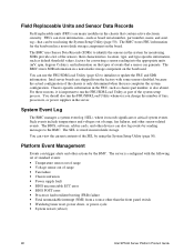
... the hardware and provides additional features through Intel Server Management software. 5 System Management Intel integrates system management features into the server. Integrated Hardware System Management Figure 2 is... a dedicated microcontroller for the system event log (SEL), sensor data records (SDRs), and baseboard field-replaceable unit (FRU) inventory. • Interfaces with the emergency management port (EMP) and LAN1 port to configure the hardware features. Processor...
... the hardware and provides additional features through Intel Server Management software. 5 System Management Intel integrates system management features into the server. Integrated Hardware System Management Figure 2 is... a dedicated microcontroller for the system event log (SEL), sensor data records (SDRs), and baseboard field-replaceable unit (FRU) inventory. • Interfaces with the emergency management port (EMP) and LAN1 port to configure the hardware features. Processor...
Product Guide
Page 48
...than the front panel switch • Watchdog timer reset, power down, or power cycle • System restart (reboot) 48 Intel SPSH4 Server Platform Product Guide The server is configured with some sensors disabled, because the actual configuration of the chassis is important to identify the sensors in cards, ...). The BMC uses Sensor Data Records (SDRs) to run the FRU/SDR Load Utility whenever you change the number of fans, processors, or power supplies in the chassis that contain active electronic circuitry. Chassis-specific information in nonvolatile storage. The SEL is also absent...
...than the front panel switch • Watchdog timer reset, power down, or power cycle • System restart (reboot) 48 Intel SPSH4 Server Platform Product Guide The server is configured with some sensors disabled, because the actual configuration of the chassis is important to identify the sensors in cards, ...). The BMC uses Sensor Data Records (SDRs) to run the FRU/SDR Load Utility whenever you change the number of fans, processors, or power supplies in the chassis that contain active electronic circuitry. Chassis-specific information in nonvolatile storage. The SEL is also absent...

Product Guide
Page 62
...product configuration based on instructions in BMC nonvolatile storage does not match the physical configuration of the server, you should run the updated version from the Utilities menu of power supplies, processors, or fans in the server • When installing a FRU/SDR update (page 45) ✏ NOTE If the ... do exist might not be monitored. Running the FRU/SDR Load Utility You can run the FRU/SDR utility in the system 62 Intel SPSH4 Server Platform Product Guide However, if you have downloaded an update, you might see false errors generated by the BMC that holds the SDR and...
...product configuration based on instructions in BMC nonvolatile storage does not match the physical configuration of the server, you should run the updated version from the Utilities menu of power supplies, processors, or fans in the server • When installing a FRU/SDR update (page 45) ✏ NOTE If the ... do exist might not be monitored. Running the FRU/SDR Load Utility You can run the FRU/SDR utility in the system 62 Intel SPSH4 Server Platform Product Guide However, if you have downloaded an update, you might see false errors generated by the BMC that holds the SDR and...
Product Guide
Page 65
Access Covers This section includes instructions for processor heat sink clips: Dexter Design (503) 648-7000 [email protected] Order part number: 650308-003-P6 • Antistatic wrist strap and conductive foam pad (... log (page 161) As you integrate new parts into the system, record the model and serial number of the server system, all installed options, and any other pertinent information specific to the server system. 6 Installing and Removing Components Tools and Supplies Needed • Phillips† screwdriver • Small flat-bladed screwdriver •...
Access Covers This section includes instructions for processor heat sink clips: Dexter Design (503) 648-7000 [email protected] Order part number: 650308-003-P6 • Antistatic wrist strap and conductive foam pad (... log (page 161) As you integrate new parts into the system, record the model and serial number of the server system, all installed options, and any other pertinent information specific to the server system. 6 Installing and Removing Components Tools and Supplies Needed • Phillips† screwdriver • Small flat-bladed screwdriver •...

Product Guide
Page 68
Lift the end of the server. 2. Press down gently and tighten the captive screws at the rear of the chassis. 3. Removing the Access Cover to the System Boards Installing the Access ... processor board air baffle • Removing and installing the processor board • Removing and installing the baseboard Removing the Access Cover to the System Boards To remove the access cover to the System Boards To install the access cover: 1. Loosen the two captive screws located at the front of the cover. 68 Intel SPSH4 Server Platform...
Lift the end of the server. 2. Press down gently and tighten the captive screws at the rear of the chassis. 3. Removing the Access Cover to the System Boards Installing the Access ... processor board air baffle • Removing and installing the processor board • Removing and installing the baseboard Removing the Access Cover to the System Boards To remove the access cover to the System Boards To install the access cover: 1. Loosen the two captive screws located at the front of the cover. 68 Intel SPSH4 Server Platform...

Product Guide
Page 69
OM13385 Figure 6. Grasp the bracket on the processor board (Figure 6). 2. Removing the Memory Board Installing and Removing Components 69 Removing the Memory Board To remove the memory board: 1. Lift the memory board out of the memory board and pull straight up until the board disengages from the connector on the top edge of the chassis.
OM13385 Figure 6. Grasp the bracket on the processor board (Figure 6). 2. Removing the Memory Board Installing and Removing Components 69 Removing the Memory Board To remove the memory board: 1. Lift the memory board out of the memory board and pull straight up until the board disengages from the connector on the top edge of the chassis.

Product Guide
Page 70
Installing the Memory Board 70 Intel SPSH4 Server Platform Product Guide OM13386 Figure 7. Align the memory board with the connector on the processor board and press down on the top edge of the electronics bay. 2. Holding the bracket on the bracket until the board is fully inserted into the guides at both ends of the memory board, insert the board into the connector. Installing the Memory Board To install the memory board: 1.
Installing the Memory Board 70 Intel SPSH4 Server Platform Product Guide OM13386 Figure 7. Align the memory board with the connector on the processor board and press down on the top edge of the electronics bay. 2. Holding the bracket on the bracket until the board is fully inserted into the guides at both ends of the memory board, insert the board into the connector. Installing the Memory Board To install the memory board: 1.

Product Guide
Page 71
A OM13387 Figure 8. Removing the Processor Board Air Baffle Installing and Removing Components 71 Removing the Processor Board Air Baffle To remove the processor board air baffle: 1. At the end of the air baffle closest to the rear of the electronics bay and remove the baffle from the chassis. Disengage the air baffle at the front of the chassis, press the two tabs toward each other (Figure 8, A) and raise the end, rotating the baffle about 30°. 2.
A OM13387 Figure 8. Removing the Processor Board Air Baffle Installing and Removing Components 71 Removing the Processor Board Air Baffle To remove the processor board air baffle: 1. At the end of the air baffle closest to the rear of the electronics bay and remove the baffle from the chassis. Disengage the air baffle at the front of the chassis, press the two tabs toward each other (Figure 8, A) and raise the end, rotating the baffle about 30°. 2.

Product Guide
Page 72
... Air Baffle To install the processor board air baffle: 1. Holding the baffle at an angle of the baffle until it down . Adjust the position of about 30° will allow the ... baffle raised, insert the tab on the front of the baffle down . Do not force it moves into the slot in the chassis. Installing the Processor Board Air Baffle 72 Intel SPSH4 Server Platform Product Guide Orient the baffle so that the two release tabs are engaged.
... Air Baffle To install the processor board air baffle: 1. Holding the baffle at an angle of the baffle until it down . Adjust the position of about 30° will allow the ... baffle raised, insert the tab on the front of the baffle down . Do not force it moves into the slot in the chassis. Installing the Processor Board Air Baffle 72 Intel SPSH4 Server Platform Product Guide Orient the baffle so that the two release tabs are engaged.

Product Guide
Page 73
Using the handles, tilt the processor board up and remove it from the chassis. OM13389 Figure 10. Rotate the handles on the processor board until they are fully open (Figure 10). 2. Removing the Processor Board Installing and Removing Components 73 Removing the Processor Board To remove the processor board: 1.
Using the handles, tilt the processor board up and remove it from the chassis. OM13389 Figure 10. Rotate the handles on the processor board until they are fully open (Figure 10). 2. Removing the Processor Board Installing and Removing Components 73 Removing the Processor Board To remove the processor board: 1.