
Product Specification
Page 3
... x8 ...33 5.1.4 PCI Express x16 (E7525 MCH support only 33 5.2 Video Controller ...34 5.2.1 Video Modes...34 5.2.2 Video Memory Interface 35 5.2.3 Host Bus Interface 35 5.3 Network Interface Controller (NIC 36 5.3.1 NIC Connector and Status LEDs 36 5.4 Interrupt ...3.3.1 GPIOs ...26 3.3.2 Serial Ports ...27 3.4 BIOS Flash ...27 3.5 SM Bus Block Diagram 28 4. Intel® Server Board SE7320EP2 / Intel® Server Board SE7525RP2 Table of Contents Table of Contents 1. Intel® Server Board SE7320EP2 / SE7525RP2 Overview 12 2.1 Intel® Server Boards SE7320EP2 and...
... x8 ...33 5.1.4 PCI Express x16 (E7525 MCH support only 33 5.2 Video Controller ...34 5.2.1 Video Modes...34 5.2.2 Video Memory Interface 35 5.2.3 Host Bus Interface 35 5.3 Network Interface Controller (NIC 36 5.3.1 NIC Connector and Status LEDs 36 5.4 Interrupt ...3.3.1 GPIOs ...26 3.3.2 Serial Ports ...27 3.4 BIOS Flash ...27 3.5 SM Bus Block Diagram 28 4. Intel® Server Board SE7320EP2 / Intel® Server Board SE7525RP2 Table of Contents Table of Contents 1. Intel® Server Board SE7320EP2 / SE7525RP2 Overview 12 2.1 Intel® Server Boards SE7320EP2 and...

Product Specification
Page 4
BIOS...41 6.1 BIOS Architecture 41 6.1.1 BIOS Identification String 41 6.2 System Initialization 42 6.2.1 Processors...42 6.2.2 Memory Subsystem 45 6.2.3 PCI...51 6.2.4 PCI Express...52 6.2.5 Keyboard/Mouse...53 6.2.6 Universal Serial Bus (USB 53 6.2.7 IDE...Flash Update Utility 78 6.6.1 Flash Update Utility 78 6.6.2 Update OEM Logo 80 iv Revision 1.0 Intel order number D24635-001 Table of Contents Intel® Server Board SE7320EP2 / Intel® Server Board SE7525RP2 5.4.2 APIC Interrupt Routing 37 5.4.3 Serialized IRQ Support 38 5.5 PCI Error Handling 40 6.
BIOS...41 6.1 BIOS Architecture 41 6.1.1 BIOS Identification String 41 6.2 System Initialization 42 6.2.1 Processors...42 6.2.2 Memory Subsystem 45 6.2.3 PCI...51 6.2.4 PCI Express...52 6.2.5 Keyboard/Mouse...53 6.2.6 Universal Serial Bus (USB 53 6.2.7 IDE...Flash Update Utility 78 6.6.1 Flash Update Utility 78 6.6.2 Update OEM Logo 80 iv Revision 1.0 Intel order number D24635-001 Table of Contents Intel® Server Board SE7320EP2 / Intel® Server Board SE7525RP2 5.4.2 APIC Interrupt Routing 37 5.4.3 Serialized IRQ Support 38 5.5 PCI Error Handling 40 6.

Product Specification
Page 5
... 86 8.2.4 On to Sleep (ACPI 87 8.2.5 Sleep to On (ACPI 87 8.2.6 System Sleep States 87 9. Intel® Server Board SE7320EP2 / Intel® Server Board SE7525RP2 Table of Contents 7. Error Logging ...88 9.1 Error Sources and Types 88 9.2 SMI Handler...88 9.2.1 PCI Bus... Error...88 9.2.2 Processor Bus Error 89 9.2.3 Memory Bus Error 89 9.2.4 Logging Format Conventions 89 9.3 Single-bit ECC...
... 86 8.2.4 On to Sleep (ACPI 87 8.2.5 Sleep to On (ACPI 87 8.2.6 System Sleep States 87 9. Intel® Server Board SE7320EP2 / Intel® Server Board SE7525RP2 Table of Contents 7. Error Logging ...88 9.1 Error Sources and Types 88 9.2 SMI Handler...88 9.2.1 PCI Bus... Error...88 9.2.2 Processor Bus Error 89 9.2.3 Memory Bus Error 89 9.2.4 Logging Format Conventions 89 9.3 Single-bit ECC...

Product Specification
Page 6
...12.2.1 Europe (CE Declaration of Conformity 129 12.2.2 Australian Communications Authority (ACA) (C-Tick Declaration of Contents Intel® Server Board SE7320EP2 / Intel® Server Board SE7525RP2 9.4.6 "POST Error Pause" option 103 10. General Specifications...122 11.1 Absolute Maximum Ratings 122 11.2...11.4.1 Power Timing...123 11.4.2 Voltage Recovery Timing Specifications 126 12. Server Board SE7320EP2 and SE7525RP2 Connectors 104 10.1 Main Power Connector 104 10.2 Memory Module Connector 105 10.3 Processor Socket 107 10.4 I2C Header ...110 10.5 PCI Slot ...
...12.2.1 Europe (CE Declaration of Conformity 129 12.2.2 Australian Communications Authority (ACA) (C-Tick Declaration of Contents Intel® Server Board SE7320EP2 / Intel® Server Board SE7525RP2 9.4.6 "POST Error Pause" option 103 10. General Specifications...122 11.1 Absolute Maximum Ratings 122 11.2...11.4.1 Power Timing...123 11.4.2 Voltage Recovery Timing Specifications 126 12. Server Board SE7320EP2 and SE7525RP2 Connectors 104 10.1 Main Power Connector 104 10.2 Memory Module Connector 105 10.3 Processor Socket 107 10.4 I2C Header ...110 10.5 PCI Slot ...

Product Specification
Page 7
...Memory Bank Label Definition 19 Figure 5. Intel® Server Boards SE7320EP2 and SE7525RP2 Clock Distribution Diagram ....... 30 Figure 7. Interrupt Routing Diagram 38 Figure 9. Memory Sub-system Block Diagram 17 Figure 4. Output Voltage Timing 124 Figure 14. Intel® Server Boards SE7320EP2 and SE7525RP2...Figure 13. Turn On / Turn Off Timing 126 Revision 1.0 vii Intel order number D24635-001 Block Diagram of Figures Figure 1. Intel® Server Board SE7320EP2 / Intel® Server Board SE7525RP2 List of Figures 12.2.3 Ministry of Economic Development (New Zealand) ...
...Memory Bank Label Definition 19 Figure 5. Intel® Server Boards SE7320EP2 and SE7525RP2 Clock Distribution Diagram ....... 30 Figure 7. Interrupt Routing Diagram 38 Figure 9. Memory Sub-system Block Diagram 17 Figure 4. Output Voltage Timing 124 Figure 14. Intel® Server Boards SE7320EP2 and SE7525RP2...Figure 13. Turn On / Turn Off Timing 126 Revision 1.0 vii Intel order number D24635-001 Block Diagram of Figures Figure 1. Intel® Server Board SE7320EP2 / Intel® Server Board SE7525RP2 List of Figures 12.2.3 Ministry of Economic Development (New Zealand) ...

Product Specification
Page 8
... 61 Table 27. BIOS Setup, IDE Device Configuration Sub-menu Selections 63 Table 29. List of Tables Intel® Server Board SE7320EP2 / Intel® Server Board SE7525RP2 List of Tables Table 1. Processor Support Matrix 14 Table 2. Supported DDR2 Technology 21 Table 5. 6300ESB ICH... GPIO Usage Table 24 Table 6. PCI Express x8 Connections 33 Table 13. Supported DDR2-400 DIMM Populations 47 Table 19. Memory Error Handling...
... 61 Table 27. BIOS Setup, IDE Device Configuration Sub-menu Selections 63 Table 29. List of Tables Intel® Server Board SE7320EP2 / Intel® Server Board SE7525RP2 List of Tables Table 1. Processor Support Matrix 14 Table 2. Supported DDR2 Technology 21 Table 5. 6300ESB ICH... GPIO Usage Table 24 Table 6. PCI Express x8 Connections 33 Table 13. Supported DDR2-400 DIMM Populations 47 Table 19. Memory Error Handling...

Product Specification
Page 9
...Table 39. BIOS Setup, Server Menu Selections 72 Table 43. Storage Device BIOS Messages 96 Table 58. Intel® Server Board SE7320EP2 / Intel® Server Board SE7525RP2 List of Tables Table 33. POST Code Checkpoints 90 Table 51. Boot BIOS Messages 95 Table 57. POST... Error Messages and Handling 101 Table 65. BIOS Setup, Memory Configuration Sub-menu Selections 68 Table 35. Security Features...
...Table 39. BIOS Setup, Server Menu Selections 72 Table 43. Storage Device BIOS Messages 96 Table 58. Intel® Server Board SE7320EP2 / Intel® Server Board SE7525RP2 List of Tables Table 33. POST Code Checkpoints 90 Table 51. Boot BIOS Messages 95 Table 57. POST... Error Messages and Handling 101 Table 65. BIOS Setup, Memory Configuration Sub-menu Selections 68 Table 35. Security Features...

Product Specification
Page 12
... separate and independent PCI buses: - Intel® Server Board SE7320EP2 / Intel® Server Board SE7525RP2 TPS Intel® Server Board SE7320EP2 / SE7525RP2 Overview 2. The architecture is based around the Intel® E7320/E7525 chipset and is capable of memory. 2.1 Intel® Server Boards SE7320EP2 and SE7525RP2 Feature Set The Intel Server Boards SE7320EP2 and SE7525RP2 support the following feature set: ƒ...
... separate and independent PCI buses: - Intel® Server Board SE7320EP2 / Intel® Server Board SE7525RP2 TPS Intel® Server Board SE7320EP2 / SE7525RP2 Overview 2. The architecture is based around the Intel® E7320/E7525 chipset and is capable of memory. 2.1 Intel® Server Boards SE7320EP2 and SE7525RP2 Feature Set The Intel Server Boards SE7320EP2 and SE7525RP2 support the following feature set: ƒ...

Product Specification
Page 14
...; Xeon™ processors. ƒ Processor host bus AGTL+ support circuitry. The other socket must be of the Intel® Server Boards SE7320EP2 and SE7525RP2. 3.1 Processor and Memory Subsystem The Intel® chipset E7320 / E7525 provides a 36-bit address, 64-bit data processor host bus interface, operating at 800 MHz in the socket labeled CPU0...
...; Xeon™ processors. ƒ Processor host bus AGTL+ support circuitry. The other socket must be of the Intel® Server Boards SE7320EP2 and SE7525RP2. 3.1 Processor and Memory Subsystem The Intel® chipset E7320 / E7525 provides a 36-bit address, 64-bit data processor host bus interface, operating at 800 MHz in the socket labeled CPU0...

Product Specification
Page 17
... 8 GB. Therefore, the maximum main memory configuration is 1 x 256MB or 256MB. Intel® Server Board SE7320EP2 / Intel® Server Board SE7525RP2 TPS Functional Architecture 3.1.2 Memory Subsystem The server boards supports up to four DIMM slots for a maximum memory capacity of the memory sub-system implemented on the board. Memory Sub-system Block Diagram 3.1.2.1 Memory DIMM Support The board supports...
... 8 GB. Therefore, the maximum main memory configuration is 1 x 256MB or 256MB. Intel® Server Board SE7320EP2 / Intel® Server Board SE7525RP2 TPS Functional Architecture 3.1.2 Memory Subsystem The server boards supports up to four DIMM slots for a maximum memory capacity of the memory sub-system implemented on the board. Memory Sub-system Block Diagram 3.1.2.1 Memory DIMM Support The board supports...

Product Specification
Page 18
... integrity and cooling are optimized when memory banks are two banks of DIMMs, Bank 1 and Bank 2. Memory Bank Labels Memory DIMM J18 (DIMM 1A), J16 (DIMM 1B) J21 (DIMM 2A), J20 (DIMM 2B) Bank 1 2 18 Revision 1.0 Intel order number D24635-001 The sockets ... identifiers are marked on the server board silkscreen, near the DIMM socket. Intel® Server Board SE7320EP2 / Intel® Server Board SE7525RP2 TPS Functional Architecture 3.1.2.2 Memory Configuration The memory interface between populated DIMMs. DIMM and memory configurations must be populated in the DIMM 1B socket.
... integrity and cooling are optimized when memory banks are two banks of DIMMs, Bank 1 and Bank 2. Memory Bank Labels Memory DIMM J18 (DIMM 1A), J16 (DIMM 1B) J21 (DIMM 2A), J20 (DIMM 2B) Bank 1 2 18 Revision 1.0 Intel order number D24635-001 The sockets ... identifiers are marked on the server board silkscreen, near the DIMM socket. Intel® Server Board SE7320EP2 / Intel® Server Board SE7525RP2 TPS Functional Architecture 3.1.2.2 Memory Configuration The memory interface between populated DIMMs. DIMM and memory configurations must be populated in the DIMM 1B socket.

Product Specification
Page 19
I2C Addresses for each DIMM slot. Table 3. Intel® Server Board SE7320EP2 / Intel® Server Board SE7525RP2 TPS Functional Architecture J16 J18 J20 J21 1B 1A 2B 2A Bank 1 Bank 2 Figure 4. The following table provides the I2C addresses for Memory Module SMB Device DIMM 1A DIMM 1B DIMM 2A DIMM 2B Address 0xA6 0xAE 0xA4...
I2C Addresses for each DIMM slot. Table 3. Intel® Server Board SE7320EP2 / Intel® Server Board SE7525RP2 TPS Functional Architecture J16 J18 J20 J21 1B 1A 2B 2A Bank 1 Bank 2 Figure 4. The following table provides the I2C addresses for Memory Module SMB Device DIMM 1A DIMM 1B DIMM 2A DIMM 2B Address 0xA6 0xAE 0xA4...

Product Specification
Page 20
... MCH also accepts inbound requests from the host (processor) bus and directs those accesses to memory or to one of the PCI Express segments, the MCH communicates with this ECC. Intel® Server Board SE7320EP2 / Intel® Server Board SE7525RP2 TPS Functional Architecture 3.1.2.4 DRAM ECC The ECC used to correct up to 4-bit errors...
... MCH also accepts inbound requests from the host (processor) bus and directs those accesses to memory or to one of the PCI Express segments, the MCH communicates with this ECC. Intel® Server Board SE7320EP2 / Intel® Server Board SE7525RP2 TPS Functional Architecture 3.1.2.4 DRAM ECC The ECC used to correct up to 4-bit errors...

Product Specification
Page 21
... technology supported. and doubledensity DIMMs. DDR2 can support up to 8GB of DDR2-400 memory, using 4 GB DIMMs. This configuration needs external registers for buffering the memory address and control signals. Table 4. Intel® Server Board SE7320EP2 / Intel® Server Board SE7525RP2 TPS Functional Architecture All I/O for chip selects. Supported DDR2 Technology Technology Organization 128Mb...
... technology supported. and doubledensity DIMMs. DDR2 can support up to 8GB of DDR2-400 memory, using 4 GB DIMMs. This configuration needs external registers for buffering the memory address and control signals. Table 4. Intel® Server Board SE7320EP2 / Intel® Server Board SE7525RP2 TPS Functional Architecture All I/O for chip selects. Supported DDR2 Technology Technology Organization 128Mb...

Product Specification
Page 22
... RTC ƒ General purpose I /O devices and features. The MCH also increases the main memory interface bandwidth and maximum memory configuration with the PXH/PXHD or PCI Express devices. Intel® Server Board SE7320EP2 / Intel® Server Board SE7525RP2 TPS Functional Architecture 3.2.2 Memory Controller Hub (MCH) The MCH is to provide the gateway to all PC-compatible...
... RTC ƒ General purpose I /O devices and features. The MCH also increases the main memory interface bandwidth and maximum memory configuration with the PXH/PXHD or PCI Express devices. Intel® Server Board SE7320EP2 / Intel® Server Board SE7525RP2 TPS Functional Architecture 3.2.2 Memory Controller Hub (MCH) The MCH is to provide the gateway to all PC-compatible...
Product Specification
Page 23
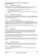
...P64-B supports two 3.3V expansion slots. The Intel Server Boards SE7320EP2 and SE7525RP2 implement one SATA controller and two SATA ports. Revision 1.0 23 Intel order number D24635-001 The USB controller moves data between the main memory and up to four USB connectors. The dual...40-pin connector. 3.2.3.4 USB Interface The 6300ESB ICH contains one EHCI USB 2.0 controller and four USB ports. Intel® Server Board SE7320EP2 / Intel® Server Board SE7525RP2 TPS Functional Architecture 3.2.3.1 PCI Bus P32-A I/O Subsystem The 6300ESB ICH provides a legacy 32-bit PCI subsystem and...
...P64-B supports two 3.3V expansion slots. The Intel Server Boards SE7320EP2 and SE7525RP2 implement one SATA controller and two SATA ports. Revision 1.0 23 Intel order number D24635-001 The USB controller moves data between the main memory and up to four USB connectors. The dual...40-pin connector. 3.2.3.4 USB Interface The 6300ESB ICH contains one EHCI USB 2.0 controller and four USB ports. Intel® Server Board SE7320EP2 / Intel® Server Board SE7525RP2 TPS Functional Architecture 3.2.3.1 PCI Bus P32-A I/O Subsystem The 6300ESB ICH provides a legacy 32-bit PCI subsystem and...
Product Specification
Page 27
... Serial A is designated by as "Serial A" on and power-off the system. 3.4 BIOS Flash The board incorporates an Intel® FWH flash memory component. The server boards provide a standard 34-pin interface for the floppy disk controller. 3.3.2.4 Keyboard and Mouse Two external ...device is a highperformance 8-megabit memory component and non-volatile storage space. The server boards have a "Serial_B" silkscreen label next to an external connector on the use of 6300ESB. Intel® Server Board SE7320EP2 / Intel® Server Board SE7525RP2 TPS Functional Architecture 3.3.2 Serial ...
... Serial A is designated by as "Serial A" on and power-off the system. 3.4 BIOS Flash The board incorporates an Intel® FWH flash memory component. The server boards provide a standard 34-pin interface for the floppy disk controller. 3.3.2.4 Keyboard and Mouse Two external ...device is a highperformance 8-megabit memory component and non-volatile storage space. The server boards have a "Serial_B" silkscreen label next to an external connector on the use of 6300ESB. Intel® Server Board SE7320EP2 / Intel® Server Board SE7525RP2 TPS Functional Architecture 3.3.2 Serial ...
Product Specification
Page 34
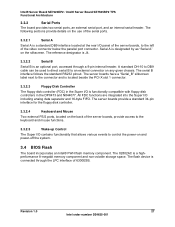
...standard ATX I /O Subsystem 5.2 Video Controller The server boards provide an ATI Rage XL PCI graphics accelerator, along with 8MB of video memory. As an option, the video controller can be set to 100Hz vertical refresh rate. Supported Supported Supported Supported Supported 32 bpp Supported ... under 2D, and up to support dual-monitor mode when an AGP adapter is detected in a 272pin PBGA. Intel® Server Board SE7320EP2 / Intel® Server Board SE7525RP2 TPS PCI I /O opening area. One 2Mx32-bit SDRAM chip provides 8MB of video SDRAM and support circuitry for...
...standard ATX I /O Subsystem 5.2 Video Controller The server boards provide an ATI Rage XL PCI graphics accelerator, along with 8MB of video memory. As an option, the video controller can be set to 100Hz vertical refresh rate. Supported Supported Supported Supported Supported 32 bpp Supported ... under 2D, and up to support dual-monitor mode when an AGP adapter is detected in a 272pin PBGA. Intel® Server Board SE7320EP2 / Intel® Server Board SE7525RP2 TPS PCI I /O opening area. One 2Mx32-bit SDRAM chip provides 8MB of video SDRAM and support circuitry for...

Product Specification
Page 35
...Intel® Server Board SE7525RP2 TPS PCI I/O Subsystem 5.2.2 Video Memory Interface The memory controller subsystem of the ATI Rage XL arbitrates requests from direct memory interface, the VGA graphics controller, the drawing coprocessor, the display controller, the video scalar, and hardware cursor. The following diagram shows the signals for video memory.... 5.2.3 Host Bus Interface The ATI Rage XL supports a PCI33 MHz bus. Video Controller PCI Bus Interface Revision 1.0 35 Intel order number D24635-001 The board supports ...
...Intel® Server Board SE7525RP2 TPS PCI I/O Subsystem 5.2.2 Video Memory Interface The memory controller subsystem of the ATI Rage XL arbitrates requests from direct memory interface, the VGA graphics controller, the drawing coprocessor, the display controller, the video scalar, and hardware cursor. The following diagram shows the signals for video memory.... 5.2.3 Host Bus Interface The ATI Rage XL supports a PCI33 MHz bus. Video Controller PCI Bus Interface Revision 1.0 35 Intel order number D24635-001 The board supports ...
Product Specification
Page 42
... is reported. 6.2.1.4 Mixed Processor Families Processor families cannot be identical to become the BSP. When awakened, an AP programs its Memory Type Range Registers (MTRRs) to be mixed in a system. If this condition is detected, an error is reported. 6.2.1.5 ... (PIC) and non-maskable interrupt (NMI)). If this condition is detected, an error is reported. Intel® Server Board SE7320EP2 / Intel® Server Board SE7525RP2 TPS BIOS 6.2 System Initialization 6.2.1 Processors 6.2.1.1 Multiple Processor Initialization IA-32 processors have mixed cache sizes,...
... is reported. 6.2.1.4 Mixed Processor Families Processor families cannot be identical to become the BSP. When awakened, an AP programs its Memory Type Range Registers (MTRRs) to be mixed in a system. If this condition is detected, an error is reported. 6.2.1.5 ... (PIC) and non-maskable interrupt (NMI)). If this condition is detected, an error is reported. Intel® Server Board SE7320EP2 / Intel® Server Board SE7525RP2 TPS BIOS 6.2 System Initialization 6.2.1 Processors 6.2.1.1 Multiple Processor Initialization IA-32 processors have mixed cache sizes,...


