Product Specification
Page 2
...from S5 4.0 Added the introduction of any features or instructions marked "reserved" or "undefined." Revision History Intel® Server Boards SE7320SP2 and SE7525GP2 Revision History Date June 2004 November 2004 September 2005 December 2005 Revision Number Modifications 1.0 Initial Release 2.0 Updated... Boards SE7320SP2 and SE7525GP2 may contain design defects or errors known as errata which may be provided in connection with this document. Intel may be claimed as provided in the section "3.5.4 - Updated supported processors matrix and BIOS setup options according to...
...from S5 4.0 Added the introduction of any features or instructions marked "reserved" or "undefined." Revision History Intel® Server Boards SE7320SP2 and SE7525GP2 Revision History Date June 2004 November 2004 September 2005 December 2005 Revision Number Modifications 1.0 Initial Release 2.0 Updated... Boards SE7320SP2 and SE7525GP2 may contain design defects or errors known as errata which may be provided in connection with this document. Intel may be claimed as provided in the section "3.5.4 - Updated supported processors matrix and BIOS setup options according to...
Product Specification
Page 5
Intel® Server Boards SE7320SP2 and SE7525GP2 Contents 4.3.3 Configuration Reset 60 4.3.4 Keyboard Commands 61 4.4 Entering BIOS Setup 62 4.4.1 Main Menu ...62 4.4.2 Advanced Menu...63 4.4.3 Boot Menu ...73 4.4.4 Security Menu...75 4.4.5 Server Menu ...76 4.4.6 Exit Menu...81 4.5 Flash Update Utility 81 4.6 Rolling BIOS and On-line Updates 81 4.7 Flash Update Utility 82 4.7.1 Flash BIOS ...82 4.7.2 User Binary...
Intel® Server Boards SE7320SP2 and SE7525GP2 Contents 4.3.3 Configuration Reset 60 4.3.4 Keyboard Commands 61 4.4 Entering BIOS Setup 62 4.4.1 Main Menu ...62 4.4.2 Advanced Menu...63 4.4.3 Boot Menu ...73 4.4.4 Security Menu...75 4.4.5 Server Menu ...76 4.4.6 Exit Menu...81 4.5 Flash Update Utility 81 4.6 Rolling BIOS and On-line Updates 81 4.7 Flash Update Utility 82 4.7.1 Flash BIOS ...82 4.7.2 User Binary...

Product Specification
Page 7
... Selection Jumper 160 8. General Specifications...161 8.1 Absolute Maximum Ratings 161 8.2 Mean Time Between Failure (MTBF 161 Revision 4.0 vii Intel® Server Boards SE7320SP2 and SE7525GP2 Contents 6.3 Checkpoints ...133 6.3.1 System ROM BIOS POST Task Test Point (Port 80h Code 133 6.3.2 Diagnostic LEDs 133 6.3.3 POST Code Checkpoints 135 6.3.4 Bootblock Initialization Code Checkpoints 137 6.3.5 Bootblock Recovery...
... Selection Jumper 160 8. General Specifications...161 8.1 Absolute Maximum Ratings 161 8.2 Mean Time Between Failure (MTBF 161 Revision 4.0 vii Intel® Server Boards SE7320SP2 and SE7525GP2 Contents 6.3 Checkpoints ...133 6.3.1 System ROM BIOS POST Task Test Point (Port 80h Code 133 6.3.2 Diagnostic LEDs 133 6.3.3 POST Code Checkpoints 135 6.3.4 Bootblock Initialization Code Checkpoints 137 6.3.5 Bootblock Recovery...
Product Specification
Page 9
... 10. Video Memory Interface 39 Table 15. BIOS Setup, Main Menu Options 62 Revision 4.0 ix IPMI-over-LAN ...106 Figure 17. Power Supply Control Signals 113 Figure 18. Output Voltage Timing 163 Figure 22. Intel® Server Board SE7525GP2 Layout Reference 7 Table 3. Processor Support Matrix...27 Table 9. Serial B Header Pin-out 42 Table 17. External Interfaces to mBMC 102 Figure 16. Sample BIOS Popup Menu 59 Table 21. Intel® Server Boards SE7320SP2 and SE7525GP2 Contents Figure 15. Video Modes ...38 Table 14. PCI Bus Segment Characteristics 30 Table 11.
... 10. Video Memory Interface 39 Table 15. BIOS Setup, Main Menu Options 62 Revision 4.0 ix IPMI-over-LAN ...106 Figure 17. Power Supply Control Signals 113 Figure 18. Output Voltage Timing 163 Figure 22. Intel® Server Board SE7525GP2 Layout Reference 7 Table 3. Processor Support Matrix...27 Table 9. Serial B Header Pin-out 42 Table 17. External Interfaces to mBMC 102 Figure 16. Sample BIOS Popup Menu 59 Table 21. Intel® Server Boards SE7320SP2 and SE7525GP2 Contents Figure 15. Video Modes ...38 Table 14. PCI Bus Segment Characteristics 30 Table 11.
Product Specification
Page 10
Contents Intel® Server Boards SE7320SP2 and SE7525GP2 Table 23. BIOS Setup, IDE Device Configuration Sub-menu Selections 67 Table 28. BIOS Setup, Removable Drives Sub-menu Selections 74 Table 39. BIOS Setup, Event Log Configuration Sub-menu Selections 80 Table 45. Security Features Operating Model 93 Table... Table 49. mBMC Factory Default Event Filters 110 Table 53. Fault/Status LED...118 Table 57. BIOS Setup, Floppy Configuration Sub-menu Selections 68 Table 29. BIOS Setup, Boot Device Priority Sub-menu Selections 74 Table 37. Chassis ID LEDs...118 Table 56. ...
Contents Intel® Server Boards SE7320SP2 and SE7525GP2 Table 23. BIOS Setup, IDE Device Configuration Sub-menu Selections 67 Table 28. BIOS Setup, Removable Drives Sub-menu Selections 74 Table 39. BIOS Setup, Event Log Configuration Sub-menu Selections 80 Table 45. Security Features Operating Model 93 Table... Table 49. mBMC Factory Default Event Filters 110 Table 53. Fault/Status LED...118 Table 57. BIOS Setup, Floppy Configuration Sub-menu Selections 68 Table 29. BIOS Setup, Boot Device Priority Sub-menu Selections 74 Table 37. Chassis ID LEDs...118 Table 56. ...

Product Specification
Page 11
... Table 84. NIC1 82541GI(10/100/1000) Connector Pin-out (JA1 152 Table 85. USB Connectors Pin-out (J3 154 Table 88. Intel® Server Boards SE7320SP2 and SE7525GP2 Contents Table 58. Boot Block Error Beep Codes 132 Table 62. DIM Code Checkpoints 139 Table 69. ACPI Runtime Checkpoints 139 Table 70... 146 Table 77. Remote Management Card Header Pin-out (J33 147 Table 79. ATA 40-pin Connector Pin-out (J41, J43 153 Table 86. Troubleshooting BIOS Beep Codes 132 Table 64. Memory Error Codes 140 Table 71. PCI Express* Slot Pin-out (J13 for x4, J14 for x16 149 Table 82...
... Table 84. NIC1 82541GI(10/100/1000) Connector Pin-out (JA1 152 Table 85. USB Connectors Pin-out (J3 154 Table 88. Intel® Server Boards SE7320SP2 and SE7525GP2 Contents Table 58. Boot Block Error Beep Codes 132 Table 62. DIM Code Checkpoints 139 Table 69. ACPI Runtime Checkpoints 139 Table 70... 146 Table 77. Remote Management Card Header Pin-out (J33 147 Table 79. ATA 40-pin Connector Pin-out (J41, J43 153 Table 86. Troubleshooting BIOS Beep Codes 132 Table 64. Memory Error Codes 140 Table 71. PCI Express* Slot Pin-out (J13 for x4, J14 for x16 149 Table 82...

Product Specification
Page 12
Intrusion Cable Connector (J19) Pin-out 158 Table 96. Transient Load Requirements 166 xii Revision 4.0 SCSI LED Header Pin-out (J26 158 Table 97. Intel® Xeon® Processor DP TDP Guidelines 162 Table 102. Turn On / Off Timing 164 Table 105. Three-pin Fan Headers Pin-out (J51, ... 103. Six-pin Fan headers Pin-out (J44, J46 158 Table 95. Absolute Maximum Ratings 161 Table 100. MTBF Calculation 161 Table 101. Contents Intel® Server Boards SE7320SP2 and SE7525GP2 Table 93. BIOS Bank Jumper Option 160 Table 99. Voltage Timing Parameters 163 Table 104.
Intrusion Cable Connector (J19) Pin-out 158 Table 96. Transient Load Requirements 166 xii Revision 4.0 SCSI LED Header Pin-out (J26 158 Table 97. Intel® Xeon® Processor DP TDP Guidelines 162 Table 102. Turn On / Off Timing 164 Table 105. Three-pin Fan Headers Pin-out (J51, ... 103. Six-pin Fan headers Pin-out (J44, J46 158 Table 95. Absolute Maximum Ratings 161 Table 100. MTBF Calculation 161 Table 101. Contents Intel® Server Boards SE7320SP2 and SE7525GP2 Table 93. BIOS Bank Jumper Option 160 Table 99. Voltage Timing Parameters 163 Table 104.

Product Specification
Page 13
... building blocks are used outside any of the Intel® Server Board SE7320SP2 and the Intel® Server Board SE7525GP2. It is divided into the following chapters ƒ Chapter 1: Introduction ƒ Chapter 2: Server Board Overview ƒ Chapter 3: Functional Architecture ƒ Chapter 4: System BIOS ƒ Chapter 5: Platform Management ƒ Chapter 6: Error Reporting and Handling ƒ...
... building blocks are used outside any of the Intel® Server Board SE7320SP2 and the Intel® Server Board SE7525GP2. It is divided into the following chapters ƒ Chapter 1: Introduction ƒ Chapter 2: Server Board Overview ƒ Chapter 3: Functional Architecture ƒ Chapter 4: System BIOS ƒ Chapter 5: Platform Management ƒ Chapter 6: Error Reporting and Handling ƒ...

Product Specification
Page 22
...run at a fixed speed and cannot be programmed to detect the presence and identity of 120 amps. 3.1.2 Reset Configuration Logic The BIOS determines the processor stepping, cache size, etc through the CPUID instruction. If the VIDs of the system. 10 Revision 4.0 At present... logic to operate at the same frequency; Prior to enabling the embedded VRD, circuitry on the VRD. Functional Architecture Intel® Server Boards SE7320SP2 and SE7525GP2 3.1.1 Processor Voltage Regulator Devices (VRDs) The server board has two voltage regulator devices (VRDs) that the following criteria...
...run at a fixed speed and cannot be programmed to detect the presence and identity of 120 amps. 3.1.2 Reset Configuration Logic The BIOS determines the processor stepping, cache size, etc through the CPUID instruction. If the VIDs of the system. 10 Revision 4.0 At present... logic to operate at the same frequency; Prior to enabling the embedded VRD, circuitry on the VRD. Functional Architecture Intel® Server Boards SE7320SP2 and SE7525GP2 3.1.1 Processor Voltage Regulator Devices (VRDs) The server board has two voltage regulator devices (VRDs) that the following criteria...
Product Specification
Page 24
...Intel Xeon Intel Xeon Intel Xeon Intel Xeon Intel Xeon Intel Xeon FSB Frequency 533 MHz 533 MHz 533 MHz 800 MHz 800 MHz 800 MHz 800 MHz 800 MHz 800 MHz Frequency 2.8 GHz 3.06 GHz 3.2 GHz 2.8 GHz 3.0 GHz 3.2 GHz 3.4 GHz 3.6 GHz 3.8 GHz Support No No No Yes Yes Yes Yes Yes Yes Note: The latest BIOS...support website for a complete list of these server boards. http://support.intel.com/support/motherboards/server/se7320sp2 http://support.intel.com/support/motherboards/server/se7525gp2 3.1.6.1 Processor Mis-population Detection The processors must be implemented before CPU socket 2.
...Intel Xeon Intel Xeon Intel Xeon Intel Xeon Intel Xeon Intel Xeon FSB Frequency 533 MHz 533 MHz 533 MHz 800 MHz 800 MHz 800 MHz 800 MHz 800 MHz 800 MHz Frequency 2.8 GHz 3.06 GHz 3.2 GHz 2.8 GHz 3.0 GHz 3.2 GHz 3.4 GHz 3.6 GHz 3.8 GHz Support No No No Yes Yes Yes Yes Yes Yes Note: The latest BIOS...support website for a complete list of these server boards. http://support.intel.com/support/motherboards/server/se7320sp2 http://support.intel.com/support/motherboards/server/se7525gp2 3.1.6.1 Processor Mis-population Detection The processors must be implemented before CPU socket 2.
Product Specification
Page 25
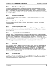
...microcode updates to modify the cache configuration, size or policies. The BIOS allows a number of free space available. There are not supported. 3.1.6.6 Jumperless Processor Speed Settings The Intel® Xeon® processor does not utilize jumpers or switches to ... value between all processors. The size of speeds supported by the BIOS. 3.1.6.3 Mixed Processor Models Processor models cannot be mixed in a system. Intel® Server Boards SE7320SP2 and SE7525GP2 Functional Architecture 3.1.6.2 Mixed Processor Steppings For optimum system performance, only identical...
...microcode updates to modify the cache configuration, size or policies. The BIOS allows a number of free space available. There are not supported. 3.1.6.6 Jumperless Processor Speed Settings The Intel® Xeon® processor does not utilize jumpers or switches to ... value between all processors. The size of speeds supported by the BIOS. 3.1.6.3 Mixed Processor Models Processor models cannot be mixed in a system. Intel® Server Boards SE7320SP2 and SE7525GP2 Functional Architecture 3.1.6.2 Mixed Processor Steppings For optimum system performance, only identical...
Product Specification
Page 26
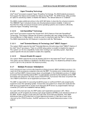
... provides. 3.1.7 Multiple Processor Initialization IA-32 processors have a microcode-based boot strap processor (BSP) arbitration protocol. The BIOS detects processors that support this feature. If the BSP determines that an AP exists that is programmed to the lowest-featured... the BSP. At boot time, the system is in the system. 14 Revision 4.0 Functional Architecture Intel® Server Boards SE7320SP2 and SE7525GP2 3.1.6.9 Hyper-Threading Technology Intel® Xeon® processors support Hyper-Threading Technology. It does not describe the virtual processors because some...
... provides. 3.1.7 Multiple Processor Initialization IA-32 processors have a microcode-based boot strap processor (BSP) arbitration protocol. The BIOS detects processors that support this feature. If the BSP determines that an AP exists that is programmed to the lowest-featured... the BSP. At boot time, the system is in the system. 14 Revision 4.0 Functional Architecture Intel® Server Boards SE7320SP2 and SE7525GP2 3.1.6.9 Hyper-Threading Technology Intel® Xeon® processors support Hyper-Threading Technology. It does not describe the virtual processors because some...

Product Specification
Page 35
... Tested Memory List on the support website for a list of supported memory: http://support.intel.com/support/motherboards/server/se7320sp2 http://support.intel.com/support/motherboards/server/se7525gp2 The BIOS reads the Serial Presence Detect (SPD) SEEPROMs on each installed memory module to determine the... Otherwise, go to be populated by Intel. 3.5.2 Memory Population The mixing of configured memory can be found using BIOS Setup. The bank can be further divided into two rows, based on Server Board SE7320SP2 and Server Board SE7525GP2. DIMM search rules for qualified DIMMs ...
... Tested Memory List on the support website for a list of supported memory: http://support.intel.com/support/motherboards/server/se7320sp2 http://support.intel.com/support/motherboards/server/se7525gp2 The BIOS reads the Serial Presence Detect (SPD) SEEPROMs on each installed memory module to determine the... Otherwise, go to be populated by Intel. 3.5.2 Memory Population The mixing of configured memory can be found using BIOS Setup. The bank can be further divided into two rows, based on Server Board SE7320SP2 and Server Board SE7525GP2. DIMM search rules for qualified DIMMs ...
Product Specification
Page 37
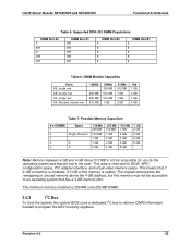
... 4 GB and 4 GB minus 512 MB is 256 MB (one 256 MB DIMM). 3.5.3 I2C Bus To boot the system, the system BIOS uses a dedicated I2C bus to retrieve DIMM information needed to the user. The chipset should allow the remapping of this memory may be accessible for... BIOS, APIC configuration space, PCI adapter interface, and virtual video memory space. The minimum memory installed is not be lost to program the MCH memory registers. Revision 4.0 25 Intel® Server Boards SE7320SP2 and SE7525GP2 Functional Architecture Table 5. Supported DDR-333...
... 4 GB and 4 GB minus 512 MB is 256 MB (one 256 MB DIMM). 3.5.3 I2C Bus To boot the system, the system BIOS uses a dedicated I2C bus to retrieve DIMM information needed to the user. The chipset should allow the remapping of this memory may be accessible for... BIOS, APIC configuration space, PCI adapter interface, and virtual video memory space. The minimum memory installed is not be lost to program the MCH memory registers. Revision 4.0 25 Intel® Server Boards SE7320SP2 and SE7525GP2 Functional Architecture Table 5. Supported DDR-333...
Product Specification
Page 38
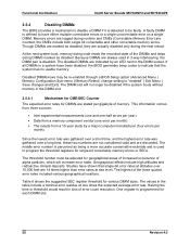
... registers for geographical areas of increased occurrence of alpha particles, which will no usable memory. This information comes from three sources: ƒ Intel experimental measurements (one and one-half errors per year) ƒ Data from a 10-year study by an LED next to the DIMM... shown that the system has no longer be faulty. If all DIMMs in loss of memory. Functional Architecture Intel® Server Boards SE7320SP2 and SE7525GP2 3.5.4 Disabling DIMMs The BIOS provides a mechanism to disable a DIMM if it is detected to be disabled if the system boots without memory...
... registers for geographical areas of increased occurrence of alpha particles, which will no usable memory. This information comes from three sources: ƒ Intel experimental measurements (one and one-half errors per year) ƒ Data from a 10-year study by an LED next to the DIMM... shown that the system has no longer be faulty. If all DIMMs in loss of memory. Functional Architecture Intel® Server Boards SE7320SP2 and SE7525GP2 3.5.4 Disabling DIMMs The BIOS provides a mechanism to disable a DIMM if it is detected to be disabled if the system boots without memory...

Product Specification
Page 39
...LED will be lit and the CME logging and detection will be disabled by BIOS. 3.5.5 Memory RASUM Features The Intel® E7320 MCH and Intel E7525 MCH support several memory RASUM (Reliability, Availability, Serviceability, Usability, and ...then the DIMM 2A LED will be lit and the CME logging and detection will be disabled by BIOS. If the CME count that occurs on Correctable Errors, Integrated Memory Initialization, and DIMM Sparing. ... counter value is also dependent on these server boards. Intel® Server Boards SE7320SP2 and SE7525GP2 Functional Architecture Table 8.
...LED will be lit and the CME logging and detection will be disabled by BIOS. 3.5.5 Memory RASUM Features The Intel® E7320 MCH and Intel E7525 MCH support several memory RASUM (Reliability, Availability, Serviceability, Usability, and ...then the DIMM 2A LED will be lit and the CME logging and detection will be disabled by BIOS. If the CME count that occurs on Correctable Errors, Integrated Memory Initialization, and DIMM Sparing. ... counter value is also dependent on these server boards. Intel® Server Boards SE7320SP2 and SE7525GP2 Functional Architecture Table 8.

Product Specification
Page 41
... a limited, very high speed memory test, and provides a BIOS-accessible memory zeroing capability for use by software, so it and...escalated as "leaky buckets," such that the spare DIMM be removed from service. Intel® Server Boards SE7320SP2 and SE7525GP2 Functional Architecture Note that any DIMM exceeds that will be at least the size...mirror happens to be enabled and disabled via configuration. 3.5.5.4 Integrated Memory Initialization Engine The Intel® E7320 and Intel E7525 MCHs provide hardware managed ECC auto-initialization of the largest primary DIMM in use...
... a limited, very high speed memory test, and provides a BIOS-accessible memory zeroing capability for use by software, so it and...escalated as "leaky buckets," such that the spare DIMM be removed from service. Intel® Server Boards SE7320SP2 and SE7525GP2 Functional Architecture Note that any DIMM exceeds that will be at least the size...mirror happens to be enabled and disabled via configuration. 3.5.5.4 Integrated Memory Initialization Engine The Intel® E7320 and Intel E7525 MCHs provide hardware managed ECC auto-initialization of the largest primary DIMM in use...

Product Specification
Page 43
... Express connector on the secondary side of x4 (2 GB/s). 3.6.1.4 P64-Express16: x16 PCI Express bus segment Intel® Server Board SE7525GP2 only: The P64-Express16 bus segment supports x16 PCI Express signaling. 3.6.1.5 Scan Order The BIOS assigns PCI bus numbers in a depth-first hierarchy, in the address range 0c0000h-0e7fffh and will be...
... Express connector on the secondary side of x4 (2 GB/s). 3.6.1.4 P64-Express16: x16 PCI Express bus segment Intel® Server Board SE7525GP2 only: The P64-Express16 bus segment supports x16 PCI Express signaling. 3.6.1.5 Scan Order The BIOS assigns PCI bus numbers in a depth-first hierarchy, in the address range 0c0000h-0e7fffh and will be...
Product Specification
Page 44
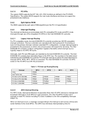
... level 2 of the integrated I/O APICs in the PCI BIOS Specification. Functional Architecture Intel® Server Boards SE7320SP2 and SE7525GP2 3.6.1.9 PCI APIs The system BIOS supports the INT 1Ah, AH = B1h functions as defined in the Intel 6300ESB I/O controller. 3.6.3.1 Legacy Interrupt Routing For PC-compatible mode, the Intel 6300ESB I/O controller provides two 82C59-compatible interrupt controllers. Interrupt...
... level 2 of the integrated I/O APICs in the PCI BIOS Specification. Functional Architecture Intel® Server Boards SE7320SP2 and SE7525GP2 3.6.1.9 PCI APIs The system BIOS supports the INT 1Ah, AH = B1h functions as defined in the Intel 6300ESB I/O controller. 3.6.3.1 Legacy Interrupt Routing For PC-compatible mode, the Intel 6300ESB I/O controller provides two 82C59-compatible interrupt controllers. Interrupt...

Product Specification
Page 48
... Pointer Register (offset 34h) will change to indicate that can be configured or enabled/disabled by accessing the BIOS Setup Utility during POST. The Intel® 6300ESB I /O controller DMA protocol redefines signals on the IDE cable to allow both the serial and...and conventions when accessing the register interface and follows standard command protocol conventions. Functional Architecture Intel® Server Boards SE7320SP2 and SE7525GP2 3.6.4 IDE Support Integrated IDE controllers of the Intel® 6300ESB I /O controller has separate PCI functions for both host and target ...
... Pointer Register (offset 34h) will change to indicate that can be configured or enabled/disabled by accessing the BIOS Setup Utility during POST. The Intel® 6300ESB I /O controller DMA protocol redefines signals on the IDE cable to allow both the serial and...and conventions when accessing the register interface and follows standard command protocol conventions. Functional Architecture Intel® Server Boards SE7320SP2 and SE7525GP2 3.6.4 IDE Support Integrated IDE controllers of the Intel® 6300ESB I /O controller has separate PCI functions for both host and target ...


