
Product Guide
Page 4
Installing Memory ...51 Cable Routing for Intel SC5200 Base Chassis 52 Cable Routing for Intel SC5200 Hot-Swap, Redundant Power Chassis 53 Making Connections to the Server Board 54 Installing the Serial B Cable 55 Finishing Up ...56 Replacing the Backup Battery ... Access 92 How to Set Up Remote Modem or Serial Access 94 How to Set Up Paging Alerts 96 How Set Up LAN Alerts 98 4 Intel Server Board SE7501HG2 Product Guide
Installing Memory ...51 Cable Routing for Intel SC5200 Base Chassis 52 Cable Routing for Intel SC5200 Hot-Swap, Redundant Power Chassis 53 Making Connections to the Server Board 54 Installing the Serial B Cable 55 Finishing Up ...56 Replacing the Backup Battery ... Access 92 How to Set Up Remote Modem or Serial Access 94 How to Set Up Paging Alerts 96 How Set Up LAN Alerts 98 4 Intel Server Board SE7501HG2 Product Guide

Product Guide
Page 14
...proper processor cooling, the fan inlet air temperature should be installed so that it faces the rear of the processor. 14 Intel Server Board SE7501HG2 Product Guide Restricting the airflow through the processor heat sink can cause overheating and subsequent failure of the chassis. When two .... See the installation instructions in this chassis, see the installation instructions beginning on page 46. When not using the Intel® Server Chassis SC5200 with hot swap redundant power, refer to the instructions in Chapter 2. Do not install the Processor Wind Tunnel when using the...
...proper processor cooling, the fan inlet air temperature should be installed so that it faces the rear of the processor. 14 Intel Server Board SE7501HG2 Product Guide Restricting the airflow through the processor heat sink can cause overheating and subsequent failure of the chassis. When two .... See the installation instructions in this chassis, see the installation instructions beginning on page 46. When not using the Intel® Server Chassis SC5200 with hot swap redundant power, refer to the instructions in Chapter 2. Do not install the Processor Wind Tunnel when using the...

Product Guide
Page 24
...; Server Management Intel Server Management (ISM) is a system management package that contains a ROM-DOS* operating system and DOS-based utilities, including the System Setup Utility, FRU/SDR Load Utility, and other times either the SSU or the SCW. ✏ NOTES SC5200 Server Chassis considerations: If you have configured the... active Serial Over LAN session from a remote location. • Real-time monitoring and alerting for use an optional service partition on Intel Server Management and the individual ISM applications, see the ISM CD. 24 Intel Server Board SE7501HG2 Product Guide
...; Server Management Intel Server Management (ISM) is a system management package that contains a ROM-DOS* operating system and DOS-based utilities, including the System Setup Utility, FRU/SDR Load Utility, and other times either the SSU or the SCW. ✏ NOTES SC5200 Server Chassis considerations: If you have configured the... active Serial Over LAN session from a remote location. • Real-time monitoring and alerting for use an optional service partition on Intel Server Management and the individual ISM applications, see the ISM CD. 24 Intel Server Board SE7501HG2 Product Guide

Product Guide
Page 32
... 12 V specification. For more information on supported processors and qualified memory and chassis components, see: http://support.intel.com/support/motherboards/server/SE7501HG2 Processor Minimum of supported processors, see : http://www.ssiforum.org Installation Notes Installation Process Quick Reference Step Remove ...to the server board Install the processor and processor wind tunnel in the Intel® Server Chassis SC5200 base chassis or in a reference chassis Install the processor in the Intel® Server Chassis SC5200 with 1.2 A +5 V standby current (in order to your system must...
... 12 V specification. For more information on supported processors and qualified memory and chassis components, see: http://support.intel.com/support/motherboards/server/SE7501HG2 Processor Minimum of supported processors, see : http://www.ssiforum.org Installation Notes Installation Process Quick Reference Step Remove ...to the server board Install the processor and processor wind tunnel in the Intel® Server Chassis SC5200 base chassis or in a reference chassis Install the processor in the Intel® Server Chassis SC5200 with 1.2 A +5 V standby current (in order to your system must...

Product Guide
Page 35
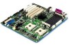
... server board. Failure to properly rearrange the metal standoffs may cause the server board to malfunction and may be different from the illustration. For the Intel SC5200 chassis: Standoffs are included with your chassis does not have standoffs placed as shown below, you must rearrange them so they match the holes in...
... server board. Failure to properly rearrange the metal standoffs may cause the server board to malfunction and may be different from the illustration. For the Intel SC5200 chassis: Standoffs are included with your chassis does not have standoffs placed as shown below, you must rearrange them so they match the holes in...

Product Guide
Page 37
Installing the Server Board 1. Place the board into the four standoffs that border the CPU2 socket. Placing the Server Board in a bag labeled "C." 1 2 Figure 8. Installations and Upgrades 37 Attach the board using the screws that the back panel I/O shield openings and chassis standoffs align correctly. 2. Attach fasteners at the nine locations marked below. For the Intel SC5200 chassis, these screws are packaged in the Chassis TP00106 ✏ NOTE If a single processor is to be used, insert screws into the chassis, making sure that are included with your chassis.
Installing the Server Board 1. Place the board into the four standoffs that border the CPU2 socket. Placing the Server Board in a bag labeled "C." 1 2 Figure 8. Installations and Upgrades 37 Attach the board using the screws that the back panel I/O shield openings and chassis standoffs align correctly. 2. Attach fasteners at the nine locations marked below. For the Intel SC5200 chassis, these screws are packaged in the Chassis TP00106 ✏ NOTE If a single processor is to be used, insert screws into the chassis, making sure that are included with your chassis.

Product Guide
Page 39
...Chassis Use these instructions if you are installing a processor and the Processor Wind Tunnel (PWT) in the SC5200 base chassis or in the Intel® Server Chassis SC5200 Hot Swap Redundant Power, disregard this chapter and the additional precautions given here. 2. Remove the chassis cover... (see your system by unplugging the AC power cord. 3. Lift the socket lever for instructions). 4. If you are installing the Server Board SE7501HG2 ...
...Chassis Use these instructions if you are installing a processor and the Processor Wind Tunnel (PWT) in the SC5200 base chassis or in the Intel® Server Chassis SC5200 Hot Swap Redundant Power, disregard this chapter and the additional precautions given here. 2. Remove the chassis cover... (see your system by unplugging the AC power cord. 3. Lift the socket lever for instructions). 4. If you are installing the Server Board SE7501HG2 ...

Product Guide
Page 46
... this chassis, do the following diagram) on page 39. For each SC5200 HSRP chassis. Insert and tighten two screws (letter B in the Intel® Chassis SC5200 HSRP. Installing the Processor Retention Brackets 46 Intel Server Board SE7501HG2 Product Guide Installing the Processor in the SC5200 Hot Swap Redundant Power Chassis ✏ NOTE Use these instructions if...
... this chassis, do the following diagram) on page 39. For each SC5200 HSRP chassis. Insert and tighten two screws (letter B in the Intel® Chassis SC5200 HSRP. Installing the Processor Retention Brackets 46 Intel Server Board SE7501HG2 Product Guide Installing the Processor in the SC5200 Hot Swap Redundant Power Chassis ✏ NOTE Use these instructions if...

Product Guide
Page 51
... the sides of the DIMM until the socket levers snap into the slots of supported memory, visit the Intel Support website: http://support.intel.com/support/motherboards/server/SE7501HG2 1. Pull the tabs at the bottom of the fan assembly to the retention mechanism. For chassis that... 3) will fit into place. 4. For chassis that require the PWT assembly (SC5200 Base chassis and reference chassis), reattach the fan assembly to snap them into the retention mechanism. ✏ NOTE When the SC5200 Hot Swap Redundant Chassis is allowed within a bank. Between banks only the DIMM...
... the sides of the DIMM until the socket levers snap into the slots of supported memory, visit the Intel Support website: http://support.intel.com/support/motherboards/server/SE7501HG2 1. Pull the tabs at the bottom of the fan assembly to the retention mechanism. For chassis that... 3) will fit into place. 4. For chassis that require the PWT assembly (SC5200 Base chassis and reference chassis), reattach the fan assembly to snap them into the retention mechanism. ✏ NOTE When the SC5200 Hot Swap Redundant Chassis is allowed within a bank. Between banks only the DIMM...

Product Guide
Page 52
IDE or SCSI Cables Cables that connect to devices in the lower device bays should be routed around the epac system fan carrier as shown. 2. Route cables as shown below . Routing Cables OM14556 52 Intel Server Board SE7501HG2 Product Guide Replace the top half of the epac. 1A 2A 1B 2B 3A 3B CPU1 Socket Figure 24. Installing Memory TP00104 Cable Routing for Intel SC5200 Base Chassis To ensure proper air-flow within the chassis, follow the cable routing guidelines below . 1. Figure 25.
IDE or SCSI Cables Cables that connect to devices in the lower device bays should be routed around the epac system fan carrier as shown. 2. Route cables as shown below . Routing Cables OM14556 52 Intel Server Board SE7501HG2 Product Guide Replace the top half of the epac. 1A 2A 1B 2B 3A 3B CPU1 Socket Figure 24. Installing Memory TP00104 Cable Routing for Intel SC5200 Base Chassis To ensure proper air-flow within the chassis, follow the cable routing guidelines below . 1. Figure 25.

Product Guide
Page 53
Front Panel Cable B. A A. Floppy Diskette Cable OM14376 Figure 26. Routing the Floppy and Front Panel Cables Cable Routing for Intel SC5200 Hot-Swap, Redundant Power Chassis Route the floppy drive cable and the hot-swap drive bay ICMB cable between the chassis wall and the hot-swap fan holder as shown. Routing the Floppy and ICMB Cables Installations and Upgrades 53 A B A. Floppy and Front Panel Cables Route the floppy drive and front panel cables as shown below at location A. Cable Routing Location OM14377 Figure 27.
Front Panel Cable B. A A. Floppy Diskette Cable OM14376 Figure 26. Routing the Floppy and Front Panel Cables Cable Routing for Intel SC5200 Hot-Swap, Redundant Power Chassis Route the floppy drive cable and the hot-swap drive bay ICMB cable between the chassis wall and the hot-swap fan holder as shown. Routing the Floppy and ICMB Cables Installations and Upgrades 53 A B A. Floppy and Front Panel Cables Route the floppy drive and front panel cables as shown below at location A. Cable Routing Location OM14377 Figure 27.

Product Guide
Page 55
Connecting it as shown. 2. Screw Figure 29. Intel® SC5200 Base Server Chassis Note Connect front system fans to the System Fan 3 and System Fan ... B OM14557 A. Installing the Serial B Cable Installations and Upgrades 55 Installing the Serial B Cable For the Intel SC5200 chassis, you can be found on the system fan carrier and on the system fan cables. Chassis Back Panel Cutout... B. Intel SC5200 Hot-Swap, Redundant Power Server Chassis Note Be sure to attach system fans to the back panel is ...
Connecting it as shown. 2. Screw Figure 29. Intel® SC5200 Base Server Chassis Note Connect front system fans to the System Fan 3 and System Fan ... B OM14557 A. Installing the Serial B Cable Installations and Upgrades 55 Installing the Serial B Cable For the Intel SC5200 chassis, you can be found on the system fan carrier and on the system fan cables. Chassis Back Panel Cutout... B. Intel SC5200 Hot-Swap, Redundant Power Server Chassis Note Be sure to attach system fans to the back panel is ...

Product Guide
Page 101
The other is through the Server Configuration Utilities menu. Select the appropriate chassis type (SC5200 or Other) and Continue. 7. These entries are prompted to load the FRU/SDR records. Use the Resource CD to boot the server..., you are optional. Review the system date and time for each method follow. Select Server Configuration Utilities and Continue. 3. Select the appropriate chassis type (SC5200 or Other). 5. To use the Server Configuration Wizard > Server Configuration Utilities menu to load the FRU/SDR records: 1. Instructions for accuracy and Continue. ...
The other is through the Server Configuration Utilities menu. Select the appropriate chassis type (SC5200 or Other) and Continue. 7. These entries are prompted to load the FRU/SDR records. Use the Resource CD to boot the server..., you are optional. Review the system date and time for each method follow. Select Server Configuration Utilities and Continue. 3. Select the appropriate chassis type (SC5200 or Other). 5. To use the Server Configuration Wizard > Server Configuration Utilities menu to load the FRU/SDR records: 1. Instructions for accuracy and Continue. ...