
Product Guide
Page 3
Contents 1 Description...8 Server Board Features ...8 Server Board Connector and Component Locations 10 Back Panel Connectors 11 Intel® E7501 Chipset 12 Processor ...13 Memory ...15 PCI I/O Subsystem ...15 Video ...17 SCSI Controller...18 IDE Controller ...18 USB Interface ...18 Network ... 22 Field Replaceable Units and Sensor Data Records 22 System Event Log ...22 Platform Event Management 23 Emergency Management Port 23 Intel® Server Management 24 Security ...25 Summary of Software Security Features 25 Secure Mode ...27 Password Protection 28 Intrusion Switch Monitoring...
Contents 1 Description...8 Server Board Features ...8 Server Board Connector and Component Locations 10 Back Panel Connectors 11 Intel® E7501 Chipset 12 Processor ...13 Memory ...15 PCI I/O Subsystem ...15 Video ...17 SCSI Controller...18 IDE Controller ...18 USB Interface ...18 Network ... 22 Field Replaceable Units and Sensor Data Records 22 System Event Log ...22 Platform Event Management 23 Emergency Management Port 23 Intel® Server Management 24 Security ...25 Summary of Software Security Features 25 Secure Mode ...27 Password Protection 28 Intrusion Switch Monitoring...

Product Guide
Page 6
... Chassis Standoffs 35 Figure 7. Routing the Floppy and Front Panel Cables 53 Figure 12. Processor and Wind Tunnel Installed 45 Figure 23. Applying Thermal Grease 48 6 Intel Server Board SE7501HG2 Product Guide Placing the Server Board in the Chassis 37 Figure 9. Installing the Serial ... / New Zealand 132 9 Equipment Log Worksheet 133 Equipment Log ...133 Index ...135 Figures Figure 1. Opening Socket Lever and Attaching Processor 39 Figure 16. Installing the I/O Shield 34 Figure 6. Attaching Retention Mechanism 40 Figure 17. Routing the Floppy and ICMB Cables 53...
... Chassis Standoffs 35 Figure 7. Routing the Floppy and Front Panel Cables 53 Figure 12. Processor and Wind Tunnel Installed 45 Figure 23. Applying Thermal Grease 48 6 Intel Server Board SE7501HG2 Product Guide Placing the Server Board in the Chassis 37 Figure 9. Installing the Serial ... / New Zealand 132 9 Equipment Log Worksheet 133 Equipment Log ...133 Index ...135 Figures Figure 1. Opening Socket Lever and Attaching Processor 39 Figure 16. Installing the I/O Shield 34 Figure 6. Attaching Retention Mechanism 40 Figure 17. Routing the Floppy and ICMB Cables 53...
Product Guide
Page 7
... Software Security Features 25 Keyboard Commands 64 On-Screen Options 64 Menu Selection Bar 65 Main Menu Selections 65 Primary/Secondary, Master/Slave Submenu 66 Processor Settings Submenu 66 Advanced Menu 67 PCI Configuration Submenu 67 PCI Configuration, Embedded Devices Submenu 68 Peripheral Configuration Submenu 68 Memory Configuration Submenu 69 Advanced...
... Software Security Features 25 Keyboard Commands 64 On-Screen Options 64 Menu Selection Bar 65 Main Menu Selections 65 Primary/Secondary, Master/Slave Submenu 66 Processor Settings Submenu 66 Advanced Menu 67 PCI Configuration Submenu 67 PCI Configuration, Embedded Devices Submenu 68 Peripheral Configuration Submenu 68 Memory Configuration Submenu 69 Advanced...

Product Guide
Page 8
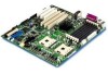
... RJ-45 connections Adaptec* AIC-7902 dual-channel U320 SCSI controller Continued 1 DDR200 compliant ECC DIMMs can be used only if 400 MHz processors are installed. 8 Intel Server Board SE7501HG2 Product Guide 1 Description Server Board Features The Intel® server board SE7501HG2 offers a "flat" design, with the processors and memory subsystems residing on the board. Table 1.
... RJ-45 connections Adaptec* AIC-7902 dual-channel U320 SCSI controller Continued 1 DDR200 compliant ECC DIMMs can be used only if 400 MHz processors are installed. 8 Intel Server Board SE7501HG2 Product Guide 1 Description Server Board Features The Intel® server board SE7501HG2 offers a "flat" design, with the processors and memory subsystems residing on the board. Table 1.

Product Guide
Page 12
... ECC DIMMs can be used only if 400 MHz processors are installed 12 Intel Server Board SE7501HG2 Product Guide The SE7501HG2 uses the following : • Full support of ECC on the memory bus • Full support of Intel® x4 Single Device Data Correction on the memory... P64H2 (I/O Bridge) • An HI 1.5 bus that provides an interface to all PC-compatible I /O subsystem core (PCI). Intel® E7501 Chipset The SE7501HG2 server includes the Intel E7501 chipset (MCH, ICH3-S, P64H2), which provides an integrated I/O bridge and memory controller, and a flexible I /O devices and ...
... ECC DIMMs can be used only if 400 MHz processors are installed 12 Intel Server Board SE7501HG2 Product Guide The SE7501HG2 uses the following : • Full support of ECC on the memory bus • Full support of Intel® x4 Single Device Data Correction on the memory... P64H2 (I/O Bridge) • An HI 1.5 bus that provides an interface to all PC-compatible I /O subsystem core (PCI). Intel® E7501 Chipset The SE7501HG2 server includes the Intel E7501 chipset (MCH, ICH3-S, P64H2), which provides an integrated I/O bridge and memory controller, and a flexible I /O devices and ...

Product Guide
Page 13
... port. or level-sensitive interrupts. Parallel Port The SE7501HG2 baseboard provides a 25-pin parallel port back panel connector. Serial port B port can be empty. Processor The Intel® Server Board SE7501HG2 accommodates one processor is available on the back panel for add-in ...A DH10 10-pin serial header is installed, it should be in cards. BIOS programming of supported processors, see: http://support.intel.com/support/motherboards/server/SE7501HG2 Description 13 When disabled, the interrupt is compatible with either or both disconnected. Instead, they are ...
... port. or level-sensitive interrupts. Parallel Port The SE7501HG2 baseboard provides a 25-pin parallel port back panel connector. Serial port B port can be empty. Processor The Intel® Server Board SE7501HG2 accommodates one processor is available on the back panel for add-in ...A DH10 10-pin serial header is installed, it should be in cards. BIOS programming of supported processors, see: http://support.intel.com/support/motherboards/server/SE7501HG2 Description 13 When disabled, the interrupt is compatible with either or both disconnected. Instead, they are ...

Product Guide
Page 14
... fan inlet air temperature should be installed so that it faces the rear of the processor. 14 Intel Server Board SE7501HG2 Product Guide See the installation instructions in the SE7501HG2 Quick Start User's Guide. Restricting the airflow through the processor heat sink can cause overheating and subsequent failure of the chassis. For this document, the...
... fan inlet air temperature should be installed so that it faces the rear of the processor. 14 Intel Server Board SE7501HG2 Product Guide See the installation instructions in the SE7501HG2 Quick Start User's Guide. Restricting the airflow through the processor heat sink can cause overheating and subsequent failure of the chassis. For this document, the...

Product Guide
Page 20
... hardware changes were made to the system while it was off. • S5: Soft off only when the AC power is disconnected. 20 Intel Server Board SE7501HG2 Product Guide sleep entry and wake-up sources for an overview. Pressing the power button or another wakeup event restores the system state from... wakeup event. • S4: Hibernate or Save to Disk. In this state the power supply is still on and the processors dissipate some power, so the power supply fan and processor fans continue to disk. CAUTION The system is off . The system can put the system into a sleep state in ACPI mode...
... hardware changes were made to the system while it was off. • S5: Soft off only when the AC power is disconnected. 20 Intel Server Board SE7501HG2 Product Guide sleep entry and wake-up sources for an overview. Pressing the power button or another wakeup event restores the system state from... wakeup event. • S4: Hibernate or Save to Disk. In this state the power supply is still on and the processors dissipate some power, so the power supply fan and processor fans continue to disk. CAUTION The system is off . The system can put the system into a sleep state in ACPI mode...

Product Guide
Page 22
...of fans, processors, or power supplies in the server. The BIOS, software, and other sensor-related events. The SEL is configured. FRUs can also log events by using the System Setup Utility. 22 Intel Server Board SE7501HG2 Product Guide You...functions: • Monitors system components and sensors, including processors, memory, fans, power supplies, temperature sensors, and chassis intrusion sensors. • Manages nonvolatile storage for system management activities. Baseboard Management Controller Intel server boards incorporate a baseboard management controller (BMC), which...
...of fans, processors, or power supplies in the server. The BIOS, software, and other sensor-related events. The SEL is configured. FRUs can also log events by using the System Setup Utility. 22 Intel Server Board SE7501HG2 Product Guide You...functions: • Monitors system components and sensors, including processors, memory, fans, power supplies, temperature sensors, and chassis intrusion sensors. • Manages nonvolatile storage for system management activities. Baseboard Management Controller Intel server boards incorporate a baseboard management controller (BMC), which...

Product Guide
Page 23
... of range • Voltage sensor out of range • Fan failure • Chassis intrusion • Power supply failure • Memory error • POST error • Processor fault resilient booting (FRB) failure • Fatal nonmaskable interrupt (NMI) from a source other actions by the BMC. the BMC dials a paging service and sends a predefined... interfaces with either of the Serial B port, with remote access software, such as the Direct Platform Control or the Client System Setup Utility applications in Intel Server Management.
... of range • Voltage sensor out of range • Fan failure • Chassis intrusion • Power supply failure • Memory error • POST error • Processor fault resilient booting (FRB) failure • Fatal nonmaskable interrupt (NMI) from a source other actions by the BMC. the BMC dials a paging service and sends a predefined... interfaces with either of the Serial B port, with remote access software, such as the Direct Platform Control or the Client System Setup Utility applications in Intel Server Management.

Product Guide
Page 32
...chassis manual Page 39 Page 46 Page 51 1 DDR200 compliant registered ECC DIMMs can be used only if 400 MHz processors are installed. 32 Intel Server Board SE7501HG2 Product Guide You must meet the following minimum requirements. Refer also to support Wake On LAN* (WOL)) and ... support [ATX], which meets the SSI EPS 12 V specification. For more information on supported processors and qualified memory and chassis components, see : http://support.intel.com/support/motherboards/server/SE7501HG2 Memory Minimum of two 128 MB ECC, DDR266-compliant registered SDRAM 184-pin gold DIMMs.1 Power...
...chassis manual Page 39 Page 46 Page 51 1 DDR200 compliant registered ECC DIMMs can be used only if 400 MHz processors are installed. 32 Intel Server Board SE7501HG2 Product Guide You must meet the following minimum requirements. Refer also to support Wake On LAN* (WOL)) and ... support [ATX], which meets the SSI EPS 12 V specification. For more information on supported processors and qualified memory and chassis components, see : http://support.intel.com/support/motherboards/server/SE7501HG2 Memory Minimum of two 128 MB ECC, DDR266-compliant registered SDRAM 184-pin gold DIMMs.1 Power...

Product Guide
Page 35
...Failure to properly rearrange the metal standoffs may cause the server board to malfunction and may be different from the illustration. For the Intel SC5200 chassis: Standoffs are included with your chassis does not have standoffs placed as shown below, you must rearrange them so they ... damage it. Install standoffs in positions 5, 13, 19, and in the eight positions marked P, regardless of whether one or two processors will be installed. Installing Chassis Standoffs If your chassis. Installing Chassis Standoffs TP00105 ✏ NOTE Install standoffs in the eight positions marked P.
...Failure to properly rearrange the metal standoffs may cause the server board to malfunction and may be different from the illustration. For the Intel SC5200 chassis: Standoffs are included with your chassis does not have standoffs placed as shown below, you must rearrange them so they ... damage it. Install standoffs in positions 5, 13, 19, and in the eight positions marked P, regardless of whether one or two processors will be installed. Installing Chassis Standoffs If your chassis. Installing Chassis Standoffs TP00105 ✏ NOTE Install standoffs in the eight positions marked P.

Product Guide
Page 37
For the Intel SC5200 chassis, these screws are included with your chassis. Attach the board using the screws that are packaged in the Chassis TP00106 ✏ NOTE If a single processor is to be used, insert screws into the chassis, making sure that border the CPU2 socket. Placing the Server Board in a bag labeled "C." 1 2 Figure 8. Installing the Server Board 1. Attach fasteners at the nine locations marked below. Place the board into the four standoffs that the back panel I/O shield openings and chassis standoffs align correctly. 2. Installations and Upgrades 37
For the Intel SC5200 chassis, these screws are included with your chassis. Attach the board using the screws that are packaged in the Chassis TP00106 ✏ NOTE If a single processor is to be used, insert screws into the chassis, making sure that border the CPU2 socket. Placing the Server Board in a bag labeled "C." 1 2 Figure 8. Installing the Server Board 1. Attach fasteners at the nine locations marked below. Place the board into the four standoffs that the back panel I/O shield openings and chassis standoffs align correctly. 2. Installations and Upgrades 37

Product Guide
Page 38
Make sure your customer service representative or visit the Intel Customer Support website: http://support.intel.com/support/motherboards/server/SE7501HG2 ESD and handling processors: Reduce the risk of electrostatic discharge (ESD) damage to the processor by doing the following: (1) Touch the metal chassis before touching the processor or server board. This socket is inappropriate for your...
Make sure your customer service representative or visit the Intel Customer Support website: http://support.intel.com/support/motherboards/server/SE7501HG2 ESD and handling processors: Reduce the risk of electrostatic discharge (ESD) damage to the processor by doing the following: (1) Touch the metal chassis before touching the processor or server board. This socket is inappropriate for your...

Product Guide
Page 39
... in a Reference Chassis Use these instructions if you are installing the Server Board SE7501HG2 in the Intel® Server Chassis SC5200 Hot Swap Redundant Power, disregard this chapter and the additional precautions given here. 2. If you are installing a processor and the Processor Wind Tunnel (PWT) in the SC5200 base chassis or in the SC5200...
... in a Reference Chassis Use these instructions if you are installing the Server Board SE7501HG2 in the Intel® Server Chassis SC5200 Hot Swap Redundant Power, disregard this chapter and the additional precautions given here. 2. If you are installing a processor and the Processor Wind Tunnel (PWT) in the SC5200 base chassis or in the SC5200...

Product Guide
Page 40
Applying Thermal Grease 40 Intel Server Board SE7501HG2 Product Guide 6. Install the PWT retention mechanism over the top of the processor with the screws provided, as shown in Figure 10. Apply thermal grease to the processor as shown in Figure 11. OM15037 Figure 10. OM15040 Figure 11. Attaching Retention Mechanism 7.
Applying Thermal Grease 40 Intel Server Board SE7501HG2 Product Guide 6. Install the PWT retention mechanism over the top of the processor with the screws provided, as shown in Figure 10. Apply thermal grease to the processor as shown in Figure 11. OM15037 Figure 10. OM15040 Figure 11. Attaching Retention Mechanism 7.

Product Guide
Page 41
... figure below, the flat end must point toward the rear of the retention clips to lock them into place. Position the retention clips over the processor and set it to -side motion. Engage each retention clip while sliding it into place over the plastic tabs at the center of the retention...
... figure below, the flat end must point toward the rear of the retention clips to lock them into place. Position the retention clips over the processor and set it to -side motion. Engage each retention clip while sliding it into place over the plastic tabs at the center of the retention...

Product Guide
Page 44
... 1 cable to the server board at location J7F1 and/or attach CPU Fan 2 cable at the sides of the retention mechanism apart slightly. If two processors are installed, the fans will fit into the slots of the fan assembly to back. Make sure the PWT is aligned so the fan is... the airflow is toward the I/O shield. 14. Attach the fan assembly to the Retention Mechanism ✏ NOTE System airflow must be side by side. 44 Intel Server Board SE7501HG2 Product Guide
... 1 cable to the server board at location J7F1 and/or attach CPU Fan 2 cable at the sides of the retention mechanism apart slightly. If two processors are installed, the fans will fit into the slots of the fan assembly to back. Make sure the PWT is aligned so the fan is... the airflow is toward the I/O shield. 14. Attach the fan assembly to the Retention Mechanism ✏ NOTE System airflow must be side by side. 44 Intel Server Board SE7501HG2 Product Guide

Product Guide
Page 45
Processor and Wind Tunnel Installed TP00016 Installations and Upgrades 45 A B USB Figure 16. The dashed lines over CPU2 (Figure 16, B) indicate that this processor assembly is indicated by the arrow at (Figure 16, A). When assembled, the Processor Wind Tunnel will look similar to the figure below. The direction of the airflow is only required when configuring the server with two processors.
Processor and Wind Tunnel Installed TP00016 Installations and Upgrades 45 A B USB Figure 16. The dashed lines over CPU2 (Figure 16, B) indicate that this processor assembly is indicated by the arrow at (Figure 16, A). When assembled, the Processor Wind Tunnel will look similar to the figure below. The direction of the airflow is only required when configuring the server with two processors.

Product Guide
Page 46
... the bracket to the board. Two sets of brackets included with each bracket, do not install the Processor Wind Tunnel. Installing the Processor Retention Brackets 46 Intel Server Board SE7501HG2 Product Guide B A OM14144 Figure 17. When installing the processor in the SC5200 Base chassis or in a reference chassis, disregard this chassis, do the following diagram...
... the bracket to the board. Two sets of brackets included with each bracket, do not install the Processor Wind Tunnel. Installing the Processor Retention Brackets 46 Intel Server Board SE7501HG2 Product Guide B A OM14144 Figure 17. When installing the processor in the SC5200 Base chassis or in a reference chassis, disregard this chassis, do the following diagram...


