
Product Guide
Page 3
... 22 Field Replaceable Units and Sensor Data Records 22 System Event Log ...22 Platform Event Management 23 Emergency Management Port 23 Intel® Server Management 24 Security ...25 Summary of Software Security Features 25 Secure Mode ...27 Password Protection 28 Intrusion Switch ...Regulatory Compliance 31 Minimum Hardware Requirements 32 Installation Notes...32 Installation Procedures...33 Installing the I/O Gasket and Shield 33 Installing Chassis Standoffs 35 Installing the Rubber Bumper 36 Installing the Server Board 37 Installing or Replacing Processor(s 38 Contents 3
... 22 Field Replaceable Units and Sensor Data Records 22 System Event Log ...22 Platform Event Management 23 Emergency Management Port 23 Intel® Server Management 24 Security ...25 Summary of Software Security Features 25 Secure Mode ...27 Password Protection 28 Intrusion Switch ...Regulatory Compliance 31 Minimum Hardware Requirements 32 Installation Notes...32 Installation Procedures...33 Installing the I/O Gasket and Shield 33 Installing Chassis Standoffs 35 Installing the Rubber Bumper 36 Installing the Server Board 37 Installing or Replacing Processor(s 38 Contents 3

Product Guide
Page 6
... Fan 42 Figure 20. Attaching the Heat Sink Fan to the Server Board 54 Figure 10. Attaching the Label to the I /O Shield 34 Figure 6. Configuring Chassis Standoffs 35 Figure 7. Routing Cables...52 Figure 11. Installing Processors 47 Figure 26. Making Connections to the...18. Raising the Locking Bar 47 Figure 25. Attaching the Top Assembly to the I/O Shield 33 Figure 4. Back Panel Connectors 11 Figure 3. Applying Thermal Grease 48 6 Intel Server Board SE7501HG2 Product Guide Attaching Retention Mechanism 40 Figure 17. Attaching the Gasket to the Retention Mechanism...
... Fan 42 Figure 20. Attaching the Heat Sink Fan to the Server Board 54 Figure 10. Attaching the Label to the I /O Shield 34 Figure 6. Configuring Chassis Standoffs 35 Figure 7. Routing Cables...52 Figure 11. Installing Processors 47 Figure 26. Making Connections to the...18. Raising the Locking Bar 47 Figure 25. Attaching the Top Assembly to the I/O Shield 33 Figure 4. Back Panel Connectors 11 Figure 3. Applying Thermal Grease 48 6 Intel Server Board SE7501HG2 Product Guide Attaching Retention Mechanism 40 Figure 17. Attaching the Gasket to the Retention Mechanism...

Product Guide
Page 19
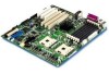
... on LAN (WOL) • Advanced Networking Service Features Description 19 Supported Network Features The SE7501HG2 supports the following features of the 82546EB controller: • 32-bit PCI bus master interface... bus utilization • Early receive interrupt for concurrent processing of each other, with a shielded LAN cable. The NIC is a 10BASE-T/100BASE-TX/1000BASE-TX network solution based on the... 132 MB/s. As a PCI bus master, the controller can be used with NIC2 on the Intel 82546EB single-chip Fast Ethernet PCI Bus Controller. The NICs are stacked on top of receive data...
... on LAN (WOL) • Advanced Networking Service Features Description 19 Supported Network Features The SE7501HG2 supports the following features of the 82546EB controller: • 32-bit PCI bus master interface... bus utilization • Early receive interrupt for concurrent processing of each other, with a shielded LAN cable. The NIC is a 10BASE-T/100BASE-TX/1000BASE-TX network solution based on the... 132 MB/s. As a PCI bus master, the controller can be used with NIC2 on the Intel 82546EB single-chip Fast Ethernet PCI Bus Controller. The NICs are stacked on top of receive data...

Product Guide
Page 32
... on supported processors and qualified memory and chassis components, see: http://support.intel.com/support/motherboards/server/SE7501HG2 Processor Minimum of supported processors, see : http://www.ssiforum.org Installation Notes... Installation Process Quick Reference Step Remove the access cover Install the I/O shield Install the standoffs Install the rubber bumper Install the server board Connect cables to the server board Install the processor and processor wind tunnel in the Intel...
... on supported processors and qualified memory and chassis components, see: http://support.intel.com/support/motherboards/server/SE7501HG2 Processor Minimum of supported processors, see : http://www.ssiforum.org Installation Notes... Installation Process Quick Reference Step Remove the access cover Install the I/O shield Install the standoffs Install the rubber bumper Install the server board Connect cables to the server board Install the processor and processor wind tunnel in the Intel...

Product Guide
Page 33
... the two backing strips from inside face of a chassis. Press the gasket onto the inside the chassis. If the shield does not fit the chassis, obtain a properly sized shield from the chassis supplier. Attaching the Gasket to the I /O Shield 1. Attaching the Gasket to minimize EMI. TP00028 Figure 3. Installation Procedures Installing the I/O Gasket and...
... the two backing strips from inside face of a chassis. Press the gasket onto the inside the chassis. If the shield does not fit the chassis, obtain a properly sized shield from the chassis supplier. Attaching the Gasket to the I /O Shield 1. Attaching the Gasket to minimize EMI. TP00028 Figure 3. Installation Procedures Installing the I/O Gasket and...

Product Guide
Page 34
... into the rectangular opening until it into place all the way around. Position one edge so that match the I /O Shield OM14625 34 Intel Server Board SE7501HG2 Product Guide Installing the I /O ports on the inner chassis wall. 2. Remove the backing from inside the chassis before installing the server board. 1. Press the label ...
... into the rectangular opening until it into place all the way around. Position one edge so that match the I /O Shield OM14625 34 Intel Server Board SE7501HG2 Product Guide Installing the I /O ports on the inner chassis wall. 2. Remove the backing from inside the chassis before installing the server board. 1. Press the label ...

Product Guide
Page 37
Installing the Server Board 1. For the Intel SC5200 chassis, these screws are included with your chassis. Place the board into the four standoffs that border the CPU2 socket. Attach the board using the screws that the back panel I/O shield openings and chassis standoffs align correctly. 2. Placing the Server Board in the Chassis TP00106 ✏ NOTE If a single processor is to be used, insert screws into the chassis, making sure that are packaged in a bag labeled "C." 1 2 Figure 8. Attach fasteners at the nine locations marked below. Installations and Upgrades 37
Installing the Server Board 1. For the Intel SC5200 chassis, these screws are included with your chassis. Place the board into the four standoffs that border the CPU2 socket. Attach the board using the screws that the back panel I/O shield openings and chassis standoffs align correctly. 2. Placing the Server Board in the Chassis TP00106 ✏ NOTE If a single processor is to be used, insert screws into the chassis, making sure that are packaged in a bag labeled "C." 1 2 Figure 8. Attach fasteners at the nine locations marked below. Installations and Upgrades 37

Product Guide
Page 44
... 2a 1 1 4 3b 2b OM15045 Figure 15. Attaching the Top Assembly to the Retention Mechanism ✏ NOTE System airflow must be side by side. 44 Intel Server Board SE7501HG2 Product Guide If two processors are installed, the fans will fit into the retention mechanism. Lower the fan assembly into the slots of the... to the server board at location J7F1 and/or attach CPU Fan 2 cable at the sides of the chassis and the airflow is toward the I/O shield.
... 2a 1 1 4 3b 2b OM15045 Figure 15. Attaching the Top Assembly to the Retention Mechanism ✏ NOTE System airflow must be side by side. 44 Intel Server Board SE7501HG2 Product Guide If two processors are installed, the fans will fit into the retention mechanism. Lower the fan assembly into the slots of the... to the server board at location J7F1 and/or attach CPU Fan 2 cable at the sides of the chassis and the airflow is toward the I/O shield.

Product Guide
Page 131
...Operation with cables, connected to peripherals, that interference will not occur in a residential installation. This equipment generates, uses, and can be shielded and grounded. Any changes or modifications not expressly approved by one to which can radiate radio frequency energy and, if not installed and ...used to connect to Part 15 of this product, contact: Intel Corporation 5200 N.E. Elam Young Parkway Hillsboro, OR 97124 1-800-628-8686 This equipment has been tested and found to comply with the...
...Operation with cables, connected to peripherals, that interference will not occur in a residential installation. This equipment generates, uses, and can be shielded and grounded. Any changes or modifications not expressly approved by one to which can radiate radio frequency energy and, if not installed and ...used to connect to Part 15 of this product, contact: Intel Corporation 5200 N.E. Elam Young Parkway Hillsboro, OR 97124 1-800-628-8686 This equipment has been tested and found to comply with the...
Product Guide
Page 136
... retention clips, 51 HI 2.0 bus interface, 13 Hot Key, 89 hot key option quick reference, 79 Hot keys, 28 I/O PCI expansion slots, 9 ports provided, 10 I/O shield, 33, 45 Intel Server Board SE7501HG2 Product Guide
... retention clips, 51 HI 2.0 bus interface, 13 Hot Key, 89 hot key option quick reference, 79 Hot keys, 28 I/O PCI expansion slots, 9 ports provided, 10 I/O shield, 33, 45 Intel Server Board SE7501HG2 Product Guide