
Product Guide
Page 4
...Intel SC5200 Base Chassis 52 Cable Routing for Intel SC5200 Hot-Swap, Redundant Power Chassis 53 Making Connections to the Server Board 54 Installing the Serial B Cable 55 Finishing Up ...56 Replacing the Backup Battery 57 3 POST and the BIOS... Device Priority 62 Using BIOS Setup ...62 Record Your Setup Settings 62 If BIOS Setup Is Inaccessible 62 ...Upgrading the BIOS ...77 Preparing for the Upgrade 77 Performing the BIOS Upgrade 78 Recovering the BIOS 78 Changing the BIOS Language 78...Sensor Data Records 90 Updating System Firmware and BIOS 91 Managing the Server Remotely 92 How to...
...Intel SC5200 Base Chassis 52 Cable Routing for Intel SC5200 Hot-Swap, Redundant Power Chassis 53 Making Connections to the Server Board 54 Installing the Serial B Cable 55 Finishing Up ...56 Replacing the Backup Battery 57 3 POST and the BIOS... Device Priority 62 Using BIOS Setup ...62 Record Your Setup Settings 62 If BIOS Setup Is Inaccessible 62 ...Upgrading the BIOS ...77 Preparing for the Upgrade 77 Performing the BIOS Upgrade 78 Recovering the BIOS 78 Changing the BIOS Language 78...Sensor Data Records 90 Updating System Firmware and BIOS 91 Managing the Server Remotely 92 How to...

Product Guide
Page 5
... Diskettes...104 Installing a Service Partition (Optional 105 Saving and Restoring Using the Intel Server tMheanSaygsetemmenCt oannfdigIunrtaetli®onS.M...a..R...T...T..o..o..l..(.O...p.t..io..n..a..l 110068 Installing Intel Server Management 109 Installing Intel SMaRT Tool 109 5 Solving Problems 111 Resetting the System ...111 Initial System ...117 PCI Installation Tips 118 Problems with Application Software 118 Bootable CD-ROM Is Not Detected 118 Recovering the BIOS...119 Clearing the Password with the Password Jumper 121 Clearing the CMOS ...122 Clearing CMOS with the Front...
... Diskettes...104 Installing a Service Partition (Optional 105 Saving and Restoring Using the Intel Server tMheanSaygsetemmenCt oannfdigIunrtaetli®onS.M...a..R...T...T..o..o..l..(.O...p.t..io..n..a..l 110068 Installing Intel Server Management 109 Installing Intel SMaRT Tool 109 5 Solving Problems 111 Resetting the System ...111 Initial System ...117 PCI Installation Tips 118 Problems with Application Software 118 Bootable CD-ROM Is Not Detected 118 Recovering the BIOS...119 Clearing the Password with the Password Jumper 121 Clearing the CMOS ...122 Clearing CMOS with the Front...
Product Guide
Page 7
... 127 Configuration Jumper (J1J1 127 Contents 7 Table 7. Table 16. Table 20. Table 23. Table 32. Table 34. Replacing the Back up Battery 58 Figure 32. BIOS Recovery Jumper 119 Figure 33. Table 6. Table 11. Table 15. Table 30. Table 31. Table 10. Table 19. Installing the Heat Sink 49 Figure 29...
... 127 Configuration Jumper (J1J1 127 Contents 7 Table 7. Table 16. Table 20. Table 23. Table 32. Table 34. Replacing the Back up Battery 58 Figure 32. BIOS Recovery Jumper 119 Figure 33. Table 6. Table 11. Table 15. Table 30. Table 31. Table 10. Table 19. Installing the Heat Sink 49 Figure 29...

Product Guide
Page 9
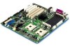
... and 1.9, ECP, compatible 25-pin connector • Two serial ports: One a-synch 9-pin RS-232C, one via 10-pin internal connector One Ethernet controller (Intel 82546EB) providing two 1-gigabit RJ45 connections Five USB ports: three stacked USB connectors in I/O rear panel, two via 10-pin internal header • SSI-EEB... 3.0 compliant • Power/Sleep Switch with LED Indicator • Wake on LAN* (WOL) • Wake on Ring (WOR) • BIOS password • Keyboard password protection • Floppy write-protect • SSI-EEB 3.0 compliant form factor Description 9
... and 1.9, ECP, compatible 25-pin connector • Two serial ports: One a-synch 9-pin RS-232C, one via 10-pin internal connector One Ethernet controller (Intel 82546EB) providing two 1-gigabit RJ45 connections Five USB ports: three stacked USB connectors in I/O rear panel, two via 10-pin internal header • SSI-EEB... 3.0 compliant • Power/Sleep Switch with LED Indicator • Wake on LAN* (WOL) • Wake on Ring (WOR) • BIOS password • Keyboard password protection • Floppy write-protect • SSI-EEB 3.0 compliant form factor Description 9

Product Guide
Page 13
...does not include an option to the floppy disk drive from the floppy disk controller. The system can be empty. Processor The Intel® Server Board SE7501HG2 accommodates one of the server board, are PS/2 compatible and are available for add-in the socket labeled CPU1 and the other ...back panel for the Serial A port. Serial port B port can be set to select the type of supported processors, see: http://support.intel.com/support/motherboards/server/SE7501HG2 Description 13 BIOS programming of which can be booted with the system bus at 400 MHz or at system startup.
...does not include an option to the floppy disk drive from the floppy disk controller. The system can be empty. Processor The Intel® Server Board SE7501HG2 accommodates one of the server board, are PS/2 compatible and are available for add-in the socket labeled CPU1 and the other ...back panel for the Serial A port. Serial port B port can be set to select the type of supported processors, see: http://support.intel.com/support/motherboards/server/SE7501HG2 Description 13 BIOS programming of which can be booted with the system bus at 400 MHz or at system startup.

Product Guide
Page 17
... Supported Supported Supported Supported - Zero Channel RAID The SE7501HG2 server board supports two Zero Channel RAID cards: the Intel® SRCZCR RAID Adapter and the Adaptec* ASR-2010S... RAID adapter. Supported - - - Segment A: 32-bit/33 MHz PCI Subsystem The 32-bit / 33 MHz PCI segment includes the following : • BIOS compatibility with Z Buffer Enabled Supported Supported Supported Supported Supported Supported Supported Supported Supported Supported Supported Supported Supported Supported - - SE7501HG2...
... Supported Supported Supported Supported - Zero Channel RAID The SE7501HG2 server board supports two Zero Channel RAID cards: the Intel® SRCZCR RAID Adapter and the Adaptec* ASR-2010S... RAID adapter. Supported - - - Segment A: 32-bit/33 MHz PCI Subsystem The 32-bit / 33 MHz PCI segment includes the following : • BIOS compatibility with Z Buffer Enabled Supported Supported Supported Supported Supported Supported Supported Supported Supported Supported Supported Supported Supported Supported - - SE7501HG2...

Product Guide
Page 19
...Disabling the controller disables both NIC ports. ✏ NOTE To ensure EMC product regulation compliance, the system must be disabled through the BIOS setup menu. A flash device stores the network ID • Support for access to 132 MB/s. Network Interface Controller The server board ... Interface Controllers (NIC) that prevent data overruns or underruns while waiting for Wake on the Intel 82546EB single-chip Fast Ethernet PCI Bus Controller. Supported Network Features The SE7501HG2 supports the following features of the 82546EB controller: • 32-bit PCI bus master interface...
...Disabling the controller disables both NIC ports. ✏ NOTE To ensure EMC product regulation compliance, the system must be disabled through the BIOS setup menu. A flash device stores the network ID • Support for access to 132 MB/s. Network Interface Controller The server board ... Interface Controllers (NIC) that prevent data overruns or underruns while waiting for Wake on the Intel 82546EB single-chip Fast Ethernet PCI Bus Controller. Supported Network Features The SE7501HG2 supports the following features of the 82546EB controller: • 32-bit PCI bus master interface...

Product Guide
Page 21
This provides an option for operations such as the Emergency Management Port. Wakeup Events The SE7501HG2 system supports several wakeup events. If the system is in the S1 or S4 state, it powered down the system. Description 21 If the system ... Ring Indicate RI signals from a S4 or S5 sleep state, even if the operating system disabled Wake on RTC alarm allows system power to provide BIOS boot option. If the system is used as after-hours maintenance. Wake on LAN Wake on Ring allows system power to be activated through the...
This provides an option for operations such as the Emergency Management Port. Wakeup Events The SE7501HG2 system supports several wakeup events. If the system is in the S1 or S4 state, it powered down the system. Description 21 If the system ... Ring Indicate RI signals from a S4 or S5 sleep state, even if the operating system disabled Wake on RTC alarm allows system power to provide BIOS boot option. If the system is used as after-hours maintenance. Wake on LAN Wake on Ring allows system power to be activated through the...

Product Guide
Page 22
... type, and type-specific information, such as chassis part number, must be read using the System Setup Utility. 22 Intel Server Board SE7501HG2 Product Guide Intel® server boards are major modules in a nonvolatile storage component on page 81. The SEL is stored in the ...system for converting a sensor reading into the hardware and provides additional features through Intel® Server Management software. The BIOS, software,...
... type, and type-specific information, such as chassis part number, must be read using the System Setup Utility. 22 Intel Server Board SE7501HG2 Product Guide Intel® server boards are major modules in a nonvolatile storage component on page 81. The SEL is stored in the ...system for converting a sensor reading into the hardware and provides additional features through Intel® Server Management software. The BIOS, software,...

Product Guide
Page 25
...Floppy Options, and specify Floppy Access as read only. All enabled secure mode features go to wait for a password. continued Description 25 Security The SE7501HG2 BIOS provides a number of Software Security Features The table below refers to other System Setup Utility menus and to a diskette unless a password is entered... not have to the Security Subsystem Group menu. At boot time, if a CD is entered, the server boots from or write to the BIOS Setup utility. When the password is detected in the CD-ROM drive or a diskette in drive A, the system prompts for the inactivity time-out...
...Floppy Options, and specify Floppy Access as read only. All enabled secure mode features go to wait for a password. continued Description 25 Security The SE7501HG2 BIOS provides a number of Software Security Features The table below refers to other System Setup Utility menus and to a diskette unless a password is entered... not have to the Security Subsystem Group menu. At boot time, if a CD is entered, the server boots from or write to the BIOS Setup utility. When the password is detected in the CD-ROM drive or a diskette in drive A, the system prompts for the inactivity time-out...

Product Guide
Page 26
... enabled, the server will fully boot but only the supervisor password will require a password before the system completes the boot sequence, the BIOS automatically detects and tests the keyboard if it to the system other than SSU: set user password Boot without a keyboard. The sequence... If both the supervisor and user passwords are enabled through Setup. During POST, before accepting any keyboard or mouse input. 26 Intel Server Board SE7501HG2 Product Guide To resume activity: Enter the correct password(s). To clear the password if you cannot access Setup, change the Clear Password...
... enabled, the server will fully boot but only the supervisor password will require a password before the system completes the boot sequence, the BIOS automatically detects and tests the keyboard if it to the system other than SSU: set user password Boot without a keyboard. The sequence... If both the supervisor and user passwords are enabled through Setup. During POST, before accepting any keyboard or mouse input. 26 Intel Server Board SE7501HG2 Product Guide To resume activity: Enter the correct password(s). To clear the password if you cannot access Setup, change the Clear Password...

Product Guide
Page 27
... power or reset the server from the front panel switches. However, until the user password is entered, mouse and keyboard input is configured through the BIOS setup options or through Setup. Using Secure Boot When secure mode is in effect, the system will be configured as valid hot keys. ✏ NOTE...
... power or reset the server from the front panel switches. However, until the user password is entered, mouse and keyboard input is configured through the BIOS setup options or through Setup. Using Secure Boot When secure mode is in effect, the system will be configured as valid hot keys. ✏ NOTE...

Product Guide
Page 28
...• Must enter the administrator password to enter BIOS Setup. • Must enter the administrator password to boot the server if Password on Boot is difficult to break the password by changing it to a null string. 28 Intel Server Board SE7501HG2 Product Guide Numbers from the NumLock pad are not... case-sensitive. Setting Passwords Each password can be booted into a halt state. When set , you : • May enter the user password to enter BIOS Setup. See the Secure Boot Mode...
...• Must enter the administrator password to enter BIOS Setup. • Must enter the administrator password to boot the server if Password on Boot is difficult to break the password by changing it to a null string. 28 Intel Server Board SE7501HG2 Product Guide Numbers from the NumLock pad are not... case-sensitive. Setting Passwords Each password can be booted into a halt state. When set , you : • May enter the user password to enter BIOS Setup. See the Secure Boot Mode...

Product Guide
Page 58
...at the beginning of the battery according to observe the correct polarity, insert it in the plastic retainer. Open the chassis. 3. Run BIOS Setup to restore the configuration settings to lift the battery. 4. Gently push down on the screwdriver to the RTC. Remove the battery...of a small flat-blade screwdriver, or equivalent, under the tab in the battery socket. 7. Replacing the Back up Battery TP00036 58 Intel Server Board SE7501HG2 Product Guide 1. Dispose of this chapter. 2. Remove the new lithium battery from its package, and, being careful to local ordinance. 6.
...at the beginning of the battery according to observe the correct polarity, insert it in the plastic retainer. Open the chassis. 3. Run BIOS Setup to restore the configuration settings to lift the battery. 4. Gently push down on the screwdriver to the RTC. Remove the battery...of a small flat-blade screwdriver, or equivalent, under the tab in the battery socket. 7. Replacing the Back up Battery TP00036 58 Intel Server Board SE7501HG2 Product Guide 1. Dispose of this chapter. 2. Remove the new lithium battery from its package, and, being careful to local ordinance. 6.

Product Guide
Page 61
...following message is able to pop up a boot menu when POST finishes. What appears on the screen after this depends on the system, the BIOS begins executing the Power-On Self-Test (POST), which one. this boot only (see "Using the Adaptec SCSI Utility" on your service ...a fatal system error that requires immediate attention. Press if there are SCSI devices installed. If POST can choose the boot device or enter BIOS Setup. POST discovers, configures, and tests the processors, memory, keyboard, and most installed peripheral devices. When the utility opens, follow the...
...following message is able to pop up a boot menu when POST finishes. What appears on the screen after this depends on the system, the BIOS begins executing the Power-On Self-Test (POST), which one. this boot only (see "Using the Adaptec SCSI Utility" on your service ...a fatal system error that requires immediate attention. Press if there are SCSI devices installed. If POST can choose the boot device or enter BIOS Setup. POST discovers, configures, and tests the processors, memory, keyboard, and most installed peripheral devices. When the utility opens, follow the...

Product Guide
Page 62
...Your Setup Settings Record your BIOS setup settings. At any time during POST, press . if the values and the actual hardware do not agree, POST generates an error message. To clear CMOS, either of the selections on the baseboard. 62 Intel Server Board SE7501HG2 Product Guide When POST ...completes, a popup Boot menu displays. 3. POST uses these values to access BIOS Setup, you select "ATAPI CD-ROM Drive." ✏ NOTE One of two methods ...
...Your Setup Settings Record your BIOS setup settings. At any time during POST, press . if the values and the actual hardware do not agree, POST generates an error message. To clear CMOS, either of the selections on the baseboard. 62 Intel Server Board SE7501HG2 Product Guide When POST ...completes, a popup Boot menu displays. 3. POST uses these values to access BIOS Setup, you select "ATAPI CD-ROM Drive." ✏ NOTE One of two methods ...

Product Guide
Page 63
...The bottom portion of the Setup screen provides a list of features. POST and the BIOS Setup Utility 63 This message is enabled (Default), you will temporarily disable the splash screen allowing you ...will see this condition, the BIOS will load default values for navigating the Setup utility. To see the message, press ... CMOS time and date not set In this prompt: Press to enter SETUP ✏ NOTE If the BIOS setup option "POST Diagnostic Screen" is hidden by pressing while at the DOS operating system prompt •...
...The bottom portion of the Setup screen provides a list of features. POST and the BIOS Setup Utility 63 This message is enabled (Default), you will temporarily disable the splash screen allowing you ...will see this condition, the BIOS will load default values for navigating the Setup utility. To see the message, press ... CMOS time and date not set In this prompt: Press to enter SETUP ✏ NOTE If the BIOS setup option "POST Diagnostic Screen" is hidden by pressing while at the DOS operating system prompt •...

Product Guide
Page 65
...). Selects the diskette type. Displays IDE device selection. Displays IDE device selection. Selects the language displayed by the BIOS. POST and the BIOS Setup Utility 65 Enters submenu. Displays the IDE device selection. Main Menu Selections Feature System Time Choices HH:MM:...US) Spanish Italian French German Description Sets the system time (hour, minutes, seconds, on Vendor, Processor, Memory, Peripherals, and BIOS Selects boot options and power supply controls Exit Saves or discards changes to become ready. Enters submenu. Enters submenu. When English (...
...). Selects the diskette type. Displays IDE device selection. Displays IDE device selection. Selects the language displayed by the BIOS. POST and the BIOS Setup Utility 65 Enters submenu. Displays the IDE device selection. Main Menu Selections Feature System Time Choices HH:MM:...US) Spanish Italian French German Description Sets the system time (hour, minutes, seconds, on Vendor, Processor, Memory, Peripherals, and BIOS Selects boot options and power supply controls Exit Saves or discards changes to become ready. Enters submenu. Enters submenu. When English (...

Product Guide
Page 66
...Only Information Only Information Only Information Only Description Displays the measured processor speed. Reports the CPU ID for processor 2. 66 Intel Server Board SE7501HG2 Product Guide Table 9. LBA Mode Control Disabled Enabled This field is detected. Multi-Sector Transfer Disabled 2 Sectors 4 Sectors...PIO Mode Standard 1 2 3 3 / DMA 1 4 4 / DMA 2 This field is informational only. Table 10. When enabled, the BIOS will clear the processor status history and retest all processors at the next boot. When disabled, hyper-threading is disabled if no devices are transferred...
...Only Information Only Information Only Information Only Description Displays the measured processor speed. Reports the CPU ID for processor 2. 66 Intel Server Board SE7501HG2 Product Guide Table 9. LBA Mode Control Disabled Enabled This field is detected. Multi-Sector Transfer Disabled 2 Sectors 4 Sectors...PIO Mode Standard 1 2 3 3 / DMA 1 4 4 / DMA 2 This field is informational only. Table 10. When enabled, the BIOS will clear the processor status history and retest all processors at the next boot. When disabled, hyper-threading is disabled if no devices are transferred...

Product Guide
Page 67
Enters submenu. When disabled, the logo screen is not displayed if the BIOS does not detect a valid logo in the flash file. The system automatically resets this option disables serial redirection. Table 12. Enables or disables the option ... sleep button will not be available if there are no advanced chipset settings that can make the following selections on . Enters submenu. POST and the BIOS Setup Utility 67 Enters submenu. Disabling this field to clear the server configuration data during the next boot. Enables or disables the option ROM scan...
Enters submenu. When disabled, the logo screen is not displayed if the BIOS does not detect a valid logo in the flash file. The system automatically resets this option disables serial redirection. Table 12. Enables or disables the option ... sleep button will not be available if there are no advanced chipset settings that can make the following selections on . Enters submenu. POST and the BIOS Setup Utility 67 Enters submenu. Disabling this field to clear the server configuration data during the next boot. Enables or disables the option ROM scan...


