Product Guide
Page 3
... ...13 Hot Swappable SCSI Hard Drives 13 Flex Bay...14 500 Watt Redundant Power Supply 14 480 Watt Power Supply ...14 System Cooling ...14 Chassis Security...15 Locking and Unlocking the Front Bezel 15 2 Assembling the System Before You Begin ...17 Supplies Needed ...17 Installation/Assembly Safety Instructions 18...Components 21 Remove the Cover...21 Remove the Processor Air Duct 22 Remove the Riser Cards 23 Remove the Fan module 24 Install the Server Board 25 Routing Cables ...28 Installing Peripherals ...34 Installing a PCI Card on a Riser Card 35 Installing the Riser Cards on the...
... ...13 Hot Swappable SCSI Hard Drives 13 Flex Bay...14 500 Watt Redundant Power Supply 14 480 Watt Power Supply ...14 System Cooling ...14 Chassis Security...15 Locking and Unlocking the Front Bezel 15 2 Assembling the System Before You Begin ...17 Supplies Needed ...17 Installation/Assembly Safety Instructions 18...Components 21 Remove the Cover...21 Remove the Processor Air Duct 22 Remove the Riser Cards 23 Remove the Fan module 24 Install the Server Board 25 Routing Cables ...28 Installing Peripherals ...34 Installing a PCI Card on a Riser Card 35 Installing the Riser Cards on the...
Product Guide
Page 4
... Power Supply Module 53 Replacing a Power Supply Cage 54 Installing a Redundant Fan 56 Replacing the Fan Module 58 Replacing a Backplane Board 59 Replacing a Front Panel Board 60 Replacing a Server Board 61 A Regulatory and Certification Information Product Regulatory Compliance 63 Product Safety Compliance 63 Product EMC Compliance 63 Product Regulatory Compliance Markings 64...C Safety Warnings WARNING: English (US 74 AVERTISSEMENT: Français 76 WARNUNG: Deutsch ...78 AVVERTENZA: Italiano ...80 ADVERTENCIAS: Español 82 iv Intel SR2300 Chassis Subassembly Product Guide
... Power Supply Module 53 Replacing a Power Supply Cage 54 Installing a Redundant Fan 56 Replacing the Fan Module 58 Replacing a Backplane Board 59 Replacing a Front Panel Board 60 Replacing a Server Board 61 A Regulatory and Certification Information Product Regulatory Compliance 63 Product Safety Compliance 63 Product EMC Compliance 63 Product Regulatory Compliance Markings 64...C Safety Warnings WARNING: English (US 74 AVERTISSEMENT: Français 76 WARNUNG: Deutsch ...78 AVVERTENZA: Italiano ...80 ADVERTENCIAS: Español 82 iv Intel SR2300 Chassis Subassembly Product Guide
Product Guide
Page 5
...drive/FDD Module 40 28. Replacing a DVD/CD-ROM drive/FDD Module 49 33. Chassis Front ...9 3. Peripherals ...13 6. Removing the Cover 21 7. Installing the Riser Cards 37 25. Chassis Back...10 4. Removing a Riser Card 23 9. Connecting Fans to the Carrier 39 27...37. System Components 8 2. Mounting the Server Board SE7500WV2 26 11. Cable Routing...28 13. Attaching the Drive to the Server Board 30 16. Removing the Low-Profile PCI Riser Card 51 34. D Warranty Limited Warranty for Intel® Chassis Subassembly Products 85 Extent of Limited Warranty 85...
...drive/FDD Module 40 28. Replacing a DVD/CD-ROM drive/FDD Module 49 33. Chassis Front ...9 3. Peripherals ...13 6. Removing the Cover 21 7. Installing the Riser Cards 37 25. Chassis Back...10 4. Removing a Riser Card 23 9. Connecting Fans to the Carrier 39 27...37. System Components 8 2. Mounting the Server Board SE7500WV2 26 11. Cable Routing...28 13. Attaching the Drive to the Server Board 30 16. Removing the Low-Profile PCI Riser Card 51 34. D Warranty Limited Warranty for Intel® Chassis Subassembly Products 85 Extent of Limited Warranty 85...

Product Guide
Page 6
Removing the Fan Blank 56 39. Removing the Front Panel Board 60 43. Power Usage Worksheet 1 71 4. LED Indicator Status 12 3. Removing the Fan module 58 41. Removing the Server Board 61 Tables 1. Power Usage Worksheet 2 72 vi Intel SR2300 Chassis Subassembly Product Guide Installing the New Fan 57 40. Control Button Functions 12 2. 38. Replacing a Backplane Board 59 42.
Removing the Fan Blank 56 39. Removing the Front Panel Board 60 43. Power Usage Worksheet 1 71 4. LED Indicator Status 12 3. Removing the Fan module 58 41. Removing the Server Board 61 Tables 1. Power Usage Worksheet 2 72 vi Intel SR2300 Chassis Subassembly Product Guide Installing the New Fan 57 40. Control Button Functions 12 2. 38. Replacing a Backplane Board 59 42.
Product Guide
Page 7
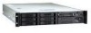
1 Chassis Description Your Intel® SR2300 server chassis kit is designed to backplane board) • One Resource CD-ROM containing drivers, utilities, and product guide • Mounting screws (server board) • Front, mid, or 4-post rack mounting kit Items You Must Purchase Separately The following components: • 2U rack-mount chassis featuring: Four hard drive bays with carriers and...
1 Chassis Description Your Intel® SR2300 server chassis kit is designed to backplane board) • One Resource CD-ROM containing drivers, utilities, and product guide • Mounting screws (server board) • Front, mid, or 4-post rack mounting kit Items You Must Purchase Separately The following components: • 2U rack-mount chassis featuring: Four hard drive bays with carriers and...
Product Guide
Page 8
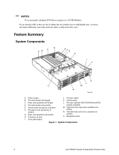
Riser card assembly (full-length) D. Front panel board Figure 1. Feature Summary System Components D C AB EFG H I . PCI add-in card (accessory to system) O. Tape drive bay (tape drive available from others... duct L. Hard drive bay (one of six, accessory to system) G. Control panel C. PCI card bracket (low-profile) E. Server board (accessory to the card. System Components 8 Intel SR2300 Chassis Subassembly Product Guide Riser card assembly (low-profile) H. Backplane board I J K L O M N OM14080 A. If you install a NIC in the top slot of a CD-ROM drive....
Riser card assembly (full-length) D. Front panel board Figure 1. Feature Summary System Components D C AB EFG H I . PCI add-in card (accessory to system) O. Tape drive bay (tape drive available from others... duct L. Hard drive bay (one of six, accessory to system) G. Control panel C. PCI card bracket (low-profile) E. Server board (accessory to the card. System Components 8 Intel SR2300 Chassis Subassembly Product Guide Riser card assembly (low-profile) H. Backplane board I J K L O M N OM14080 A. If you install a NIC in the top slot of a CD-ROM drive....

Product Guide
Page 15
... turn ). Turn the lock clockwise until it stops (about a quarter turn ). Chassis Security To help prevent unauthorized access to the Baseboard Management Controller (BMC) on the server board, where server management software processes the signal. The bezel is now unlocked and can be opened ...again. The bezel is now locked and cannot be monitored by server management software. The chassis also includes a preinstalled intrusion ...
... turn ). Turn the lock clockwise until it stops (about a quarter turn ). Chassis Security To help prevent unauthorized access to the Baseboard Management Controller (BMC) on the server board, where server management software processes the signal. The bezel is now unlocked and can be opened ...again. The bezel is now locked and cannot be monitored by server management software. The chassis also includes a preinstalled intrusion ...

Product Guide
Page 17
... fully integrated system should have the following supplies available: • Anti-static wrist strap (recommended) • SR2300 accessory kit (included) • SE7500WV2 SCSI server board kit • Processors and memory you purchased separately to add to the server board • Optional peripherals and add-in cards you want to include in the system 17 2 Assembling the...
... fully integrated system should have the following supplies available: • Anti-static wrist strap (recommended) • SR2300 accessory kit (included) • SE7500WV2 SCSI server board kit • Processors and memory you purchased separately to add to the server board • Optional peripherals and add-in cards you want to include in the system 17 2 Assembling the...
Product Guide
Page 25
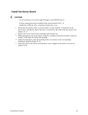
... the SR2300 chassis. Assembling the System 25 If installed in the chassis accessory kit (Figure 10, D). Remove the server board from its packaging and antistatic bag. 3. Attach the board to the chassis using the three screws shipped in a different order, component damage may occur. 1. Install the Server Board CAUTION Do not install any server board support bumpers in the rear chassis wall...
... the SR2300 chassis. Assembling the System 25 If installed in the chassis accessory kit (Figure 10, D). Remove the server board from its packaging and antistatic bag. 3. Attach the board to the chassis using the three screws shipped in a different order, component damage may occur. 1. Install the Server Board CAUTION Do not install any server board support bumpers in the rear chassis wall...

Product Guide
Page 26
C A D OM14090 Figure 10. Mounting the Server Board SE7500WV2 26 Intel SR2300 Chassis Subassembly Product Guide
C A D OM14090 Figure 10. Mounting the Server Board SE7500WV2 26 Intel SR2300 Chassis Subassembly Product Guide

Product Guide
Page 27
Install processors and memory, following the directions on the Intel Server Board SE7500WV2 Quick Start User Guide. 7. D A B C Figure 11. Installing the Processor Air Dam OM14579 Assembling the System 27 If you only install one processor, you must install the processor air dam. b. 6. Put the air dam(D) into place. a. Attach processor retention piece (B) to the server board (C) using the provided screws (A).
Install processors and memory, following the directions on the Intel Server Board SE7500WV2 Quick Start User Guide. 7. D A B C Figure 11. Installing the Processor Air Dam OM14579 Assembling the System 27 If you only install one processor, you must install the processor air dam. b. 6. Put the air dam(D) into place. a. Attach processor retention piece (B) to the server board (C) using the provided screws (A).
Product Guide
Page 28
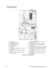
... Power 7 F 2 K 2 2 or 3 4 5 1. Fan module to backplane E. To server board auxiliary signal connector from power supply OM14091 C. Tape Drive (optional) 5. Server Board A. Cable Routing 28 Intel SR2300 Chassis Subassembly Product Guide SCSI cable from server board to server board fan connectors (2) H. USB ribbon cable from server board to server board F. To backplane power connector from power supply J. To server board auxiliary power connector from power supply B. Front Panel...
... Power 7 F 2 K 2 2 or 3 4 5 1. Fan module to backplane E. To server board auxiliary signal connector from power supply OM14091 C. Tape Drive (optional) 5. Server Board A. Cable Routing 28 Intel SR2300 Chassis Subassembly Product Guide SCSI cable from server board to server board fan connectors (2) H. USB ribbon cable from server board to server board F. To backplane power connector from power supply J. To server board auxiliary power connector from power supply B. Front Panel...

Product Guide
Page 29
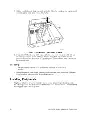
... down on the fan module, slide it is connected to the white 24-pin connector on the chassis and lower the fan module onto the floor. 4. B B A OM14616 Figure 13. Connect the main server board power cable to the white 6-pin connector. 2. Connecting the Main Power Cable Install the Fan module... and the corresponding holes in the fan module with the raised tabs on the server board. Verify that the P6 backplane power cable is routed from the power supply to the backplane board and is just above the chassis floor. 3. Align the holes in the bottom of arrow (2) until the latch...
... down on the fan module, slide it is connected to the white 24-pin connector on the chassis and lower the fan module onto the floor. 4. B B A OM14616 Figure 13. Connect the main server board power cable to the white 6-pin connector. 2. Connecting the Main Power Cable Install the Fan module... and the corresponding holes in the fan module with the raised tabs on the server board. Verify that the P6 backplane power cable is routed from the power supply to the backplane board and is just above the chassis floor. 3. Align the holes in the bottom of arrow (2) until the latch...

Product Guide
Page 30
Connecting Fans to the server board (Figure 15). Installing the Fan module 5. Connect the fan power cables to the Server Board 30 Intel SR2300 Chassis Subassembly Product Guide 2 3 A C 1 B Figure 14. OM14577 A OM14586 Figure 15.
Connecting Fans to the server board (Figure 15). Installing the Fan module 5. Connect the fan power cables to the Server Board 30 Intel SR2300 Chassis Subassembly Product Guide 2 3 A C 1 B Figure 14. OM14577 A OM14586 Figure 15.

Product Guide
Page 31
...-Motherboard" to the floppy/front panel/IDE connector on the backplane. The connector should be parallel to its board connector and not cocked to the matching connector on the server board. P2 HSBP P1 Serverboard FLOPPY-FP-IDECABLE ! Floppy/FP/IDE Cable Caution 2. Remove the flex circuit cable... from the cable bag in the board connector. Connecting the Flex Circuit Cable CAUTION Ensure that each cable connector...
...-Motherboard" to the floppy/front panel/IDE connector on the backplane. The connector should be parallel to its board connector and not cocked to the matching connector on the server board. P2 HSBP P1 Serverboard FLOPPY-FP-IDECABLE ! Floppy/FP/IDE Cable Caution 2. Remove the flex circuit cable... from the cable bag in the board connector. Connecting the Flex Circuit Cable CAUTION Ensure that each cable connector...

Product Guide
Page 32
Connect the auxiliary power cable to the 5-pin signal connector on the server board (A). 2. B A OM14585 Figure 19. Connecting the Auxiliary Power Cables 32 Intel SR2300 Chassis Subassembly Product Guide Connect the signal cable to the 8-pin auxiliary power connector on the server board (B). Installing the Flex Circuit Retention Clip Connect Auxiliary Power Cables 1. C A B A TB D OM14617 Figure 18.
Connect the auxiliary power cable to the 5-pin signal connector on the server board (A). 2. B A OM14585 Figure 19. Connecting the Auxiliary Power Cables 32 Intel SR2300 Chassis Subassembly Product Guide Connect the signal cable to the 8-pin auxiliary power connector on the server board (B). Installing the Flex Circuit Retention Clip Connect Auxiliary Power Cables 1. C A B A TB D OM14617 Figure 18.

Product Guide
Page 33
Installing the Processor Duct OM14615 Assembling the System 33 Make sure the cable does not lay on the front panel. Figure 20. Finish Cable Routing 1. Install the processor duct. Connect the USB cable to the server board. Route the cable along the top of the fan module and connect it to the USB connector on top of the corner of the backplane or it will get damaged when you install the top cover. 2.
Installing the Processor Duct OM14615 Assembling the System 33 Make sure the cable does not lay on the front panel. Figure 20. Finish Cable Routing 1. Install the processor duct. Connect the USB cable to the server board. Route the cable along the top of the fan module and connect it to the USB connector on top of the corner of the backplane or it will get damaged when you install the top cover. 2.
Product Guide
Page 34
...cards, hard disk drives, a DVD/CD-ROM drive/floppy disk drive, and a tape drive. 34 Intel SR2300 Chassis Subassembly Product Guide The following sections describe how to install PCI add-in your system and must be easier...to route the SCSI cable after the full length PCI riser card is connected to the front panel board, routed over USB cable to the backplane, and connected to the matching connector. Route the cable...air baffle, to the SCSI connector on the backplane board. ✏ NOTE It may be purchased separately. Connect the SCSI cable to the connector on the server board.
...cards, hard disk drives, a DVD/CD-ROM drive/floppy disk drive, and a tape drive. 34 Intel SR2300 Chassis Subassembly Product Guide The following sections describe how to install PCI add-in your system and must be easier...to route the SCSI cable after the full length PCI riser card is connected to the front panel board, routed over USB cable to the backplane, and connected to the matching connector. Route the cable...air baffle, to the SCSI connector on the backplane board. ✏ NOTE It may be purchased separately. Connect the SCSI cable to the connector on the server board.

Product Guide
Page 35
... into the full-length card lock. 3. If you do not have PCI cards to install, proceed to page 37, "Installing the Riser Cards on the Server Board". ✏ NOTES If you install a NIC in opening (C). If you may encounter difficulty removing network cables connected to the end opposite the metal... Riser Card Assembling the System 35 Open the retainer clip (Figure 22 or Figure 23, A) and remove the desired filler panel from the chassis. The riser card on the chassis centerline (see Figure 24, B, on page 37) supports three Low Profile (LP) PCI add-in cards or three LP cards (an ...
... into the full-length card lock. 3. If you do not have PCI cards to install, proceed to page 37, "Installing the Riser Cards on the Server Board". ✏ NOTES If you install a NIC in opening (C). If you may encounter difficulty removing network cables connected to the end opposite the metal... Riser Card Assembling the System 35 Open the retainer clip (Figure 22 or Figure 23, A) and remove the desired filler panel from the chassis. The riser card on the chassis centerline (see Figure 24, B, on page 37) supports three Low Profile (LP) PCI add-in cards or three LP cards (an ...

Product Guide
Page 37
A B A. Installing the Riser Cards on the rear retention bracket are aligned with the server board slot. 2. Align the riser card connector with the holes in the chassis. 3. Make sure the tabs on the Server Board 1. Installing the Riser Cards OM14098 Assembling the System 37 Firmly press the riser card straight down until it is fully seated in the same manner. Full-length riser card B. Install the other riser card in the server board slot. Low-profile riser card Figure 24.
A B A. Installing the Riser Cards on the rear retention bracket are aligned with the server board slot. 2. Align the riser card connector with the holes in the chassis. 3. Make sure the tabs on the Server Board 1. Installing the Riser Cards OM14098 Assembling the System 37 Firmly press the riser card straight down until it is fully seated in the same manner. Full-length riser card B. Install the other riser card in the server board slot. Low-profile riser card Figure 24.

