Product Guide
Page 3
... Supplies Needed ...17 Installation/Assembly Safety Instructions 18 Use Only for Intended Applications 18 Checking the Power Cord 19 Warnings and Cautions 19 Installing System Components 21 Remove the Cover...21 Remove the Processor Air Duct 22 Remove the Riser Cards 23 Remove the Fan module 24 Install the Server Board 25 Routing Cables ...28 Installing Peripherals ...34 Installing a PCI Card on a Riser Card 35 Installing the Riser Cards on the Server Board 37 Installing a Hard Drive 38 Installing a DVD drive/FDD or CD-ROM drive...
... Supplies Needed ...17 Installation/Assembly Safety Instructions 18 Use Only for Intended Applications 18 Checking the Power Cord 19 Warnings and Cautions 19 Installing System Components 21 Remove the Cover...21 Remove the Processor Air Duct 22 Remove the Riser Cards 23 Remove the Fan module 24 Install the Server Board 25 Routing Cables ...28 Installing Peripherals ...34 Installing a PCI Card on a Riser Card 35 Installing the Riser Cards on the Server Board 37 Installing a Hard Drive 38 Installing a DVD drive/FDD or CD-ROM drive...
Product Guide
Page 4
... Equipment Rack Precautions 43 4 Working Inside Your Server Tools and Supplies Needed 45 Safety: Before You Remove the Cover 45 Warnings and Cautions ...46 Lithium Battery Replacement 46 Replacing Components ...47 Replacing a Hard Drive 47 Replacing a DVD/CD-ROM drive/FDD Module 49 Replacing a PCI Add-in Card 50 Replacing a 480 Watt Power Supply Module 53 Replacing a Power Supply Cage 54 Installing a Redundant Fan 56 Replacing the Fan Module 58 Replacing a Backplane Board 59 Replacing a Front Panel Board 60 Replacing a Server Board 61 A Regulatory and Certification Information...
... Equipment Rack Precautions 43 4 Working Inside Your Server Tools and Supplies Needed 45 Safety: Before You Remove the Cover 45 Warnings and Cautions ...46 Lithium Battery Replacement 46 Replacing Components ...47 Replacing a Hard Drive 47 Replacing a DVD/CD-ROM drive/FDD Module 49 Replacing a PCI Add-in Card 50 Replacing a 480 Watt Power Supply Module 53 Replacing a Power Supply Cage 54 Installing a Redundant Fan 56 Replacing the Fan Module 58 Replacing a Backplane Board 59 Replacing a Front Panel Board 60 Replacing a Server Board 61 A Regulatory and Certification Information...
Product Guide
Page 5
... 8 2. Peripherals ...13 6. Removing a Riser Card 23 9. Mounting the Server Board SE7500WV2 26 11. Installing the Processor Air Dam 27 12. Cable Routing...28 13. Installing a Low-Profile PCI Card in a Riser Card 36 24. Installing a Full-Length PCI Card in a Riser Card 35 23. Installing the Riser Cards 37 25. Replacing a Power Supply Module 53 36. Replacing a Power Supply Cage 54 37. Removing the Fan module 56 Contents v D Warranty Limited Warranty for Intel® Chassis Subassembly Products 85...
... 8 2. Peripherals ...13 6. Removing a Riser Card 23 9. Mounting the Server Board SE7500WV2 26 11. Installing the Processor Air Dam 27 12. Cable Routing...28 13. Installing a Low-Profile PCI Card in a Riser Card 36 24. Installing a Full-Length PCI Card in a Riser Card 35 23. Installing the Riser Cards 37 25. Replacing a Power Supply Module 53 36. Replacing a Power Supply Cage 54 37. Removing the Fan module 56 Contents v D Warranty Limited Warranty for Intel® Chassis Subassembly Products 85...
Product Guide
Page 7
... internal front panel cable, 34-pin (connecting front panel board to support the Intel® Server Board SE7500WV2. The fan module and riser cards are installed for shipment, but you must be purchased separately: • Front bezel (optional) • Intel Server Board SE7500WV2 (SCSI) • Minimum of one Intel® Xeon™ processor • Registered ECC DDR RAM memory DIMMs • SCSI hard disk drives (HDD) • Slimline DVD/CD-ROM drive/floppy disk drive module (optional) • PCI add-in cards • Hard drive carriers (over the four supplied...
... internal front panel cable, 34-pin (connecting front panel board to support the Intel® Server Board SE7500WV2. The fan module and riser cards are installed for shipment, but you must be purchased separately: • Front bezel (optional) • Intel Server Board SE7500WV2 (SCSI) • Minimum of one Intel® Xeon™ processor • Registered ECC DDR RAM memory DIMMs • SCSI hard disk drives (HDD) • Slimline DVD/CD-ROM drive/floppy disk drive module (optional) • PCI add-in cards • Hard drive carriers (over the four supplied...
Product Guide
Page 8
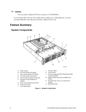
... removing network cables connected to system) F. Power supply J. Flex bay (optional DVD/CD-ROM drive/FDD module available) M. Backplane board I J K L O M N OM14080 A. System Components 8 Intel SR2300 Chassis Subassembly Product Guide Control panel C. Hard drive bay (one of six, accessory to system) G. Processor air duct L. If you install a NIC in the top slot of a CD-ROM drive. Server board (accessory to the card. Riser card assembly (low-profile) H. Front panel board Figure 1. Feature Summary System Components D C AB EFG H I . Intrusion switch...
... removing network cables connected to system) F. Power supply J. Flex bay (optional DVD/CD-ROM drive/FDD module available) M. Backplane board I J K L O M N OM14080 A. System Components 8 Intel SR2300 Chassis Subassembly Product Guide Control panel C. Hard drive bay (one of six, accessory to system) G. Processor air duct L. If you install a NIC in the top slot of a CD-ROM drive. Server board (accessory to the card. Riser card assembly (low-profile) H. Front panel board Figure 1. Feature Summary System Components D C AB EFG H I . Intrusion switch...

Product Guide
Page 12
... visible through BIOS, the LED state in a critical or nonrecoverable condition. Notes: 1 The Amber status takes precedence over the Green status. ID button Toggles on from running. 12 Intel SR2300 Chassis Subassembly Product Guide NIC 1 activity LED NIC 2 activity LED Continuous green light indicates activity between the system and the network to the Baseboard Management Controller (BMC), or the system board must be restored when the...
... visible through BIOS, the LED state in a critical or nonrecoverable condition. Notes: 1 The Amber status takes precedence over the Green status. ID button Toggles on from running. 12 Intel SR2300 Chassis Subassembly Product Guide NIC 1 activity LED NIC 2 activity LED Continuous green light indicates activity between the system and the network to the Baseboard Management Controller (BMC), or the system board must be restored when the...

Product Guide
Page 13
... system. Flex bay (1) C. When a drive fails, the SCSI backplane detects the failure, reports it, and powers down the failed drive. Peripherals The chassis provides external bays for mounting SCSI hard drives in the hard drive bays. Hard disk drive Figure 5. B A A D C E A. After the failed drive is removed and a new drive is inserted, there is a short wait before power is applied to the drive and the drive fault LED becomes a random blinking green light. Tape drive E.
... system. Flex bay (1) C. When a drive fails, the SCSI backplane detects the failure, reports it, and powers down the failed drive. Peripherals The chassis provides external bays for mounting SCSI hard drives in the hard drive bays. Hard disk drive Figure 5. B A A D C E A. After the failed drive is removed and a new drive is inserted, there is a short wait before power is applied to the drive and the drive fault LED becomes a random blinking green light. Tape drive E.
Product Guide
Page 14
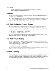
... The power subsystem supports implementation of remote management features including remote enable that permits power to minimize EMI. It is designed to be activated from a variety of sources. A second power supply module can be used with either configuration, the power supply provides 500 W of power and is turned off. The power supply provides 480W of power and is NOT hot swappable. For information on installation, see "Installing a DVD drive/FDD or CD-ROM drive...
... The power subsystem supports implementation of remote management features including remote enable that permits power to minimize EMI. It is designed to be activated from a variety of sources. A second power supply module can be used with either configuration, the power supply provides 500 W of power and is turned off. The power supply provides 480W of power and is NOT hot swappable. For information on installation, see "Installing a DVD drive/FDD or CD-ROM drive...

Product Guide
Page 19
... all peripheral devices connected to access components inside the server. The socket outlets must be flexible (harmonized) or VDE certified cordage to modify or use in your region. Turn off all AC power cords from the chassis or wall outlet. 3. Assembling the System 19 The power supply cords are not the exact type required. Only a technically qualified person should integrate and configure the server. It...
... all peripheral devices connected to access components inside the server. The socket outlets must be flexible (harmonized) or VDE certified cordage to modify or use in your region. Turn off all AC power cords from the chassis or wall outlet. 3. Assembling the System 19 The power supply cords are not the exact type required. Only a technically qualified person should integrate and configure the server. It...
Product Guide
Page 25
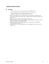
Install the Server Board CAUTION Do not install any server board support bumpers in a different order, component damage may occur. 1. If installed in the SR2300 chassis. Remove the server board from its packaging and antistatic bag. 3. System components must be installed in the order presented below the studs in the rear chassis wall. (Figure 10, A.) 2. Adjust board position so that the mounting holes rest securely on the chassis floor...
Install the Server Board CAUTION Do not install any server board support bumpers in a different order, component damage may occur. 1. If installed in the SR2300 chassis. Remove the server board from its packaging and antistatic bag. 3. System components must be installed in the order presented below the studs in the rear chassis wall. (Figure 10, A.) 2. Adjust board position so that the mounting holes rest securely on the chassis floor...
Product Guide
Page 34
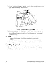
3. All cables from the power supply should route through the notch in cards, hard disk drives, a DVD/CD-ROM drive/floppy disk drive, and a tape drive. 34 Intel SR2300 Chassis Subassembly Product Guide A B OM14582 Figure 21. The following sections describe how to the matching connector. Ensure that the front panel cable is installed. 5. If it isn't installed, install the power supply air baffle. Route the cable between the memory connectors and the full height PCI riser, through the notch in...
3. All cables from the power supply should route through the notch in cards, hard disk drives, a DVD/CD-ROM drive/floppy disk drive, and a tape drive. 34 Intel SR2300 Chassis Subassembly Product Guide A B OM14582 Figure 21. The following sections describe how to the matching connector. Ensure that the front panel cable is installed. 5. If it isn't installed, install the power supply air baffle. Route the cable between the memory connectors and the full height PCI riser, through the notch in...

Product Guide
Page 35
...-length card has a card guide attached to the card. 1. PCI add-in cards must be installed on page 37) supports three Low Profile (LP) PCI add-in a Riser Card Assembling the System 35 The riser card on the chassis centerline (see Figure 24, B, on a riser card while the riser card is removed from the rear retention bracket (B) of the card's metal bracket in opening (C). If you may encounter difficulty removing network cables connected...
...-length card has a card guide attached to the card. 1. PCI add-in cards must be installed on page 37) supports three Low Profile (LP) PCI add-in a Riser Card Assembling the System 35 The riser card on the chassis centerline (see Figure 24, B, on a riser card while the riser card is removed from the rear retention bracket (B) of the card's metal bracket in opening (C). If you may encounter difficulty removing network cables connected...

Product Guide
Page 45
... peripheral devices connected to I/O connectors or ports on the front of the system. 4. All references to a chassis ground of the chassis. Tools and Supplies Needed • Antistatic wrist strap (recommended) Safety: Before You Remove the Cover Before removing the system cover to replace components in your server after it has been set up. Then unplug the AC power cord from the system or wall outlet. 3. 4 Working Inside Your Server...
... peripheral devices connected to I/O connectors or ports on the front of the system. 4. All references to a chassis ground of the chassis. Tools and Supplies Needed • Antistatic wrist strap (recommended) Safety: Before You Remove the Cover Before removing the system cover to replace components in your server after it has been set up. Then unplug the AC power cord from the system or wall outlet. 3. 4 Working Inside Your Server...

Product Guide
Page 47
Remove the hard drive from the carrier (A) by removing the four screws (D) from a Drive Bay 5. Working Inside Your Server 47 Pull the retention lever (A) toward you until the tab end (B) of the lever is free of the drive bay. Replacing Components Replacing a Hard Drive CAUTION To allow proper airflow and cooling during operation, all drive bays must contain either a carrier/drive or a carrier with air baffle installed. 1. Pull the...
Remove the hard drive from the carrier (A) by removing the four screws (D) from a Drive Bay 5. Working Inside Your Server 47 Pull the retention lever (A) toward you until the tab end (B) of the lever is free of the drive bay. Replacing Components Replacing a Hard Drive CAUTION To allow proper airflow and cooling during operation, all drive bays must contain either a carrier/drive or a carrier with air baffle installed. 1. Pull the...

Product Guide
Page 48
Install the new drive in any jumpers and/or switches on page 38). 9. Removing a Hard Drive from a Carrier 8. Reinstall a carrier/air baffle in the carrier and the carrier/drive into the drive bay (see "Installing a Hard Drive" on the drive according to the drive manufacturer's instructions. Set any bays where you are not reinstalling a carrier/drive. 48 Intel SR2300 Chassis Subassembly Product Guide 7. A B C D OM14110 Figure 31.
Install the new drive in any jumpers and/or switches on page 38). 9. Removing a Hard Drive from a Carrier 8. Reinstall a carrier/air baffle in the carrier and the carrier/drive into the drive bay (see "Installing a Hard Drive" on the drive according to the drive manufacturer's instructions. Set any bays where you are not reinstalling a carrier/drive. 48 Intel SR2300 Chassis Subassembly Product Guide 7. A B C D OM14110 Figure 31.

Product Guide
Page 49
... out to disengage the connector. (When you must first take the server out of service, turn off all peripheral devices connected to unlatch the module from the front of the flex bay. 5. B AB OM14111 Figure 32. Replacing a DVD/CD-ROM drive/FDD Module Working Inside Your Server 49 Replacing a DVD/CD-ROM drive/FDD Module CAUTION A DVD/CD-ROM drive/FDD module is NOT hot swappable. Remove the bezel from the...
... out to disengage the connector. (When you must first take the server out of service, turn off all peripheral devices connected to unlatch the module from the front of the flex bay. 5. B AB OM14111 Figure 32. Replacing a DVD/CD-ROM drive/FDD Module Working Inside Your Server 49 Replacing a DVD/CD-ROM drive/FDD Module CAUTION A DVD/CD-ROM drive/FDD module is NOT hot swappable. Remove the bezel from the...

Product Guide
Page 60
... PCI riser card. 13. Secure the board to work inside the system, observe the safety guidelines on page 45. 2. Install the fan module. 12. Install all cables to insert the LED light pipes into the front panel board. 9. Install the chassis cover. A B C OM14118 Figure 42. Install the new board in their bays. 14. Plug the USB and backplane cables back into the front panel holes. 7. Remove the cover from the front panel board (A). Removing the Front Panel Board 4. Remove the front panel board...
... PCI riser card. 13. Secure the board to work inside the system, observe the safety guidelines on page 45. 2. Install the fan module. 12. Install all cables to insert the LED light pipes into the front panel board. 9. Install the chassis cover. A B C OM14118 Figure 42. Install the new board in their bays. 14. Plug the USB and backplane cables back into the front panel holes. 7. Remove the cover from the front panel board (A). Removing the Front Panel Board 4. Remove the front panel board...
Product Guide
Page 62
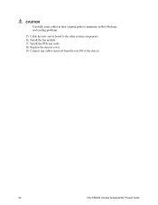
Install the PCI riser cards. 18. Connect any cables removed from the rear I/O of the chassis. 62 Intel SR2300 Chassis Subassembly Product Guide Install the fan module. 17. Cable the new server board to minimize airflow blockage and cooling problems. 15. Replace the chassis cover. 19. CAUTION Carefully route cables in their original paths to the other system components. 16.
Install the PCI riser cards. 18. Connect any cables removed from the rear I/O of the chassis. 62 Intel SR2300 Chassis Subassembly Product Guide Install the fan module. 17. Cable the new server board to minimize airflow blockage and cooling problems. 15. Replace the chassis cover. 19. CAUTION Carefully route cables in their original paths to the other system components. 16.

Product Guide
Page 74
... use the supplied AC power cord if it is considered the disconnect device to chassis ground of the system-any unpainted metal surface-when handling components. 6. Turn off all screws from the covers. 2. To do this product contains no user-serviceable parts. continued 74 Intel SR2300 Chassis Subassembly Product Guide The power cord(s) is not the exact type required. SAFETY STEPS: Whenever you remove the chassis covers to access the inside...
... use the supplied AC power cord if it is considered the disconnect device to chassis ground of the system-any unpainted metal surface-when handling components. 6. Turn off all screws from the covers. 2. To do this product contains no user-serviceable parts. continued 74 Intel SR2300 Chassis Subassembly Product Guide The power cord(s) is not the exact type required. SAFETY STEPS: Whenever you remove the chassis covers to access the inside...
Product Guide
Page 85
... was purchased from design defects or errors known as "errata". For all other locations, the warranty excludes all of its option, will be free from an Intel authorized distributor. Intel will have a reasonable time to make repairs or to replace Product or to repair or replace the Product. D Warranty Limited Warranty for Intel® Chassis Subassembly Products Intel warrants that the Products (defined herein...
... was purchased from design defects or errors known as "errata". For all other locations, the warranty excludes all of its option, will be free from an Intel authorized distributor. Intel will have a reasonable time to make repairs or to replace Product or to repair or replace the Product. D Warranty Limited Warranty for Intel® Chassis Subassembly Products Intel warrants that the Products (defined herein...


