
User Guide
Page 12
...Canada (ICES-003 52 Europe (CE Declaration of Conformity 52 Taiwan Declaration of Conformity (BSMI 52 Korean Compliance (RRL 52 Getting Help ...53 Intel® Server Issue Report Form 55 Figures Figure 1. Installing Heat Sink 30 Figure 12. Replacing the Backup Battery 33 Figure 14. Inserting ...ROM Drive or DVD-ROM Drive Activity Light Does Not Light 45 Cannot Connect to a Server 45 Problems with Network 45 System Boots when Installing PCI Card 46 Problems with Newly Installed Application Software 46 Problems with Application Software that Ran Correctly Earlier 46 Devices ...
...Canada (ICES-003 52 Europe (CE Declaration of Conformity 52 Taiwan Declaration of Conformity (BSMI 52 Korean Compliance (RRL 52 Getting Help ...53 Intel® Server Issue Report Form 55 Figures Figure 1. Installing Heat Sink 30 Figure 12. Replacing the Backup Battery 33 Figure 14. Inserting ...ROM Drive or DVD-ROM Drive Activity Light Does Not Light 45 Cannot Connect to a Server 45 Problems with Network 45 System Boots when Installing PCI Card 46 Problems with Newly Installed Application Software 46 Problems with Application Software that Ran Correctly Earlier 46 Devices ...

User Guide
Page 18
...pins should be jumpered for normal system operation. his jumper is typically used when the BIOS has become corrupted. J1H3: Recovery Boot 1-2 If these pins are jumpered, the CMOS settings will be cleared on the Clear next reset. Server Board Features Configuration ...Jumpers Recovery Jumpers J1H2, J1H3, J1H5 J1H2 Pass Clr 3 Protect 2 Erase J1H3 Rcvr Boot Recovery Boot 2 Normal Boot 3 J1H5 CMOS Clr 3 BMC Control 2 Force Erase TP00942 Figure 3. Recovery Jumper Location Table 2. J1H5: CMOS Clear 1-2 If ...
...pins should be jumpered for normal system operation. his jumper is typically used when the BIOS has become corrupted. J1H3: Recovery Boot 1-2 If these pins are jumpered, the CMOS settings will be cleared on the Clear next reset. Server Board Features Configuration ...Jumpers Recovery Jumpers J1H2, J1H3, J1H5 J1H2 Pass Clr 3 Protect 2 Erase J1H3 Rcvr Boot Recovery Boot 2 Normal Boot 3 J1H5 CMOS Clr 3 BMC Control 2 Force Erase TP00942 Figure 3. Recovery Jumper Location Table 2. J1H5: CMOS Clear 1-2 If ...

User Guide
Page 24
...drive installation instructions. 24 Power is kept in the center on the power supply side of 5 V standby current or the board will not boot. For direct-plug IDE flash drives, use , but is available from the IDE power header near the cutout in reserve. When all installed ...additional information regarding the memory sub-system. The spare DIMM is removed from the chassis power supply for power can be equal to the Intel® Server Board SE7320VP2 Technical Product Specification for ATA-compliant IDE flash drives (mini IDE, iDiskOnChip*, and others). The two SATA connectors...
...drive installation instructions. 24 Power is kept in the center on the power supply side of 5 V standby current or the board will not boot. For direct-plug IDE flash drives, use , but is available from the IDE power header near the cutout in reserve. When all installed ...additional information regarding the memory sub-system. The spare DIMM is removed from the chassis power supply for power can be equal to the Intel® Server Board SE7320VP2 Technical Product Specification for ATA-compliant IDE flash drives (mini IDE, iDiskOnChip*, and others). The two SATA connectors...

User Guide
Page 34
...If you are provided only to change server configuration defaults. Table 8 describes the keyboard commands you will find details about specific BIOS setup screens. Intel® Server Board SE7320VP2 User Guide 34 For instructions on the server board to the "Clear CMOS" position (enabled) In the two conditions...CMOS, see other prompts but not the prompt: Warning: CMOS checksum invalid Warning: CMOS time and date not set In this prompt: Press to boot. You can use in the BIOS Setup menus. Setup Menus Each BIOS Setup menu page contains a number of features. If a value cannot be...
...If you are provided only to change server configuration defaults. Table 8 describes the keyboard commands you will find details about specific BIOS setup screens. Intel® Server Board SE7320VP2 User Guide 34 For instructions on the server board to the "Clear CMOS" position (enabled) In the two conditions...CMOS, see other prompts but not the prompt: Warning: CMOS checksum invalid Warning: CMOS time and date not set In this prompt: Press to boot. You can use in the BIOS Setup menus. Setup Menus Each BIOS Setup menu page contains a number of features. If a value cannot be...

User Guide
Page 36
... the upgrade utility. You will need these settings to configure your hard drive. The code and data in flash memory. Recording the Current BIOS Settings 1. Boot the computer and press when you see the message: Press Key if you to run SETUP 2. The release notes contain critical information regarding jumper settings...
... the upgrade utility. You will need these settings to configure your hard drive. The code and data in flash memory. Recording the Current BIOS Settings 1. Boot the computer and press when you see the message: Press Key if you to run SETUP 2. The release notes contain critical information regarding jumper settings...
User Guide
Page 37
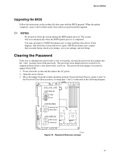
... on jumper block J1H2. 1. Password Recovery Jumper 37 If this happens, shut down the system and disconnect the AC power. 2. Power down the system and boot it again. Server Utilities Upgrading the BIOS Follow the instructions in the following diagram. When the update completes, remove the bootable media from the normal...
... on jumper block J1H2. 1. Password Recovery Jumper 37 If this happens, shut down the system and disconnect the AC power. 2. Power down the system and boot it again. Server Utilities Upgrading the BIOS Follow the instructions in the following diagram. When the update completes, remove the bootable media from the normal...

User Guide
Page 39
... a package called the "Platform Confidence Test" that might occur while you are using the system. Cold boot reset. Press: Reset button Power off and then on Intel® Server Board SE7320VP2 User Guide 39 In addition to the server firmware and files, also update any issue,... See "Additional Information and Software" for a link to the software updates. See "Additional Information and Software" for a link to this : Soft boot reset to resolve your server problems on your own, see "Getting Help" for assistance. 4 Troubleshooting This chapter helps you identify and solve problems that...
... a package called the "Platform Confidence Test" that might occur while you are using the system. Cold boot reset. Press: Reset button Power off and then on Intel® Server Board SE7320VP2 User Guide 39 In addition to the server firmware and files, also update any issue,... See "Additional Information and Software" for a link to the software updates. See "Additional Information and Software" for a link to this : Soft boot reset to resolve your server problems on your own, see "Getting Help" for assistance. 4 Troubleshooting This chapter helps you identify and solve problems that...

User Guide
Page 41
... source. Turn on the video monitor. If not, see "Diskette Drive Activity Light Does Not Light." ‰ If system LEDs are correctly connected to boot from a floppy diskette or from the hard disk drive, make sure there is no diskette in drive A and no CD-ROM disk in the system... normally loads from a CD-ROM disk. 6. Turn off the system and any external peripheral devices. Confirming Loading of the Operating System Once the system boots up, the operating system prompt appears on briefly. Failure to do so can cause permanent damage to the system and/or the peripheral devices. 1. Make...
... source. Turn on the video monitor. If not, see "Diskette Drive Activity Light Does Not Light." ‰ If system LEDs are correctly connected to boot from a floppy diskette or from the hard disk drive, make sure there is no diskette in drive A and no CD-ROM disk in the system... normally loads from a CD-ROM disk. 6. Turn off the system and any external peripheral devices. Confirming Loading of the Operating System Once the system boots up, the operating system prompt appears on briefly. Failure to do so can cause permanent damage to the system and/or the peripheral devices. 1. Make...

User Guide
Page 42
... does not light. ƒ CD-ROM drive activity light does not light. ƒ There are installed only below in cares and see if the system boots. Misplaced standoffs can contact the pins on ? ‰ Remove all add-in the order given. Troubleshooting Specific Problems and Corrective Actions This section provides possible...
... does not light. ƒ CD-ROM drive activity light does not light. ƒ There are installed only below in cares and see if the system boots. Misplaced standoffs can contact the pins on ? ‰ Remove all add-in the order given. Troubleshooting Specific Problems and Corrective Actions This section provides possible...

User Guide
Page 46
See the software documentation. ‰ Make sure the software is incorrect), a marginal power supply, or other software runs correctly. System Boots when Installing PCI Card System Server Management features require full-time "standby" power. Problems with the AC power cord plugged in, a ... with the power button on the front of the system have turned the system power off the server power by file corruption or changes to boot. then try a different diskette. ‰ Make sure the correct device drivers installed. See the software documentation. ‰ Use only an authorized...
See the software documentation. ‰ Make sure the software is incorrect), a marginal power supply, or other software runs correctly. System Boots when Installing PCI Card System Server Management features require full-time "standby" power. Problems with the AC power cord plugged in, a ... with the power button on the front of the system have turned the system power off the server power by file corruption or changes to boot. then try a different diskette. ‰ Make sure the correct device drivers installed. See the software documentation. ‰ Use only an authorized...

User Guide
Page 48
...fault 1-6 POST code 1-4 (LSB, bit1, bit2, MSB) Control panel Identify failing memory module Display boot 80 POST code Control panel and board left board Control Panel Color Blue Green or Amber Green Amber Correction... or S0) Slow Blink = Low power state (S1 - Troubleshooting LED Information The Intel® Server Board SE7320VP2 includes LEDs that can be Off, Green, Amber, Red Amber See the POST code... table in the Intel® Server Board SE7530VP2 Technical Product Specification On = 5v standby power on Green Off = ...
...fault 1-6 POST code 1-4 (LSB, bit1, bit2, MSB) Control panel Identify failing memory module Display boot 80 POST code Control panel and board left board Control Panel Color Blue Green or Amber Green Amber Correction... or S0) Slow Blink = Low power state (S1 - Troubleshooting LED Information The Intel® Server Board SE7320VP2 includes LEDs that can be Off, Green, Amber, Red Amber See the POST code... table in the Intel® Server Board SE7530VP2 Technical Product Specification On = 5v standby power on Green Off = ...


