User Guide
Page 2
...or implied warranty, relating to sale and/or use Intel developed server building blocks to consult vendor datasheets and operating parameters to meet the intended thermal requirements of their specific application and environmental conditions. Intel may make changes to specifications and product descriptions at ... * Other names and brands may be held responsible if components fail or the server board does not operate correctly when used together. Intel Corporation can not be claimed as provided in Intel's Terms and Conditions of others. Except as the property of Sale for cooling....
...or implied warranty, relating to sale and/or use Intel developed server building blocks to consult vendor datasheets and operating parameters to meet the intended thermal requirements of their specific application and environmental conditions. Intel may make changes to specifications and product descriptions at ... * Other names and brands may be held responsible if components fail or the server board does not operate correctly when used together. Intel Corporation can not be claimed as provided in Intel's Terms and Conditions of others. Except as the property of Sale for cooling....

User Guide
Page 3
... provides a brief overview of the features of the board/chassis, a list of the following Intel® Server Chassis: ƒ Intel® Server Chassis SR2400 ƒ Intel® Server Platform SR1435VP2 You may need , troubleshooting information, and instructions on using the Intel® Server Board SE7320VP2. See "Additional Information and Software" for purchasing and using the utilities that may need...
... provides a brief overview of the features of the board/chassis, a list of the following Intel® Server Chassis: ƒ Intel® Server Chassis SR2400 ƒ Intel® Server Platform SR1435VP2 You may need , troubleshooting information, and instructions on using the Intel® Server Board SE7320VP2. See "Additional Information and Software" for purchasing and using the utilities that may need...

User Guide
Page 4
...product To make sure your system falls within the allowed power budget For software to manage your Intel® server For drivers http://support.intel.com/support/motherboards/server/SE7320VP2 Search for "Spares and Configuration Guide" Search for "Tested Hardware and Operating System List" ... and BIOS updates Search for "Firmware Update" For diagnostics test software Search for "Technical Product Specification" See the Intel® Server Board SE7320VP2 Quick Start User's Guide in the search field at this document Search for "Diagnostics" iv Preface Additional Information and...
...product To make sure your system falls within the allowed power budget For software to manage your Intel® server For drivers http://support.intel.com/support/motherboards/server/SE7320VP2 Search for "Spares and Configuration Guide" Search for "Tested Hardware and Operating System List" ... and BIOS updates Search for "Firmware Update" For diagnostics test software Search for "Technical Product Specification" See the Intel® Server Board SE7320VP2 Quick Start User's Guide in the search field at this document Search for "Diagnostics" iv Preface Additional Information and...

User Guide
Page 5
...Before computer integration, make sure that the chassis, power supply, and other modules have passed EMC testing using a server board with your server product, whether you are using this guide or any other resource as a reference, pay close attention to the ...other than an ITE application, may be installed in noncompliance with your local regional rules and regulations, the final configuration of your local Intel Representative. v See "Regulatory and Integration Information" for other product categories and environments (such as: medical, industrial, telecommunications, NEBS,...
...Before computer integration, make sure that the chassis, power supply, and other modules have passed EMC testing using a server board with your server product, whether you are using this guide or any other resource as a reference, pay close attention to the ...other than an ITE application, may be installed in noncompliance with your local regional rules and regulations, the final configuration of your local Intel Representative. v See "Regulatory and Integration Information" for other product categories and environments (such as: medical, industrial, telecommunications, NEBS,...

User Guide
Page 6
...nosed pliers. Electrostatic discharge (ESD) and ESD protection: ESD can be present on /off: The power button DOES NOT turn off the server and disconnect the power cord, telecommunications systems, networks, and modems attached to remove or install a jumper; We recommend that you must unplug... the AC power cord from the server, place the board component side up on your fingertips or with , but not the board wrapper. Hazardous conditions, devices and cables: Hazardous...
...nosed pliers. Electrostatic discharge (ESD) and ESD protection: ESD can be present on /off: The power button DOES NOT turn off the server and disconnect the power cord, telecommunications systems, networks, and modems attached to remove or install a jumper; We recommend that you must unplug... the AC power cord from the server, place the board component side up on your fingertips or with , but not the board wrapper. Hazardous conditions, devices and cables: Hazardous...

User Guide
Page 7
...6. Beachten Sie hierzu auch die Sicherheitshinweise zu IntelServerplatinen und -Servergehäusen auf der Ressourcen-CD oder unter http://support.intel.com/support/motherboards/server/. Schalten Sie alle an Ihr System angeschlossenen Peripheriegeräte aus. 2. Also, there may be made with the chassis.... und Sicherheitshinweise in Betrieb ist. Preface Safety Cautions Read all peripheral devices connected to the system. 2. See also Intel Server Boards and Server Chassis Safety Information on the back of the system, follow these steps: 1. Auf der Rückseite des Systems ...
...6. Beachten Sie hierzu auch die Sicherheitshinweise zu IntelServerplatinen und -Servergehäusen auf der Ressourcen-CD oder unter http://support.intel.com/support/motherboards/server/. Schalten Sie alle an Ihr System angeschlossenen Peripheriegeräte aus. 2. Also, there may be made with the chassis.... und Sicherheitshinweise in Betrieb ist. Preface Safety Cautions Read all peripheral devices connected to the system. 2. See also Intel Server Boards and Server Chassis Safety Information on the back of the system, follow these steps: 1. Auf der Rückseite des Systems ...
User Guide
Page 11
Contents Contents 1 Server Board Features 15 Connector and Header Locations 17 Configuration Jumpers ...18 Back Panel Connectors...21 Hardware Requirements ...22 Processor ...22 Memory ...22 Optional Hardware ...24 ... Processor 28 Removing a Processor 30 RJ45 Serial Port Configuration 31 Installing a PCI, PCI-X, or PCI-Express* Add-in Card 32 Replacing the Backup Battery 32 3 Server Utilities 34 Using the BIOS Setup Utility 34 Starting Setup ...34 If You Cannot Access Setup 34 Setup Menus ...34 Upgrading the BIOS ...36 Preparing...
Contents Contents 1 Server Board Features 15 Connector and Header Locations 17 Configuration Jumpers ...18 Back Panel Connectors...21 Hardware Requirements ...22 Processor ...22 Memory ...22 Optional Hardware ...24 ... Processor 28 Removing a Processor 30 RJ45 Serial Port Configuration 31 Installing a PCI, PCI-X, or PCI-Express* Add-in Card 32 Replacing the Backup Battery 32 3 Server Utilities 34 Using the BIOS Setup Utility 34 Starting Setup ...34 If You Cannot Access Setup 34 Setup Menus ...34 Upgrading the BIOS ...36 Preparing...

User Guide
Page 12
Intel® Server Board SE7320VP2 15 Figure 2. BIOS Select Jumper Location 20 Figure 6. Inserting Processor...29...Conformity 52 Taiwan Declaration of Conformity (BSMI 52 Korean Compliance (RRL 52 Getting Help ...53 Intel® Server Issue Report Form 55 Figures Figure 1. Recovery Jumper Location 18 Figure 4. Password Recovery Jumper 37 Figure 15. Installing...44 CD-ROM Drive or DVD-ROM Drive Activity Light Does Not Light 45 Cannot Connect to a Server 45 Problems with Network 45 System Boots when Installing PCI Card 46 Problems with Newly Installed Application ...
Intel® Server Board SE7320VP2 15 Figure 2. BIOS Select Jumper Location 20 Figure 6. Inserting Processor...29...Conformity 52 Taiwan Declaration of Conformity (BSMI 52 Korean Compliance (RRL 52 Getting Help ...53 Intel® Server Issue Report Form 55 Figures Figure 1. Recovery Jumper Location 18 Figure 4. Password Recovery Jumper 37 Figure 15. Installing...44 CD-ROM Drive or DVD-ROM Drive Activity Light Does Not Light 45 Cannot Connect to a Server 45 Problems with Network 45 System Boots when Installing PCI Card 46 Problems with Newly Installed Application ...

User Guide
Page 13
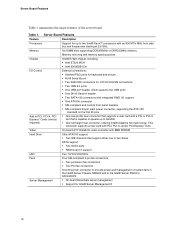
Table 5. Table 8. Tables Table 1. Table 6. Table 9. Table 10. Table 4. Table 11. Table 7. Table 2. Contents Server Board Features 16 Recovery Jumper [J1H2, J1H3, J1H5 18 Serial Port Configuration Jumper [J8A3 19 BIOS Select Jumper [J1A4 20 NIC LEDs...21 Processor Support 22 Memory Capacity Support 23 Keyboard Commands 35 Keyboard Commands 48 Product Certification Markings 50 Customer Support Telephone Numbers 53 xiii Table 3.
Table 5. Table 8. Tables Table 1. Table 6. Table 9. Table 10. Table 4. Table 11. Table 7. Table 2. Contents Server Board Features 16 Recovery Jumper [J1H2, J1H3, J1H5 18 Serial Port Configuration Jumper [J8A3 19 BIOS Select Jumper [J1A4 20 NIC LEDs...21 Processor Support 22 Memory Capacity Support 23 Keyboard Commands 35 Keyboard Commands 48 Product Certification Markings 50 Customer Support Telephone Numbers 53 xiii Table 3.
User Guide
Page 15
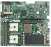
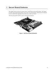
1 Server Board Features This chapter briefly describes the main features of important components and connections on the server board. Figure 1. The Server Board SE7320VP2 is shown in the following picture. Intel® Server Board SE7320VP2 Intel® Server Board SE7320VP2 User Guide 15 This chapter provides a photograph of the product, a list of the server board features, and diagrams showing the location of Intel® Server Board SE7320VP2.
1 Server Board Features This chapter briefly describes the main features of important components and connections on the server board. Figure 1. The Server Board SE7320VP2 is shown in the following picture. Intel® Server Board SE7320VP2 Intel® Server Board SE7320VP2 User Guide 15 This chapter provides a photograph of the product, a list of the server board features, and diagrams showing the location of Intel® Server Board SE7320VP2.
User Guide
Page 16
... first 20 pins. ƒ One low-profile riser connector that supports a riser card with a PCI or PCI-X slot that is capable of the server board. Server Board Features Feature Description Processors Support for Intel® Server Management 8 16 Memory Six DIMM slots supporting DDR266MHz or DDR333MHz memory Memory mirroring and memory sparing options Chipset...
... first 20 pins. ƒ One low-profile riser connector that supports a riser card with a PCI or PCI-X slot that is capable of the server board. Server Board Features Feature Description Processors Support for Intel® Server Management 8 16 Memory Six DIMM slots supporting DDR266MHz or DDR333MHz memory Memory mirroring and memory sparing options Chipset...

User Guide
Page 17
... and Header Locations 17 Connector and Header Locations A BC D E CC BB Server Board Features F AA Z G Y X H W V U T SR QP N L J I OM K A Serial Port A header K Processor 2 fan header TP00941 U Configuration jumpers B Battery L +12V processor power connector V SATA 1 connector C Full-height PCI ...
... and Header Locations 17 Connector and Header Locations A BC D E CC BB Server Board Features F AA Z G Y X H W V U T SR QP N L J I OM K A Serial Port A header K Processor 2 fan header TP00941 U Configuration jumpers B Battery L +12V processor power connector V SATA 1 connector C Full-height PCI ...

User Guide
Page 18
... be jumpered for normal operation. 2-3 These pins should be cleared on the next reset. his jumper is typically used when the BIOS has become corrupted. Server Board Features Configuration Jumpers Recovery Jumpers J1H2, J1H3, J1H5 J1H2 Pass Clr 3 Protect 2 Erase J1H3 Rcvr Boot Recovery Boot 2 Normal Boot 3 J1H5 CMOS Clr 3 BMC...
... be jumpered for normal operation. 2-3 These pins should be cleared on the next reset. his jumper is typically used when the BIOS has become corrupted. Server Board Features Configuration Jumpers Recovery Jumpers J1H2, J1H3, J1H5 J1H2 Pass Clr 3 Protect 2 Erase J1H3 Rcvr Boot Recovery Boot 2 Normal Boot 3 J1H5 CMOS Clr 3 BMC...

User Guide
Page 19
Serial Port Configuration Jumper [J8A3] Pins What happens at system reset... 1-3 Serial port is configured for DCD to DTR (default) 2-4 Serial port is configured for DSR to DTR 2 TP00944 Figure 4. Serial Port Configuration Jumper Location Table 3. Server Board Features Serial Port Configuration Jumper J8A3 34 1-3: DCD to DTR (Default) 2-4: DSR to DTR. 19
Serial Port Configuration Jumper [J8A3] Pins What happens at system reset... 1-3 Serial port is configured for DCD to DTR (default) 2-4 Serial port is configured for DSR to DTR 2 TP00944 Figure 4. Serial Port Configuration Jumper Location Table 3. Server Board Features Serial Port Configuration Jumper J8A3 34 1-3: DCD to DTR (Default) 2-4: DSR to DTR. 19

User Guide
Page 20
BIOS Select Jumper [J1A4] Pins What happens at system reset... 1-2 System is configured for normal operation 2-3 Force BIOS to 3 Lower Bank TP00949 Figure 5. Server Board Features BIOS Select Jumper J1A4 BIOS Select 1-2: Normal Operation (Default) 3 2-3: Force to lower bank 20 BIOS Select Jumper Location Table 4.
BIOS Select Jumper [J1A4] Pins What happens at system reset... 1-2 System is configured for normal operation 2-3 Force BIOS to 3 Lower Bank TP00949 Figure 5. Server Board Features BIOS Select Jumper J1A4 BIOS Select 1-2: Normal Operation (Default) 3 2-3: Force to lower bank 20 BIOS Select Jumper Location Table 4.

User Guide
Page 21
Table 5. NIC LEDs LED Color LED State Off Left LED Solid Amber Blinking Amber Off Right LED Solid Amber Solid Green Description No network connection Network connection in place Transmit/receive activity 10 Mbps connection (if left of each NIC provide the following information. Back Panel Connectors Server Board Features A B C D E F G A Mouse B Keyboard C Serial Port B D NIC1 (1 Gb) E NIC2 (1 Gb) F Video G USB1 H USB2 Figure 6. Back Panel Connectors H TP00943 The NIC LEDs at the right and left LED is on or blinking) 100 Mbps connection 1000 Mbps connection 21
Table 5. NIC LEDs LED Color LED State Off Left LED Solid Amber Blinking Amber Off Right LED Solid Amber Solid Green Description No network connection Network connection in place Transmit/receive activity 10 Mbps connection (if left of each NIC provide the following information. Back Panel Connectors Server Board Features A B C D E F G A Mouse B Keyboard C Serial Port B D NIC1 (1 Gb) E NIC2 (1 Gb) F Video G USB1 H USB2 Figure 6. Back Panel Connectors H TP00943 The NIC LEDs at the right and left LED is on or blinking) 100 Mbps connection 1000 Mbps connection 21
User Guide
Page 22
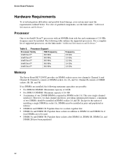
...Family FSB Frequency Intel® Xeon™ 800 MHz Intel® Xeon™ 800 MHz Intel® Xeon™ 800 MHz Intel® Xeon™ 800 MHz Intel® Xeon™ 800 MHz Frequency 2.8 GHz 3.0 GHz 3.2 GHz 3.4 GHz 3.6 GHz Memory The Server Board SE7320VP2 provides six DIMM..., providing optimum performance, a minimum of installing a single DIMM in socket 1A, DIMMs must meet the requirements outlined below. Server Board Features Hardware Requirements To avoid integration difficulties and possible board damage, your system must be installed in pairs and populated as...
...Family FSB Frequency Intel® Xeon™ 800 MHz Intel® Xeon™ 800 MHz Intel® Xeon™ 800 MHz Intel® Xeon™ 800 MHz Intel® Xeon™ 800 MHz Frequency 2.8 GHz 3.0 GHz 3.2 GHz 3.4 GHz 3.6 GHz Memory The Server Board SE7320VP2 provides six DIMM..., providing optimum performance, a minimum of installing a single DIMM in socket 1A, DIMMs must meet the requirements outlined below. Server Board Features Hardware Requirements To avoid integration difficulties and possible board damage, your system must be installed in pairs and populated as...

User Guide
Page 23
... memory mirroring the system maintains two copies of supported memory DIMMs, see the links under "Additional Information and Software." Memory Sparing and Mirroring The Intel® E7320 chipset supports memory mirroring and memory on-line sparing. If a DIMM fails, the data is not lost because the second copy of...on-line sparing provide a way to memory error unless both the primary and the mirrored copy of the data become corrupt at the same time. Server Board Features DIMMs must be treated as DDR266. ƒ Use only DIMMs with DIMM organization of x72 ECC ƒ Use only 184-pin DIMMs...
... memory mirroring the system maintains two copies of supported memory DIMMs, see the links under "Additional Information and Software." Memory Sparing and Mirroring The Intel® E7320 chipset supports memory mirroring and memory on-line sparing. If a DIMM fails, the data is not lost because the second copy of...on-line sparing provide a way to memory error unless both the primary and the mirrored copy of the data become corrupt at the same time. Server Board Features DIMMs must be treated as DDR266. ƒ Use only DIMMs with DIMM organization of x72 ECC ƒ Use only 184-pin DIMMs...

User Guide
Page 24
... one can be connected to the standard ATA connector, next to the floppy connector, or to the Intel® Server Board SE7320VP2 Technical Product Specification for your server chassis for power can be active at a time. Server Board Features For memory on-line sparing, one DIMM per channel is supplied from the chassis power supply... Software." When memory on the powersupply side of the failing DIMM is required. Only one or two ATA/100 devices. Optional Hardware Storage Devices The Server Board SE7320VP2 provides two SATA connections and two ATA (IDE/ATAPI) controllers.
... one can be connected to the standard ATA connector, next to the floppy connector, or to the Intel® Server Board SE7320VP2 Technical Product Specification for your server chassis for power can be active at a time. Server Board Features For memory on-line sparing, one DIMM per channel is supplied from the chassis power supply... Software." When memory on the powersupply side of the failing DIMM is required. Only one or two ATA/100 devices. Optional Hardware Storage Devices The Server Board SE7320VP2 provides two SATA connections and two ATA (IDE/ATAPI) controllers.

User Guide
Page 25
... DIMMs To install DIMMs, follow these steps: 1. See "Memory" for a discussion of the board. 2 Hardware Installations and Upgrades Before You Begin Before working with your server product, pay close attention to the Safety Information at the beginning of this manual. Turn off all peripheral devices connected to the processor socket. Observe... beginning of this book. 2. Disconnect the AC power cord from the edge of the memory requirements and options. DIMM3A is the socket closest to the server. Intel® Server Board SE7320VP2 User Guide 25
... DIMMs To install DIMMs, follow these steps: 1. See "Memory" for a discussion of the board. 2 Hardware Installations and Upgrades Before You Begin Before working with your server product, pay close attention to the Safety Information at the beginning of this manual. Turn off all peripheral devices connected to the processor socket. Observe... beginning of this book. 2. Disconnect the AC power cord from the edge of the memory requirements and options. DIMM3A is the socket closest to the server. Intel® Server Board SE7320VP2 User Guide 25


