User Guide
Page 3
... installing or replacing components such as the memory, processor, PCI card, and the battery, among other components you will also find BIOS error messages and POST code messages. For the latest version of these server boards. Chapter 3 provides instructions on how to help you for purchasing and using the utilities that are responsible for a link to reset the password or CMOS. Intel Server Board SE7320SP2 / SE7525GP2 User Guide iii Use this chapter for step-bystep instructions...
... installing or replacing components such as the memory, processor, PCI card, and the battery, among other components you will also find BIOS error messages and POST code messages. For the latest version of these server boards. Chapter 3 provides instructions on how to help you for purchasing and using the utilities that are responsible for a link to reset the password or CMOS. Intel Server Board SE7320SP2 / SE7525GP2 User Guide iii Use this chapter for step-bystep instructions...

User Guide
Page 4
..., including BIOS settings and chipset information If you need to install it For virtual system tours and interactive repair information Use this Document or Software Technical Product Specification Intel® Server Board SE7320SP2 Quick Start User's Guide in the product box Intel® Server Board SE7525GP2 Quick Start User's Guide in the product box A link to search "This Product." These files are available at http://support.intel.com/support/motherboards/server/SE7320SP2/ http://support.intel.com/support/motherboards/server/SE7320SP2/ Unless...
..., including BIOS settings and chipset information If you need to install it For virtual system tours and interactive repair information Use this Document or Software Technical Product Specification Intel® Server Board SE7320SP2 Quick Start User's Guide in the product box Intel® Server Board SE7525GP2 Quick Start User's Guide in the product box A link to search "This Product." These files are available at http://support.intel.com/support/motherboards/server/SE7320SP2/ http://support.intel.com/support/motherboards/server/SE7320SP2/ Unless...

User Guide
Page 6
... wide sides. Label and disconnect all peripheral devices connected to chassis ground any of the instructions. ESD and handling boards: Always handle boards carefully. Use a conductive foam pad if available but not squeeze, the pliers or other parts. Installing or removing jumpers: A jumper is not available, provide some electrostatic discharge (ESD) protection by pressing the power button. 3. Some jumpers have such a tab, take care when...
... wide sides. Label and disconnect all peripheral devices connected to chassis ground any of the instructions. ESD and handling boards: Always handle boards carefully. Use a conductive foam pad if available but not squeeze, the pliers or other parts. Installing or removing jumpers: A jumper is not available, provide some electrostatic discharge (ESD) protection by pressing the power button. 3. Some jumpers have such a tab, take care when...

User Guide
Page 11
... Removing the Processor 28 Installing a PCI Card ...28 Replacing the Backup Battery 29 3 Server Utilities 31 Upgrading the BIOS ...32 Preparing for the Upgrade 32 Upgrading the BIOS ...33 Changing the BIOS Language 34 Recovering the BIOS ...35 Manually Recovering the BIOS 35 Clearing the CMOS ...35 Clearing the Password ...36 4 Troubleshooting 37 Resetting the System ...37 Problems following Initial System Installation 37 First Steps Checklist...37 Hardware Diagnostic Testing 38 Verifying Proper Operation of Key System Lights...
... Removing the Processor 28 Installing a PCI Card ...28 Replacing the Backup Battery 29 3 Server Utilities 31 Upgrading the BIOS ...32 Preparing for the Upgrade 32 Upgrading the BIOS ...33 Changing the BIOS Language 34 Recovering the BIOS ...35 Manually Recovering the BIOS 35 Clearing the CMOS ...35 Clearing the Password ...36 4 Troubleshooting 37 Resetting the System ...37 Problems following Initial System Installation 37 First Steps Checklist...37 Hardware Diagnostic Testing 38 Verifying Proper Operation of Key System Lights...

User Guide
Page 13
...19 BIOS Select Jumper [J29 19 NIC LEDs...20 Keyboard Commands 31 BIOS Error Messages 47 Beep Codes 48 BIOS Recovery Beep Codes 49 Product Certification Markings 52 Intel Server Board SE7320SP2 / SE7525GP2 User Guide 13 Intel Server Board SE7320SP2 / SE7525GP2 Layout 18 Figure 3. Table 3. Table 7. Table 9. Configuration and BIOS Select Jumper Locations 19 Figure 4. Installing Heat Sink over Processor 27 Figure 9. Table 5. Back Panel Connectors 20 Figure 5. Contents Figures Figure 1. Table 8. Opening Socket Lever and Attaching Processor 26 Figure 8. Replacing the...
...19 BIOS Select Jumper [J29 19 NIC LEDs...20 Keyboard Commands 31 BIOS Error Messages 47 Beep Codes 48 BIOS Recovery Beep Codes 49 Product Certification Markings 52 Intel Server Board SE7320SP2 / SE7525GP2 User Guide 13 Intel Server Board SE7320SP2 / SE7525GP2 Layout 18 Figure 3. Table 3. Table 7. Table 9. Configuration and BIOS Select Jumper Locations 19 Figure 4. Installing Heat Sink over Processor 27 Figure 9. Table 5. Back Panel Connectors 20 Figure 5. Contents Figures Figure 1. Table 8. Opening Socket Lever and Attaching Processor 26 Figure 8. Replacing the...

User Guide
Page 16
...Memory Chipset Support for two Intel® Xeon™ processors in two 604-pin Intel Xeon processor sockets with support for: ƒ Advanced Configuration and Power Interface (ACPI) ƒ 8 megabit symmetrical flash memory ƒ Support for SMBIOS Power Management Server Management Leadership Technologies Support for 10/100/1000 Mbits/sec Ethernet LAN connectivity (on some FRU devices (processors, power) ƒ Port-80 Diagnostic LEDs displaying POST Codes Intel Server Board SE7320SP2 / SE7525GP2 User Guide 16 one 32-bit/33 MHz PCI, 5 V) with five bus connectors: ƒ One x8 PCI...
...Memory Chipset Support for two Intel® Xeon™ processors in two 604-pin Intel Xeon processor sockets with support for: ƒ Advanced Configuration and Power Interface (ACPI) ƒ 8 megabit symmetrical flash memory ƒ Support for SMBIOS Power Management Server Management Leadership Technologies Support for 10/100/1000 Mbits/sec Ethernet LAN connectivity (on some FRU devices (processors, power) ƒ Port-80 Diagnostic LEDs displaying POST Codes Intel Server Board SE7320SP2 / SE7525GP2 User Guide 16 one 32-bit/33 MHz PCI, 5 V) with five bus connectors: ƒ One x8 PCI...

User Guide
Page 17
... symmetrical flash memory ƒ Support for SMBIOS Power Management Support for ACPI: ƒ Wake on USB, PCI, RS-232, PS/2, LAN, and control panel Server Management Leadership Technologies Intel Server Management 8.0 support via the National* Semiconductor PC87431M integrated management controller providing onboard platform instrumentation. ƒ Light Guided Diagnostics on the back panel with an additional internal header, which provides support for two additional USB ports for RAID 0 and 1 ƒ One floppy drive interface with 8 MB of the Server Board...
... symmetrical flash memory ƒ Support for SMBIOS Power Management Support for ACPI: ƒ Wake on USB, PCI, RS-232, PS/2, LAN, and control panel Server Management Leadership Technologies Intel Server Management 8.0 support via the National* Semiconductor PC87431M integrated management controller providing onboard platform instrumentation. ƒ Light Guided Diagnostics on the back panel with an additional internal header, which provides support for two additional USB ports for RAID 0 and 1 ƒ One floppy drive interface with 8 MB of the Server Board...

User Guide
Page 18
...-X Slot 2, 64-bit / 66 MHz V: IPMB Connector C: PCI Slot 3, 32-bit / 33 MHz W: BIOS Select Jumper D: x4 PCI-Express Slot 4, X: Floppy Drive Connector E: PCI Slot 5, 32-bit / 33 MHz Y: SATA A1, A2 Connectors F: x16 PCI-Express Slot 6; AB CD E G F MM LL KK JJ II H I : Auxiliary Power Connector CC: Front Panel Connector J: System Fan Header 1 DD: SATA Backplane Header K: Main Power Connector EE: Front Panel USB Header L: DIMM Sockets (labeled from the top: 1B, 1A, 2B, 2A) FF: OEM Remote Management Card Connector M: +12V CPU Power Connector GG: LCD Header N: Processor Socket...
...-X Slot 2, 64-bit / 66 MHz V: IPMB Connector C: PCI Slot 3, 32-bit / 33 MHz W: BIOS Select Jumper D: x4 PCI-Express Slot 4, X: Floppy Drive Connector E: PCI Slot 5, 32-bit / 33 MHz Y: SATA A1, A2 Connectors F: x16 PCI-Express Slot 6; AB CD E G F MM LL KK JJ II H I : Auxiliary Power Connector CC: Front Panel Connector J: System Fan Header 1 DD: SATA Backplane Header K: Main Power Connector EE: Front Panel USB Header L: DIMM Sockets (labeled from the top: 1B, 1A, 2B, 2A) FF: OEM Remote Management Card Connector M: +12V CPU Power Connector GG: LCD Header N: Processor Socket...
User Guide
Page 19
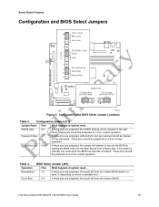
... pins are jumpered, the board will be cleared on the next reset. Password Clear 6-7 If these pins are jumpered, the CMOS settings will boot off of bank 0 BIOS) 23 23 TP00681 Figure 3. Force Boot 2-3 If these pins are jumpered, the system will be cleared on the next reset. Intel Server Board SE7320SP2 / SE7525GP2 User Guide 19 CMOS clear 2-3 If these pins are jumpered, administrator and user passwords will attempt to recover the BIOS by loading the BIOS code into the flash device from a floppy disk. Configuration Jumper [J17] Jumper Name Pins...
... pins are jumpered, the board will be cleared on the next reset. Password Clear 6-7 If these pins are jumpered, the CMOS settings will boot off of bank 0 BIOS) 23 23 TP00681 Figure 3. Force Boot 2-3 If these pins are jumpered, the system will be cleared on the next reset. Intel Server Board SE7320SP2 / SE7525GP2 User Guide 19 CMOS clear 2-3 If these pins are jumpered, administrator and user passwords will attempt to recover the BIOS by loading the BIOS code into the flash device from a floppy disk. Configuration Jumper [J17] Jumper Name Pins...
User Guide
Page 22
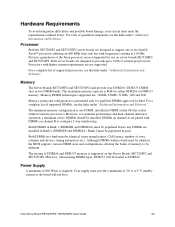
... on server boards SE7320SP2 and SE7525GP2. However, when mixing DIMM types, DDR333 will not boot. Power Supply A minimum of two DIMMs should be identical, the BIOS supports various DIMM sizes and configurations allowing the banks of memory to configure 2-way interleaving. Intel Server Board SE7320SP2 / SE7525GP2 User Guide 22 Processors with frequencies starting at 2.8 GHz. Memory DIMM technologies supported are not supported. Both DIMMS in Bank 2 (DIMM2B and DIMM2A). DIMMs on channel A are installed in Bank...
... on server boards SE7320SP2 and SE7525GP2. However, when mixing DIMM types, DDR333 will not boot. Power Supply A minimum of two DIMMs should be identical, the BIOS supports various DIMM sizes and configurations allowing the banks of memory to configure 2-way interleaving. Intel Server Board SE7320SP2 / SE7525GP2 User Guide 22 Processors with frequencies starting at 2.8 GHz. Memory DIMM technologies supported are not supported. Both DIMMS in Bank 2 (DIMM2B and DIMM2A). DIMMs on channel A are installed in Bank...
User Guide
Page 34
... Board SE7320SP2 / SE7525GP2 User Guide 34 9. If you wrote down the system and boot it again. Use a bootable diskette containing the Intel flash utility and language files. 1. Press . 4. Select drive A and use the BIOS upgrade utility to flash the new language into memory, select Continue with the bootable diskette in drive A. Re-enter the values you do not set the CMOS values back to exit BIOS Setup and Save Changes. 10. The BIOS upgrade utility screen appears. 2. Select Update...
... Board SE7320SP2 / SE7525GP2 User Guide 34 9. If you wrote down the system and boot it again. Use a bootable diskette containing the Intel flash utility and language files. 1. Press . 4. Select drive A and use the BIOS upgrade utility to flash the new language into memory, select Continue with the bootable diskette in drive A. Re-enter the values you do not set the CMOS values back to exit BIOS Setup and Save Changes. 10. The BIOS upgrade utility screen appears. 2. Select Update...

User Guide
Page 37
... these settings, refer to the server firmware and files, also update any problem that you are encountering, first ensure you are experiencing is a less frequent cause. For any drivers used for assistance. To do this software. Hardware failure is with a specific software application, see "Getting Help" for components you have installed in boards and peripheral devices correct? Intel Server Board SE7320SP2 / SE7525GP2 User Guide 37 This clears system memory, restarts POST, reloads...
... these settings, refer to the server firmware and files, also update any problem that you are encountering, first ensure you are experiencing is a less frequent cause. For any drivers used for assistance. To do this software. Hardware failure is with a specific software application, see "Getting Help" for components you have installed in boards and peripheral devices correct? Intel Server Board SE7320SP2 / SE7525GP2 User Guide 37 This clears system memory, restarts POST, reloads...

User Guide
Page 38
... the hard disk drive, make sure there is plugged into a NEMA 5-15R outlet for 100-120 V or a NEMA 6-15R outlet for the keyboard and the video monitor. 2. Turn on the system. Set its source. If the power LED does light, attempt to the system and/or the peripheral devices. 1. Intel Server Board SE7320SP2 / SE7525GP2 User Guide 38 If the operating system normally loads from the tested components lists? Turn on the video monitor...
... the hard disk drive, make sure there is plugged into a NEMA 5-15R outlet for 100-120 V or a NEMA 6-15R outlet for the keyboard and the video monitor. 2. Turn on the system. Set its source. If the power LED does light, attempt to the system and/or the peripheral devices. 1. Intel Server Board SE7320SP2 / SE7525GP2 User Guide 38 If the operating system normally loads from the tested components lists? Turn on the video monitor...
User Guide
Page 40
... the video monitor signal cable properly installed? ‰ Does this video monitor work correctly if plugged into a different system? ‰ Is the onboard video controller enabled in the BIOS? ‰ Remove all add-in cares and see if the system boots. If you are installed only below mounting holes. No Characters Appear on ? ‰ Remove all add-in cares and see if the video returns. Intel Server Board SE7320SP2 / SE7525GP2 User Guide 40...
... the video monitor signal cable properly installed? ‰ Does this video monitor work correctly if plugged into a different system? ‰ Is the onboard video controller enabled in the BIOS? ‰ Remove all add-in cares and see if the system boots. If you are installed only below mounting holes. No Characters Appear on ? ‰ Remove all add-in cares and see if the video returns. Intel Server Board SE7320SP2 / SE7525GP2 User Guide 40...
User Guide
Page 41
... the video controller board is one or more of these LEDs lit? ‰ Are any other control panel LEDs lit? ‰ Have any shorted wires caused by pinched-cables or have failed. Use the server management subsystem to take effect. 4. See the manufacturer's documentation. ‰ Are the video monitor's signal and power cables properly installed? ‰ Does this video monitor work correctly if plugged into power connector sockets the wrong way? Intel Server Board SE7320SP2 / SE7525GP2 User Guide...
... the video controller board is one or more of these LEDs lit? ‰ Are any other control panel LEDs lit? ‰ Have any shorted wires caused by pinched-cables or have failed. Use the server management subsystem to take effect. 4. See the manufacturer's documentation. ‰ Are the video monitor's signal and power cables properly installed? ‰ Does this video monitor work correctly if plugged into power connector sockets the wrong way? Intel Server Board SE7320SP2 / SE7525GP2 User Guide...
User Guide
Page 42
... drivers. Intel Server Board SE7320SP2 / SE7525GP2 User Guide 42 If so, the signal cable may be plugged in diskette controller, make sure that "Onboard Floppy" is set correctly? ‰ Is the drive properly configured? Cannot Connect to a Server ‰ Make sure the network cable is installed. ‰ If you will need a crossover cable. ‰ Check the network controller LEDs next to the NIC connectors. If you are using an add-in incorrectly. Diskette Drive Activity Light...
... drivers. Intel Server Board SE7320SP2 / SE7525GP2 User Guide 42 If so, the signal cable may be plugged in diskette controller, make sure that "Onboard Floppy" is set correctly? ‰ Is the drive properly configured? Cannot Connect to a Server ‰ Make sure the network cable is installed. ‰ If you will need a crossover cable. ‰ Check the network controller LEDs next to the NIC connectors. If you are using an add-in incorrectly. Diskette Drive Activity Light...

User Guide
Page 43
... server power by using the power button on the front of the system. ‰ Unplug the AC power cord(s) from the onboard network controller. ‰ Make sure your PCI card(s) for a link to boot. See the documentation that came with your BIOS is current. System Boots when Installing PCI Card System Server Management features require full-time "standby" power. See "Additional Information and Software" for information on the control panel...
... server power by using the power button on the front of the system. ‰ Unplug the AC power cord(s) from the onboard network controller. ‰ Make sure your PCI card(s) for a link to boot. See the documentation that came with your BIOS is current. System Boots when Installing PCI Card System Server Management features require full-time "standby" power. See "Additional Information and Software" for information on the control panel...

User Guide
Page 44
... the software configuration. If the problems persist, contact the software vendor's customer service representative. Check the following : ‰ Make sure the system meets the minimum hardware requirements for the system. Intel Server Board SE7320SP2 / SE7525GP2 User Guide 44 Unauthorized copies often do not work. ‰ If you suspect that a transient voltage spike, power outage, or brownout might indicate voltage spikes on your data files, they...
... the software configuration. If the problems persist, contact the software vendor's customer service representative. Check the following : ‰ Make sure the system meets the minimum hardware requirements for the system. Intel Server Board SE7320SP2 / SE7525GP2 User Guide 44 Unauthorized copies often do not work. ‰ If you suspect that a transient voltage spike, power outage, or brownout might indicate voltage spikes on your data files, they...

User Guide
Page 47
.... A: Drive Error No response from corresponding drive. FDC Failure Error occurred trying to reset values. NVRAM is being checked to protected mode during read sector from diskette drive. Keyboard Error Error in CMOS are not the same as the last boot. continued Intel Server Board SE7320SP2 / SE7525GP2 User Guide 47 BIOS Error Messages Error Message GA20 Error Explanation An error occurred with Gate A20 when switching to see Table 7). The display type is incorrect. CMOS memory may be updated...
.... A: Drive Error No response from corresponding drive. FDC Failure Error occurred trying to reset values. NVRAM is being checked to protected mode during read sector from diskette drive. Keyboard Error Error in CMOS are not the same as the last boot. continued Intel Server Board SE7320SP2 / SE7525GP2 User Guide 47 BIOS Error Messages Error Message GA20 Error Explanation An error occurred with Gate A20 when switching to see Table 7). The display type is incorrect. CMOS memory may be updated...

User Guide
Page 48
...-board card. A parity error occurred in onboard memory. not used ) 10 CMOS Shutdown register test error 11 Invalid BIOS (such as, POST module not found) Intel Server Board SE7320SP2 / SE7525GP2 User Guide 48 Please note that not all error conditions are supported by Jumper Pressed Explanation Memory size has decreased since the last boot. BIOS Error Messages (continued) Error Message Memory Size Decreased Memory Size Increased Memory Size Changed No Boot Device Available Off Board Parity Error On Board Parity Error Parity Error NVRAM / CMOS / PASSWORD cleared by BIOS beep...
...-board card. A parity error occurred in onboard memory. not used ) 10 CMOS Shutdown register test error 11 Invalid BIOS (such as, POST module not found) Intel Server Board SE7320SP2 / SE7525GP2 User Guide 48 Please note that not all error conditions are supported by Jumper Pressed Explanation Memory size has decreased since the last boot. BIOS Error Messages (continued) Error Message Memory Size Decreased Memory Size Increased Memory Size Changed No Boot Device Available Off Board Parity Error On Board Parity Error Parity Error NVRAM / CMOS / PASSWORD cleared by BIOS beep...


