
User Guide
Page 2
... need adequate airflow for a particular purpose, merchantability, or infringement of their specific application and environmental conditions. Intel server boards contain a number of high-density VLSI and power delivery components that chooses not to use of Intel products including liability or warranties relating to any of any other application in the United States and...
... need adequate airflow for a particular purpose, merchantability, or infringement of their specific application and environmental conditions. Intel server boards contain a number of high-density VLSI and power delivery components that chooses not to use of Intel products including liability or warranties relating to any of any other application in the United States and...
User Guide
Page 3
...shipped with the board or that may be used with the following Intel® Server Chassis: ƒ SC5200 BRP ƒ SC5250-E You may need or want to http://www.support.intel.com/support/motherboards/server/SE7210TP1-E. Use this chapter for step-bystep instructions and diagrams for a... link to help you will find a list of the server board features, photos of a problem. Information about which accessories, memory,...
...shipped with the board or that may be used with the following Intel® Server Chassis: ƒ SC5200 BRP ƒ SC5250-E You may need or want to http://www.support.intel.com/support/motherboards/server/SE7210TP1-E. Use this chapter for step-bystep instructions and diagrams for a... link to help you will find a list of the server board features, photos of a problem. Information about which accessories, memory,...
User Guide
Page 4
... you need more information about this product or information about the accessories that can be used with this server board, go to this link to find the information below: http://www.support.intel.com/support/motherboards/server/SE7210TP1-E/index.htm ƒ In-depth technical information about this product, including BIOS settings and chipset information in...
... you need more information about this product or information about the accessories that can be used with this server board, go to this link to find the information below: http://www.support.intel.com/support/motherboards/server/SE7210TP1-E/index.htm ƒ In-depth technical information about this product, including BIOS settings and chipset information in...

User Guide
Page 5
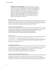
... System power on a grounded, static free surface. We recommend that the chassis, power supply, and other modules have passed EMC testing using this server board. Integration of your local Intel Representative. Hazardous conditions, devices and cables: Hazardous electrical conditions may require additional EMC compliance testing. Use a conductive foam pad if available but...
... System power on a grounded, static free surface. We recommend that the chassis, power supply, and other modules have passed EMC testing using this server board. Integration of your local Intel Representative. Hazardous conditions, devices and cables: Hazardous electrical conditions may require additional EMC compliance testing. Use a conductive foam pad if available but...
User Guide
Page 6
... performing any of fine needle nosed pliers. Resource CD http://www.support.intel.com/support/motherboards/server/SE7210TP1E. 上的 Intel Server Boards and Server Chassis Safety Information(《Intel Consignes de sécurité Lisez attention toutes les consignes de ...die Sicherheitshinweise zu IntelServerplatinen und -Servergehäusen auf der Ressourcen-CD oder unter http://www.support.intel.com/support/motherboards/server/SE7210TP1-E. Instrucciones de seguridad importantes Lea todas las declaraciones de seguridad y precaución de este documento antes...
... performing any of fine needle nosed pliers. Resource CD http://www.support.intel.com/support/motherboards/server/SE7210TP1E. 上的 Intel Server Boards and Server Chassis Safety Information(《Intel Consignes de sécurité Lisez attention toutes les consignes de ...die Sicherheitshinweise zu IntelServerplatinen und -Servergehäusen auf der Ressourcen-CD oder unter http://www.support.intel.com/support/motherboards/server/SE7210TP1-E. Instrucciones de seguridad importantes Lea todas las declaraciones de seguridad y precaución de este documento antes...
User Guide
Page 7
...Connector and Component Locations 13 Internal Component Connections 14 Configuration Jumpers ...15 Back Panel Connectors...16 Hardware Requirements ...17 2 Server Board Installations and Upgrades 19 Before You Begin ...19 Tools and Supplies Needed 19 Installing and Removing Memory 19 Installing ... or Replacing the Processor 21 Installing the Processor 21 Removing the Processor 24 Installing a PCI Card ...24 Replacing the Backup Battery 24 3 Server Utilities 27 BIOS Setup ...27 Upgrading the BIOS ...28 Preparing for the Upgrade 28 Upgrading the BIOS ...29 Changing the BIOS Language 30...
...Connector and Component Locations 13 Internal Component Connections 14 Configuration Jumpers ...15 Back Panel Connectors...16 Hardware Requirements ...17 2 Server Board Installations and Upgrades 19 Before You Begin ...19 Tools and Supplies Needed 19 Installing and Removing Memory 19 Installing ... or Replacing the Processor 21 Installing the Processor 21 Removing the Processor 24 Installing a PCI Card ...24 Replacing the Backup Battery 24 3 Server Utilities 27 BIOS Setup ...27 Upgrading the BIOS ...28 Preparing for the Upgrade 28 Upgrading the BIOS ...29 Changing the BIOS Language 30...
User Guide
Page 8
Contents CD-ROM Drive or DVD-ROM Drive Activity Light Does Not Light 36 Cannot Connect to a Server 37 Problems with Network 37 System Boots when Installing PCI Card 38 Problems with Newly Installed Application Software 38 Problems with Application Software that Ran ... (ICES-003 46 Europe (CE Declaration of Conformity 46 Taiwan Declaration of Conformity 46 Korean RRL Compliance 47 Australia / New Zealand 47 Getting Help ...48 Intel® Server Issue Report Form 49 viii
Contents CD-ROM Drive or DVD-ROM Drive Activity Light Does Not Light 36 Cannot Connect to a Server 37 Problems with Network 37 System Boots when Installing PCI Card 38 Problems with Newly Installed Application Software 38 Problems with Application Software that Ran ... (ICES-003 46 Europe (CE Declaration of Conformity 46 Taiwan Declaration of Conformity 46 Korean RRL Compliance 47 Australia / New Zealand 47 Getting Help ...48 Intel® Server Issue Report Form 49 viii
User Guide
Page 9
... the Processor Socket 22 Figure 10. Attaching the Fan Heat Sink Clips to the Processor 22 Figure 9. Table 8. Attaching the Heat Sink to the Processor Socket 23 Figure 11. Table 3. Installing the Processor in the Processor Socket 21 Figure 8. Table 7. Contents Figures Figure 1. Making Connections to the Server Board 14 Figure 4. Intel Server Board SE7210TP1-E Layout 13...
... the Processor Socket 22 Figure 10. Attaching the Fan Heat Sink Clips to the Processor 22 Figure 9. Table 8. Attaching the Heat Sink to the Processor Socket 23 Figure 11. Table 3. Installing the Processor in the Processor Socket 21 Figure 8. Table 7. Contents Figures Figure 1. Making Connections to the Server Board 14 Figure 4. Intel Server Board SE7210TP1-E Layout 13...

User Guide
Page 11
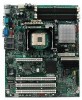
This chapter provides a photograph of the product, a list of the server board features, and diagrams showing the location of Intel® Server Board SE7210TP1-E. Figure 1. Intel® Server Board SE7210TP1-E Intel Server Board SE7210TP1-E User Guide 11 The Server Board SE7210TP1-E is provided for Serial ATA drives. ƒ The server board SE7210TP1SCSI includes a single channel, Ultra320 SCSI controller: Adaptec* AIC-7901. RAID 0 and 1 support...
This chapter provides a photograph of the product, a list of the server board features, and diagrams showing the location of Intel® Server Board SE7210TP1-E. Figure 1. Intel® Server Board SE7210TP1-E Intel Server Board SE7210TP1-E User Guide 11 The Server Board SE7210TP1-E is provided for Serial ATA drives. ƒ The server board SE7210TP1SCSI includes a single channel, Ultra320 SCSI controller: Adaptec* AIC-7901. RAID 0 and 1 support...
User Guide
Page 12
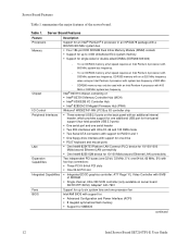
...; 8 megabit symmetrical flash memory ƒ Support for SMBIOS continued 12 Intel Server Board SE7210TP1-E User Guide Table 1. DDR333 memory will run DDR400 memory at full speed requires an Intel Pentium 4 processor with 533 MHz system bus frequency. Intel® 827210 chipset, consisting of 800 MHz. - To run DDR333 memory... at full speed requires an Intel Pentium 4 processor with a 800/533/400 MHz system bus ƒ Four 184-pin DDR SDRAM Dual Inline Memory Module (DIMM) sockets ƒ Support for up to 4 GB Unbuffered ECC system memory ƒ...
...; 8 megabit symmetrical flash memory ƒ Support for SMBIOS continued 12 Intel Server Board SE7210TP1-E User Guide Table 1. DDR333 memory will run DDR400 memory at full speed requires an Intel Pentium 4 processor with 533 MHz system bus frequency. Intel® 827210 chipset, consisting of 800 MHz. - To run DDR333 memory... at full speed requires an Intel Pentium 4 processor with a 800/533/400 MHz system bus ƒ Four 184-pin DDR SDRAM Dual Inline Memory Module (DIMM) sockets ƒ Support for up to 4 GB Unbuffered ECC system memory ƒ...
User Guide
Page 13
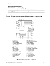
... Management Controller (mBMC) Server Board Connector and Component Locations BD AC E F ILIL HKHK GJJG FIIF EHEH DGDG CFFC EE DD CC BB AA Z Y A: Serial B Header B: CPU Fan Header C: Sys Fan Header 3 D: +12 V CPU Power Connector E: Sys Fan Header 4 F: Processor Socket G: DIMM 2B Socket H: DIMM 2A Socket I: DIMM 1B Socket J: DIMM 1A Socket K: Sys Fan Header...Slot 6, 32/33 GG: NIC 2 (10/100 Mbit) HH: NIC 1 (1 Gbit) II: Video Connector JJ: Serial A Connector KK: Keyboard and Mouse LL: USB Connectors Figure 2. Intel Server Board SE7210TP1-E Layout Intel Server Board SE7210TP1-E User Guide 13
... Management Controller (mBMC) Server Board Connector and Component Locations BD AC E F ILIL HKHK GJJG FIIF EHEH DGDG CFFC EE DD CC BB AA Z Y A: Serial B Header B: CPU Fan Header C: Sys Fan Header 3 D: +12 V CPU Power Connector E: Sys Fan Header 4 F: Processor Socket G: DIMM 2B Socket H: DIMM 2A Socket I: DIMM 1B Socket J: DIMM 1A Socket K: Sys Fan Header...Slot 6, 32/33 GG: NIC 2 (10/100 Mbit) HH: NIC 1 (1 Gbit) II: Video Connector JJ: Serial A Connector KK: Keyboard and Mouse LL: USB Connectors Figure 2. Intel Server Board SE7210TP1-E Layout Intel Server Board SE7210TP1-E User Guide 13
User Guide
Page 14
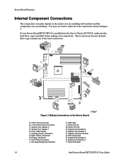
...Header 5 P: Chassis Intrusion Header Q: IDE Connectors R: System Fan Header 4 S: System Fan Header 3 T: Serial B Header 14 Intel Server Board SE7210TP1-E User Guide You may not need to the Server Board A: CPU1 Fan Connector B: +12V CPU Power Connector C: System Fan Header 2 D: System Fan Header 1 E: Front USB...Main Power Connector H: Floppy Connector I JU K TP00507 Figure 3. If your connections. This is installed before making your Server Board SE7210TP1-E is installed into and the components you are installing. Making Connections to make sure the hard drive cage is necessary ...
...Header 5 P: Chassis Intrusion Header Q: IDE Connectors R: System Fan Header 4 S: System Fan Header 3 T: Serial B Header 14 Intel Server Board SE7210TP1-E User Guide You may not need to the Server Board A: CPU1 Fan Connector B: +12V CPU Power Connector C: System Fan Header 2 D: System Fan Header 1 E: Front USB...Main Power Connector H: Floppy Connector I JU K TP00507 Figure 3. If your connections. This is installed before making your Server Board SE7210TP1-E is installed into and the components you are installing. Making Connections to make sure the hard drive cage is necessary ...
User Guide
Page 15
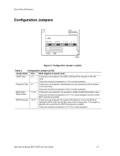
... normal operation. BIOS Recovery 14-15 If these pins are jumpered, it is typically only used when the BIOS has become corrupted. Intel Server Board SE7210TP1-E User Guide 15 Configuration Jumper Location Table 2. These pins should be cleared on 13-14 for normal BIOS operational updates.... Server Board Features Configuration Jumpers J1D1 15 14 13 11 10 9 765 3 21 TP00630 Figure 4. These pins should be jumpered on 10-...
... normal operation. BIOS Recovery 14-15 If these pins are jumpered, it is typically only used when the BIOS has become corrupted. Intel Server Board SE7210TP1-E User Guide 15 Configuration Jumper Location Table 2. These pins should be cleared on 13-14 for normal BIOS operational updates.... Server Board Features Configuration Jumpers J1D1 15 14 13 11 10 9 765 3 21 TP00630 Figure 4. These pins should be jumpered on 10-...

User Guide
Page 16
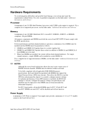
Server Board Features Back Panel Connectors AB C D EF TP00508 A. Table 3. Keyboard/mouse C. Back Panel Connectors The NIC LEDs at the right and left LED is on ) ... Blinking Amber Off Solid Amber Solid Green Description 10 Mbps connection (if right LED is on or blinking) 100 Mbps connection 1000 Mbps connection 16 Intel Server Board SE7210TP1-E User Guide Video E. Serial port A D. USB 1, 2, 3 B.
Server Board Features Back Panel Connectors AB C D EF TP00508 A. Table 3. Keyboard/mouse C. Back Panel Connectors The NIC LEDs at the right and left LED is on ) ... Blinking Amber Off Solid Amber Solid Green Description 10 Mbps connection (if right LED is on or blinking) 100 Mbps connection 1000 Mbps connection 16 Intel Server Board SE7210TP1-E User Guide Video E. Serial port A D. USB 1, 2, 3 B.
User Guide
Page 17
Server Board Features Hardware Requirements To avoid integration difficulties and possible board damage, your system must be populated as follows: ƒ DIMM1A and DIMM 1B: Populate these two sockets together first ƒ DIMM 2A and DIMM 2B: Populate these sockets in socket DIMM 1A. or ...non-SPD memory is required. To be fully compliant with DIMMs that support the Serial Presence Detect (SPD) data structure. Intel Server Board SE7210TP1-E User Guide 17 For ECC functionality, all applicable DDR SDRAM memory specifications, the board should be installed in addition to...
Server Board Features Hardware Requirements To avoid integration difficulties and possible board damage, your system must be populated as follows: ƒ DIMM1A and DIMM 1B: Populate these two sockets together first ƒ DIMM 2A and DIMM 2B: Populate these sockets in socket DIMM 1A. or ...non-SPD memory is required. To be fully compliant with DIMMs that support the Serial Presence Detect (SPD) data structure. Intel Server Board SE7210TP1-E User Guide 17 For ECC functionality, all applicable DDR SDRAM memory specifications, the board should be installed in addition to...
User Guide
Page 19
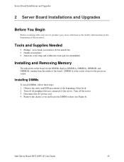
Observe the safety and ESD precautions at the beginning of this book. 2. Turn off the server. 3. Intel Server Board SE7210TP1-E User Guide 19 Disconnect the AC power cord. 4. Tools and Supplies Needed ƒ Phillips* (cross head) screwdriver (#1 bit and #2... cover and locate the DIMM sockets (see Figure 6). Turn off all peripheral devices connected to the server. DIMM1A is the socket closest to the processor socket. Server Board Installations and Upgrades 2 Server Board Installations and Upgrades Before You Begin Before working with your server product, pay close attention to...
Observe the safety and ESD precautions at the beginning of this book. 2. Turn off the server. 3. Intel Server Board SE7210TP1-E User Guide 19 Disconnect the AC power cord. 4. Tools and Supplies Needed ƒ Phillips* (cross head) screwdriver (#1 bit and #2... cover and locate the DIMM sockets (see Figure 6). Turn off all peripheral devices connected to the server. DIMM1A is the socket closest to the processor socket. Server Board Installations and Upgrades 2 Server Board Installations and Upgrades Before You Begin Before working with your server product, pay close attention to...
User Guide
Page 20
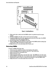
... cord from its anti-static package. 7. Remove the server's cover. 5. Position the DIMM above the socket. Turn off the server. 3. Reinstall and reconnect any parts you removed or disconnected to the open position. 6. Replace the server's cover and reconnect the AC power cord. 20 Intel Server Board SE7210TP1-E User Guide Observe the safety and ESD precautions at...
... cord from its anti-static package. 7. Remove the server's cover. 5. Position the DIMM above the socket. Turn off the server. 3. Reinstall and reconnect any parts you removed or disconnected to the open position. 6. Replace the server's cover and reconnect the AC power cord. 20 Intel Server Board SE7210TP1-E User Guide Observe the safety and ESD precautions at...
User Guide
Page 21
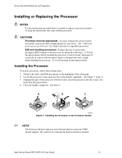
... Intel Server Board SE7210TP1-E User Guide 21 ESD and handling processors: Reduce the risk of this document. 2. Installing the Processor in the Processor Socket ✏ NOTE The bottom of the heat sink may damage the server board if you install a processor that came with the processor. Server ...(ESD) damage to install or replace a processor instead of your server. Close the handle completely. A B C TP00519 Figure 7. See letter B in contact with the socket, insert the processor into the socket. Keep part of using the instructions that is inappropriate for a ...
... Intel Server Board SE7210TP1-E User Guide 21 ESD and handling processors: Reduce the risk of this document. 2. Installing the Processor in the Processor Socket ✏ NOTE The bottom of the heat sink may damage the server board if you install a processor that came with the processor. Server ...(ESD) damage to install or replace a processor instead of your server. Close the handle completely. A B C TP00519 Figure 7. See letter B in contact with the socket, insert the processor into the socket. Keep part of using the instructions that is inappropriate for a ...
User Guide
Page 22
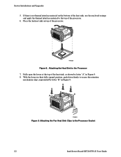
Server Installations and Upgrades 5. Place the fan heat sink on the bottom of the heat sink, use the enclosed syringe and apply the thermal interface material ... sink, as shown by letter "B" in Figure 9. TP00520 Figure 8. Attaching the Fan Heat Sink Clips to the Processor 7. Attaching the Heat Sink to the Processor Socket 22 Intel Server Board SE7210TP1-E User Guide With the levers in Figure 9. 8. B B B B A A C TP00521 Figure 9.
Server Installations and Upgrades 5. Place the fan heat sink on the bottom of the heat sink, use the enclosed syringe and apply the thermal interface material ... sink, as shown by letter "B" in Figure 9. TP00520 Figure 8. Attaching the Fan Heat Sink Clips to the Processor 7. Attaching the Heat Sink to the Processor Socket 22 Intel Server Board SE7210TP1-E User Guide With the levers in Figure 9. 8. B B B B A A C TP00521 Figure 9.
User Guide
Page 23
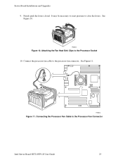
See Figure 10. Connect the processor fan cable to the Processor Fan Connector Intel Server Board SE7210TP1-E User Guide 23 See Figure 11. TP00522 Figure 10. Firmly push the levers closed. Connecting the Processor Fan Cable to the processor fan connector. It may be necessary to exert pressure to the Processor Socket 10. TP00523 Figure 11. Attaching the Fan Heat Sink Clips to close the levers. Server Board Installations and Upgrades 9.
See Figure 10. Connect the processor fan cable to the Processor Fan Connector Intel Server Board SE7210TP1-E User Guide 23 See Figure 11. TP00522 Figure 10. Firmly push the levers closed. Connecting the Processor Fan Cable to the processor fan connector. It may be necessary to exert pressure to the Processor Socket 10. TP00523 Figure 11. Attaching the Fan Heat Sink Clips to close the levers. Server Board Installations and Upgrades 9.


