User Guide
Page 7
... Component Locations 13 Internal Component Connections 14 Configuration Jumpers ...15 Back Panel Connectors...16 Hardware Requirements ...17 2 Server Board Installations and Upgrades 19 Before You Begin ...19 Tools and Supplies Needed 19 Installing and Removing Memory 19 Installing DIMMs...... or Replacing the Processor 21 Installing the Processor 21 Removing the Processor 24 Installing a PCI Card ...24 Replacing the Backup Battery 24 3 Server Utilities 27 BIOS Setup ...27 Upgrading the BIOS ...28 Preparing for the Upgrade 28 Upgrading the BIOS ...29 Changing the BIOS Language 30 ...
... Component Locations 13 Internal Component Connections 14 Configuration Jumpers ...15 Back Panel Connectors...16 Hardware Requirements ...17 2 Server Board Installations and Upgrades 19 Before You Begin ...19 Tools and Supplies Needed 19 Installing and Removing Memory 19 Installing DIMMs...... or Replacing the Processor 21 Installing the Processor 21 Removing the Processor 24 Installing a PCI Card ...24 Replacing the Backup Battery 24 3 Server Utilities 27 BIOS Setup ...27 Upgrading the BIOS ...28 Preparing for the Upgrade 28 Upgrading the BIOS ...29 Changing the BIOS Language 30 ...
User Guide
Page 9
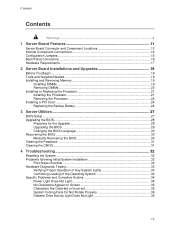
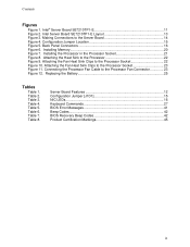
Back Panel Connectors 16 Figure 6. Installing the Processor in the Processor Socket 21 Figure 8. Table 5. Table 8. Contents Figures Figure 1. Replacing the Battery 25 Tables Table 1. Server Board Features 12 Configuration Jumper [J1D1 15 NIC LEDs...16 Keyboard Commands... 42 BIOS Recovery Beep Codes 42 Product Certification Markings 45 ix Intel Server Board SE7210TP1-E Layout 13 Figure 3. Attaching the Heat Sink to the Processor Socket 22 Figure 10. Intel® Server Board SE7210TP1-E 11 Figure 2. Installing Memory 20 Figure 7. Attaching the Fan...
Back Panel Connectors 16 Figure 6. Installing the Processor in the Processor Socket 21 Figure 8. Table 5. Table 8. Contents Figures Figure 1. Replacing the Battery 25 Tables Table 1. Server Board Features 12 Configuration Jumper [J1D1 15 NIC LEDs...16 Keyboard Commands... 42 BIOS Recovery Beep Codes 42 Product Certification Markings 45 ix Intel Server Board SE7210TP1-E Layout 13 Figure 3. Attaching the Heat Sink to the Processor Socket 22 Figure 10. Intel® Server Board SE7210TP1-E 11 Figure 2. Installing Memory 20 Figure 7. Attaching the Fan...
User Guide
Page 12
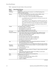
...be used with an Intel Pentium 4 processor with a 800/533/400 MHz system bus ƒ Four 184-pin DDR SDRAM Dual Inline Memory Module (DIMM) sockets ƒ Support for...server board SE7210TP1SCSI): Adaptec* AIC-7901 Support for SMBIOS continued 12 Intel Server Board SE7210TP1-E User Guide Intel® 827210 chipset, consisting of SDRAM ƒ Single channel, Ultra 320 SCSI controller (only available on the back panel... ATA connectors with support for RAID 0 and 1 ƒ One floppy drive interface with support for one drive ƒ PS/2* keyboard and mouse ports ƒ One Intel®...
...be used with an Intel Pentium 4 processor with a 800/533/400 MHz system bus ƒ Four 184-pin DDR SDRAM Dual Inline Memory Module (DIMM) sockets ƒ Support for...server board SE7210TP1SCSI): Adaptec* AIC-7901 Support for SMBIOS continued 12 Intel Server Board SE7210TP1-E User Guide Intel® 827210 chipset, consisting of SDRAM ƒ Single channel, Ultra 320 SCSI controller (only available on the back panel... ATA connectors with support for RAID 0 and 1 ƒ One floppy drive interface with support for one drive ƒ PS/2* keyboard and mouse ports ƒ One Intel®...
User Guide
Page 13
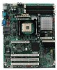
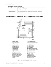
Intel Server Board SE7210TP1-E Layout Intel Server Board SE7210TP1-E User Guide 13 Server Board Features Server Board Features (continued) Power Management Support for ACPI: ƒ Suspend to RAM (STR) ƒ Wake on USB, PCI, RS-232, PS/2, LAN, and front panel Server Management Intel® Server Management 5.8 support via mini Baseboard Management Controller (mBMC) Server Board Connector and Component Locations BD AC E F ILIL HKHK GJJG...
Intel Server Board SE7210TP1-E Layout Intel Server Board SE7210TP1-E User Guide 13 Server Board Features Server Board Features (continued) Power Management Support for ACPI: ƒ Suspend to RAM (STR) ƒ Wake on USB, PCI, RS-232, PS/2, LAN, and front panel Server Management Intel® Server Management 5.8 support via mini Baseboard Management Controller (mBMC) Server Board Connector and Component Locations BD AC E F ILIL HKHK GJJG...
User Guide
Page 14
... F GN H I : Front Panel Connector J: Hot-swap Backplane Headers K: HDD LED L: SATA Port A1 M: SATA Port A2 N: System Fan Header 6 O: System Fan Header 5 P: Chassis Intrusion Header Q: IDE Connectors R: System Fan Header 4 S: System Fan Header 3 T: Serial B Header 14 Intel Server Board SE7210TP1-E User Guide You may not need to the Server Board A: CPU1 Fan Connector B: +12V CPU Power Connector C: System Fan...
... F GN H I : Front Panel Connector J: Hot-swap Backplane Headers K: HDD LED L: SATA Port A1 M: SATA Port A2 N: System Fan Header 6 O: System Fan Header 5 P: Chassis Intrusion Header Q: IDE Connectors R: System Fan Header 4 S: System Fan Header 3 T: Serial B Header 14 Intel Server Board SE7210TP1-E User Guide You may not need to the Server Board A: CPU1 Fan Connector B: +12V CPU Power Connector C: System Fan...

User Guide
Page 16
... connection (if left of each NIC provide the following information. Server Board Features Back Panel Connectors AB C D EF TP00508 A. NIC2 (10/100 Mbit) Figure 5. Video E. Back Panel Connectors The NIC LEDs at the right and left LED is on or blinking) 100 Mbps connection 1000 Mbps connection 16 Intel Server Board SE7210TP1-E User Guide USB 1, 2, 3 B. Keyboard/mouse C. Table...
... connection (if left of each NIC provide the following information. Server Board Features Back Panel Connectors AB C D EF TP00508 A. NIC2 (10/100 Mbit) Figure 5. Video E. Back Panel Connectors The NIC LEDs at the right and left LED is on or blinking) 100 Mbps connection 1000 Mbps connection 16 Intel Server Board SE7210TP1-E User Guide USB 1, 2, 3 B. Keyboard/mouse C. Table...
User Guide
Page 36
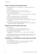
... it is an indication of these LEDs lit? ‰ Are any other front panel LEDs lit? ‰ Have any shorted wires caused by pinched-cables or have power connector plugs been forced into power connector sockets the wrong way? CD-ROM Drive or DVD-ROM Drive Activity Light Does Not ...configured? 36 Intel Server Board SE7210TP1-E User Guide If you are using an add-in response to a fan that has failed? ‰ Are the fan power connectors properly connected to the server board? ‰ Is the cable from the front panel board connected to the both the front panel board and to the server board? &#...
... it is an indication of these LEDs lit? ‰ Are any other front panel LEDs lit? ‰ Have any shorted wires caused by pinched-cables or have power connector plugs been forced into power connector sockets the wrong way? CD-ROM Drive or DVD-ROM Drive Activity Light Does Not ...configured? 36 Intel Server Board SE7210TP1-E User Guide If you are using an add-in response to a fan that has failed? ‰ Are the fan power connectors properly connected to the server board? ‰ Is the cable from the front panel board connected to the both the front panel board and to the server board? &#...
User Guide
Page 37
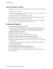
...adapter. Make sure your BIOS is securely attached to alter settings so that interrupts are using the correct and the current drivers. Intel Server Board SE7210TP1-E User Guide 37 For these drivers, it may be corrupt or deleted. See "Additional Information and Software" for the same ...require interrupts that came with other adapter supports shared interrupts. Problems with Network The server hangs when the drivers are loaded. ‰ Certain drivers may be necessary to the correct connector at the system back panel. ‰ Try a different network cable. ‰ Make sure you are ...
...adapter. Make sure your BIOS is securely attached to alter settings so that interrupts are using the correct and the current drivers. Intel Server Board SE7210TP1-E User Guide 37 For these drivers, it may be corrupt or deleted. See "Additional Information and Software" for the same ...require interrupts that came with other adapter supports shared interrupts. Problems with Network The server hangs when the drivers are loaded. ‰ Certain drivers may be necessary to the correct connector at the system back panel. ‰ Try a different network cable. ‰ Make sure you are ...


