

Product Specification
Page 5
Contents 1 Product Description 1.1 Overview 12 1.1.1 Feature Summary 12 1.1.2 Manufacturing Options 13 1.1.3 Board Layout 14 1.1.4 Block Diagram 16 1.2 Online Support 17 1.3 Processor 17 1.4 System Memory 18 1.4.1 Memory Configurations 20 1.5 Intel® 975X Chipset 24 1.5.1 USB 24 1.5.2 IDE Support 25 1.5.3 Real-Time Clock, CMOS ... Software 31 1.10.2 Audio Connectors 31 1.10.3 6-Channel (5.1) Audio Subsystem 32 1.11 LAN Subsystem 33 1.11.1 Intel® 82573E Gigabit Ethernet Controller 33 1.11.2 RJ-45 LAN Connector with Integrated LEDs 33 1.11.3 Alert Standard Format (ASF)...
Contents 1 Product Description 1.1 Overview 12 1.1.1 Feature Summary 12 1.1.2 Manufacturing Options 13 1.1.3 Board Layout 14 1.1.4 Block Diagram 16 1.2 Online Support 17 1.3 Processor 17 1.4 System Memory 18 1.4.1 Memory Configurations 20 1.5 Intel® 975X Chipset 24 1.5.1 USB 24 1.5.2 IDE Support 25 1.5.3 Real-Time Clock, CMOS ... Software 31 1.10.2 Audio Connectors 31 1.10.3 6-Channel (5.1) Audio Subsystem 32 1.11 LAN Subsystem 33 1.11.1 Intel® 82573E Gigabit Ethernet Controller 33 1.11.2 RJ-45 LAN Connector with Integrated LEDs 33 1.11.3 Alert Standard Format (ASF)...

Product Specification
Page 8
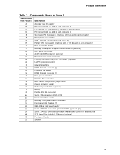
.... Wake-up Devices and Events 41 10. DMA Channels 49 12. Interrupts 52 15. Processor Fan and Auxiliary Rear Fan Header 58 21. Chassis Intrusion Header 59 22. Processor Core Power Connector (2 x 2 Pin 61 27. Auxiliary PCI Express Graphics Power 61 28... Zones 73 Tables 1. SCSI Hard Drive Activity LED Header (Optional 59 23. Processor Core Power Connector (2 x 4 Pin 61 26. States for Boards with the 6-Channel (5.1) Audio Subsystem 69 23. Intel Workstation Board S975XBX2 Technical Product Specification 22. Components Shown in Figure 20 57 17. System Memory ...
.... Wake-up Devices and Events 41 10. DMA Channels 49 12. Interrupts 52 15. Processor Fan and Auxiliary Rear Fan Header 58 21. Chassis Intrusion Header 59 22. Processor Core Power Connector (2 x 2 Pin 61 27. Auxiliary PCI Express Graphics Power 61 28... Zones 73 Tables 1. SCSI Hard Drive Activity LED Header (Optional 59 23. Processor Core Power Connector (2 x 4 Pin 61 26. States for Boards with the 6-Channel (5.1) Audio Subsystem 69 23. Intel Workstation Board S975XBX2 Technical Product Specification 22. Components Shown in Figure 20 57 17. System Memory ...
Product Specification
Page 11
1 Product Description What This Chapter Contains 1.1 Overview 12 1.2 Online Support 17 1.3 Processor 17 1.4 System Memory 18 1.5 Intel® 975X Chipset 24 1.6 Discrete Serial ATA Interface 27 1.7 PCI Express Connectors 28 1.8 IEEE-1394a Connectors 29 1.9 Legacy I/O Controller 29 1.10 Audio Subsystem 31 1.11 LAN Subsystem 33 1.12 Hardware Management Subsystem 36 1.13 Power Management 38 1.14 Trusted Platform Module 45 11
1 Product Description What This Chapter Contains 1.1 Overview 12 1.2 Online Support 17 1.3 Processor 17 1.4 System Memory 18 1.5 Intel® 975X Chipset 24 1.6 Discrete Serial ATA Interface 27 1.7 PCI Express Connectors 28 1.8 IEEE-1394a Connectors 29 1.9 Legacy I/O Controller 29 1.10 Audio Subsystem 31 1.11 LAN Subsystem 33 1.12 Hardware Management Subsystem 36 1.13 Power Management 38 1.14 Trusted Platform Module 45 11

Product Specification
Page 12
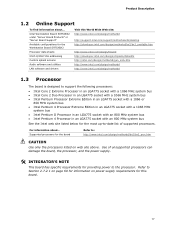
...• Intel® Pentium® 4 Processor Extreme Edition in an LGA775 socket with a 1066 MHz system bus • Intel® Pentium® D Processor in an LGA775 socket with an 800 MHz system bus • Intel® Pentium® 4 Processor in the... using the Intel® 82573E Gigabit Ethernet Controller continued 12 Intel Workstation Board S975XBX2 Technical Product Specification 1.1 Overview 1.1.1 Feature Summary Table 1 summarizes the major features of : • Intel® 82975X Memory Controller Hub (MCH) • Intel® 82801GR I/O Controller Hub (ICH7-R) Intel® High...
...• Intel® Pentium® 4 Processor Extreme Edition in an LGA775 socket with a 1066 MHz system bus • Intel® Pentium® D Processor in an LGA775 socket with an 800 MHz system bus • Intel® Pentium® 4 Processor in the... using the Intel® 82573E Gigabit Ethernet Controller continued 12 Intel Workstation Board S975XBX2 Technical Product Specification 1.1 Overview 1.1.1 Feature Summary Table 1 summarizes the major features of : • Intel® 82975X Memory Controller Hub (MCH) • Intel® 82801GR I/O Controller Hub (ICH7-R) Intel® High...
Product Specification
Page 13
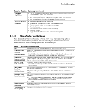
...and two IEEE-1394a connectors: one back panel connector and one front-panel header A 3-pin header for powering a fan for the Intel® 82975X Memory Controller Hub (MCH) Processor Core Power Connector One of range thermal values • Three fan headers • Three fan sense inputs used to use the same... • Thermal sense to detect out of the following connectors for Product Environmental Control Interface (PECI) 1.1.2 Manufacturing Options Table 2 describes the manufacturing options. Boards equipped with a dual-rail 2 x 4 power cable). Product Description Table 1.
...and two IEEE-1394a connectors: one back panel connector and one front-panel header A 3-pin header for powering a fan for the Intel® 82975X Memory Controller Hub (MCH) Processor Core Power Connector One of range thermal values • Three fan headers • Three fan sense inputs used to use the same... • Thermal sense to detect out of the following connectors for Product Environmental Control Interface (PECI) 1.1.2 Manufacturing Options Table 2 describes the manufacturing options. Boards equipped with a dual-rail 2 x 4 power cable). Product Description Table 1.
Product Specification
Page 15
...Conventional bus add-in card connector 1 Secondary PCI Express x16 (electrical x8) bus add-in card connector Front panel audio header Intel® 82801G I/O Controller Hub (ICH7-R) Primary PCI Express x16 (electrical x16 or x8) bus add-in card connector Rear ...Graphics Power Connector (optional) Back panel connectors ATAPI CD-ROM connector (optional) Processor core power connector Memory Controller Hub (MCH) fan header (optional) LGA775 processor socket Intel 82975X MCH DIMM Channel A sockets [2] Processor fan header DIMM Channel B sockets [2] Main power connector Diskette drive connector BIOS...
...Conventional bus add-in card connector 1 Secondary PCI Express x16 (electrical x8) bus add-in card connector Front panel audio header Intel® 82801G I/O Controller Hub (ICH7-R) Primary PCI Express x16 (electrical x16 or x8) bus add-in card connector Rear ...Graphics Power Connector (optional) Back panel connectors ATAPI CD-ROM connector (optional) Processor core power connector Memory Controller Hub (MCH) fan header (optional) LGA775 processor socket Intel 82975X MCH DIMM Channel A sockets [2] Processor fan header DIMM Channel B sockets [2] Main power connector Diskette drive connector BIOS...

Product Specification
Page 16
Intel Workstation Board S975XBX2 Technical Product Specification 1.1.4 Block Diagram Figure 2 is a block diagram of the major functional areas of the board. PCI Express x16 (Electrical x4) Slot Parallel ATA IDE Connector PCI Express Interface SMBus Parallel ATA IDE Interface Gigabit Ethernet Controller LAN Connector USB Back Panel/Front Panel USB Ports LGA775 Processor Socket System Bus (1066...
Intel Workstation Board S975XBX2 Technical Product Specification 1.1.4 Block Diagram Figure 2 is a block diagram of the major functional areas of the board. PCI Express x16 (Electrical x4) Slot Parallel ATA IDE Connector PCI Express Interface SMBus Parallel ATA IDE Interface Gigabit Ethernet Controller LAN Connector USB Back Panel/Front Panel USB Ports LGA775 Processor Socket System Bus (1066...
Product Specification
Page 17
... above. Refer to Section 2.7.2.1 on page 60 for information on power supply requirements for the board Refer to the processor. For information about ... Use of supported processors. Intel Workstation Board S975XBX2 under "Server Board Products" or "Server Board Support" Available configurations for the Workstation Board S975XBX2 Processor data sheets ICH7-R/ICH7-DH addressing Custom splash screens Audio software and utilities LAN software and...
... above. Refer to Section 2.7.2.1 on page 60 for information on power supply requirements for the board Refer to the processor. For information about ... Use of supported processors. Intel Workstation Board S975XBX2 under "Server Board Products" or "Server Board Support" Available configurations for the Workstation Board S975XBX2 Processor data sheets ICH7-R/ICH7-DH addressing Custom splash screens Audio software and utilities LAN software and...

Product Specification
Page 19
... , the memory frequency will operate at 533 MHz. Table 5. Table 5 lists the resulting operating memory frequencies based on available memory. Memory Operating Frequencies DIMM Type Processor System Bus Frequency DDR2 533 800 MHz DDR2 533 1066 MHz DDR2 667 800 MHz DDR2 667 1066 MHz DDR2 800 800 MHz DDR2 800... # INTEGRATOR'S NOTE Refer to Section 2.1.1, on page 47 for additional information on the combination of the DIMM type used with a 533 MHz system bus frequency processor, the memory will either be equal to or less than the...
... , the memory frequency will operate at 533 MHz. Table 5. Table 5 lists the resulting operating memory frequencies based on available memory. Memory Operating Frequencies DIMM Type Processor System Bus Frequency DDR2 533 800 MHz DDR2 533 1066 MHz DDR2 667 800 MHz DDR2 667 1066 MHz DDR2 800 800 MHz DDR2 800... # INTEGRATOR'S NOTE Refer to Section 2.1.1, on page 47 for additional information on the combination of the DIMM type used with a 533 MHz system bus frequency processor, the memory will either be equal to or less than the...
Product Specification
Page 25
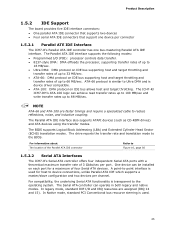
...A point-to-point interface is similar to 88 MB/sec. In legacy mode, standard IDE I /O (PIO): processor controls data transfer. • 8237-style DMA: DMA offloads the processor, supporting transfer rates of up to 16 MB/sec. • Ultra DMA: DMA protocol on IDE bus supporting .../sec per channel. In Native mode, standard PCI Conventional bus resource steering is transparent to the BIOS. Product Description 1.5.2 IDE Support The board provides five IDE interface connectors: • One parallel ATA IDE connector that supports two devices • Four serial ATA IDE connectors that...
...A point-to-point interface is similar to 88 MB/sec. In legacy mode, standard IDE I /O (PIO): processor controls data transfer. • 8237-style DMA: DMA offloads the processor, supporting transfer rates of up to 16 MB/sec. • Ultra DMA: DMA protocol on IDE bus supporting .../sec per channel. In Native mode, standard PCI Conventional bus resource steering is transparent to the BIOS. Product Description 1.5.2 IDE Support The board provides five IDE interface connectors: • One parallel ATA IDE connector that supports two devices • Four serial ATA IDE connectors that...
Product Specification
Page 34
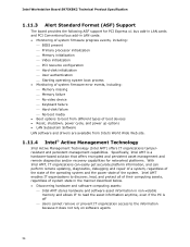
... access to the information because it does not rely on software agents 34 Intel Workstation Board S975XBX2 Technical Product Specification 1.11.3 Alert Standard Format (ASF) Support The board provides the following ASF support for PCI Express x1 bus add-in LAN cards...• Discovering hardware and software computing assets: ⎯ Intel AMT stores hardware and software asset information in LAN cards: • Monitoring of system firmware progress events, including: ⎯ BIOS present ⎯ Primary processor initialization ⎯ Memory initialization ⎯ Video initialization ⎯...
... access to the information because it does not rely on software agents 34 Intel Workstation Board S975XBX2 Technical Product Specification 1.11.3 Alert Standard Format (ASF) Support The board provides the following ASF support for PCI Express x1 bus add-in LAN cards...• Discovering hardware and software computing assets: ⎯ Intel AMT stores hardware and software asset information in LAN cards: • Monitoring of system firmware progress events, including: ⎯ BIOS present ⎯ Primary processor initialization ⎯ Memory initialization ⎯ Video initialization ⎯...
Product Specification
Page 36
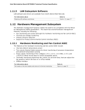
...Intel Workstation Board S975XBX2 Technical Product Specification 1.11.5 LAN Subsystem Software LAN software and drivers are available from Intel's World Wide Web site. For information about Obtaining LAN software and drivers Refer to Section 1.2, page 17 1.12 Hardware Management Subsystem The hardware management features enable the board...ASIC include: • Internal ambient temperature sensor • Two remote thermal diode sensors for direct monitoring of processor temperature and ambient temperature sensing • Power supply monitoring of five voltages (+5 V, +12 V, +3.3 VSB, +1.5 V,...
...Intel Workstation Board S975XBX2 Technical Product Specification 1.11.5 LAN Subsystem Software LAN software and drivers are available from Intel's World Wide Web site. For information about Obtaining LAN software and drivers Refer to Section 1.2, page 17 1.12 Hardware Management Subsystem The hardware management features enable the board...ASIC include: • Internal ambient temperature sensor • Two remote thermal diode sensors for direct monitoring of processor temperature and ambient temperature sensing • Power supply monitoring of five voltages (+5 V, +12 V, +3.3 VSB, +1.5 V,...

Product Specification
Page 37
Item Description A Thermal diode, located on processor die B Ambient temperature sensor, internal to hardware monitoring and fan control ASIC C Remote ambient temperature sensor D Processor fan header E Rear chassis fan header F Front chassis fan header G Auxiliary chassis fan header Figure 12. Product Description 1.12.2 Thermal Monitoring Figure 12 shows the location of the sensors and fan headers. Sensors and Fan Connectors 37
Item Description A Thermal diode, located on processor die B Ambient temperature sensor, internal to hardware monitoring and fan control ASIC C Remote ambient temperature sensor D Processor fan header E Rear chassis fan header F Front chassis fan header G Auxiliary chassis fan header Figure 12. Product Description 1.12.2 Thermal Monitoring Figure 12 shows the location of the sensors and fan headers. Sensors and Fan Connectors 37
Product Specification
Page 40
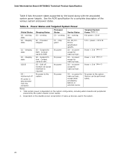
... D3 - Total system power is dependent on the standby power consumption of the various system and power states. working state S0 - Processor stopped C1 - S4 - device specification specific. Notes: 1. See the ACPI specification for wake-up logic. working state. sleeping state... system configuration, including add-in the system. 40 Table 8. No power to the system. No power to the system. Intel Workstation Board S975XBX2 Technical Product Specification Table 8 lists the power states supported by battery or external source. sleeping state G2/S5 S3 - Context...
... D3 - Total system power is dependent on the standby power consumption of the various system and power states. working state S0 - Processor stopped C1 - S4 - device specification specific. Notes: 1. See the ACPI specification for wake-up logic. working state. sleeping state... system configuration, including add-in the system. 40 Table 8. No power to the system. No power to the system. Intel Workstation Board S975XBX2 Technical Product Specification Table 8 lists the power states supported by battery or external source. sleeping state G2/S5 S3 - Context...
Product Specification
Page 57
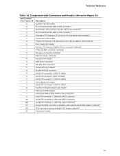
... x8) bus add-in card connector H Rear chassis fan header I Auxiliary PCI Express Graphics Power connector (optional) J ATAPI CD-ROM connector (optional) K Processor core power connector L MCH fan header (optional) M Processor fan header N Main power connector O Diskette drive connector P Chassis intrusion header Q Parallel ATA IDE connector R Serial ATA connector 3 (ICH7-R RAID) S Serial...
... x8) bus add-in card connector H Rear chassis fan header I Auxiliary PCI Express Graphics Power connector (optional) J ATAPI CD-ROM connector (optional) K Processor core power connector L MCH fan header (optional) M Processor fan header N Main power connector O Diskette drive connector P Chassis intrusion header Q Parallel ATA IDE connector R Serial ATA connector 3 (ICH7-R RAID) S Serial...

Product Specification
Page 58
... 2] Sense return (jack detection) # INTEGRATOR'S NOTE The front panel audio header is colored yellow. Intel Workstation Board S975XBX2 Technical Product Specification Table 17. Table 19. Front Chassis, Rear Chassis, and MCH Fan Headers Pin Signal Name 1 Control 2 +12 V 3 Tach Table 20. Processor Fan and Auxiliary Rear Fan Header Pin Signal Name 1 Ground 2 +12 V 3 FAN_TACH 4 FAN_CONTROL...
... 2] Sense return (jack detection) # INTEGRATOR'S NOTE The front panel audio header is colored yellow. Intel Workstation Board S975XBX2 Technical Product Specification Table 17. Table 19. Front Chassis, Rear Chassis, and MCH Fan Headers Pin Signal Name 1 Control 2 +12 V 3 Tach Table 20. Processor Fan and Auxiliary Rear Fan Header Pin Signal Name 1 Ground 2 +12 V 3 FAN_TACH 4 FAN_CONTROL...

Product Specification
Page 60
... (electrical x8) and the PCI Express x16 (electrical x4) bus add-in card connectors. Intel Workstation Board S975XBX2 Technical Product Specification 2.7.2.1 Power Supply Connectors The board has three power supply connectors: • Main power - The board requires a power supply with a dual-rail 2 x 4 Processor core power cable. If the board is equipped with a 2 x 4 power connector, you must be used .
... (electrical x8) and the PCI Express x16 (electrical x4) bus add-in card connectors. Intel Workstation Board S975XBX2 Technical Product Specification 2.7.2.1 Power Supply Connectors The board has three power supply connectors: • Main power - The board requires a power supply with a dual-rail 2 x 4 Processor core power cable. If the board is equipped with a 2 x 4 power connector, you must be used .

Product Specification
Page 61
... 20 No connect 21 +5 V 22 +5 V 23 +5 V 24 Ground Table 25. Rail 1 6 +12 V - Auxiliary PCI Express Graphics Power Pin Signal Name 1 +12 V 2 1 x 4 connector detect 3 Ground 4 +5 V 61 Processor Core Power Connector (2 x 2 Pin) Pin Signal Name 1 Ground 2 Ground Pin Signal Name 2 +12 V 4 +12 V Table 27. Technical Reference Table 24. Rail 1 7 +12 V - Rail 2 8 +12 V - Rail...
... 20 No connect 21 +5 V 22 +5 V 23 +5 V 24 Ground Table 25. Rail 1 6 +12 V - Auxiliary PCI Express Graphics Power Pin Signal Name 1 +12 V 2 1 x 4 connector detect 3 Ground 4 +5 V 61 Processor Core Power Connector (2 x 2 Pin) Pin Signal Name 1 Ground 2 Ground Pin Signal Name 2 +12 V 4 +12 V Table 27. Technical Reference Table 24. Rail 1 7 +12 V - Rail 2 8 +12 V - Rail...

Product Specification
Page 67
... modes: normal, configure, and recovery. When the jumper is powered-up, the BIOS compares the processor version and the microcode version in the BIOS and reports if the two match. A recovery diskette is displayed. Otherwise, the board could be damaged. Always turn off the power and unplug the power cord from the...
... modes: normal, configure, and recovery. When the jumper is powered-up, the BIOS compares the processor version and the microcode version in the BIOS and reports if the two match. A recovery diskette is displayed. Otherwise, the board could be damaged. Always turn off the power and unplug the power cord from the...

Product Specification
Page 70
... memory configurations but are based on the system's usage model and not necessarily tied to the processor, memory, and USB ports. Use the datasheets for the Workstation board is as PCI, to a heavy gaming environment with no applications running and no USB current draw...light load placed on a DC analysis of the board. The total +5 V current draw for add-in boards for add-in Board Considerations The board is designed to an environment with a 500 mA current draw per USB port. Intel Workstation Board S975XBX2 Technical Product Specification 2.10 Electrical Considerations 2.10.1 DC...
... memory configurations but are based on the system's usage model and not necessarily tied to the processor, memory, and USB ports. Use the datasheets for the Workstation board is as PCI, to a heavy gaming environment with no applications running and no USB current draw...light load placed on a DC analysis of the board. The total +5 V current draw for add-in boards for add-in Board Considerations The board is designed to an environment with a 500 mA current draw per USB port. Intel Workstation Board S975XBX2 Technical Product Specification 2.10 Electrical Considerations 2.10.1 DC...


