
Product Specification
Page 3
... need this level of the BIOS error messages, beep codes, and POST codes Regulatory compliance and battery disposal information Typographical Conventions This section contains information about the conventions used on the Workstation Board S975XBX2 A map of the resources of the Workstation Board The features supported by the BIOS Setup program A description of information. Preface This Technical Product Specification (TPS) specifies the board layout, components, connectors, power and environmental requirements, and the...
... need this level of the BIOS error messages, beep codes, and POST codes Regulatory compliance and battery disposal information Typographical Conventions This section contains information about the conventions used on the Workstation Board S975XBX2 A map of the resources of the Workstation Board The features supported by the BIOS Setup program A description of information. Preface This Technical Product Specification (TPS) specifies the board layout, components, connectors, power and environmental requirements, and the...

Product Specification
Page 5
... 1.1.2 Manufacturing Options 13 1.1.3 Board Layout 14 1.1.4 Block Diagram 16 1.2 Online Support 17 1.3 Processor 17 1.4 System Memory 18 1.4.1 Memory Configurations 20 1.5 Intel® 975X Chipset 24 1.5.1 USB 24 1.5.2 IDE Support 25 1.5.3 Real-Time Clock, CMOS SRAM, and Battery 26 1.6 Discrete Serial ATA Interface 27 1.6.1 Serial ATA Controller 27 1.6.2 External Serial ATA Support 27 1.7 PCI Express Connectors 28 1.8 IEEE-1394a Connectors 29 1.9 Legacy I/O Controller 29 1.9.1 Serial Port 29 1.9.2 Parallel Port 30 1.9.3 Diskette Drive Controller 30 1.9.4 Keyboard and Mouse...
... 1.1.2 Manufacturing Options 13 1.1.3 Board Layout 14 1.1.4 Block Diagram 16 1.2 Online Support 17 1.3 Processor 17 1.4 System Memory 18 1.4.1 Memory Configurations 20 1.5 Intel® 975X Chipset 24 1.5.1 USB 24 1.5.2 IDE Support 25 1.5.3 Real-Time Clock, CMOS SRAM, and Battery 26 1.6 Discrete Serial ATA Interface 27 1.6.1 Serial ATA Controller 27 1.6.2 External Serial ATA Support 27 1.7 PCI Express Connectors 28 1.8 IEEE-1394a Connectors 29 1.9 Legacy I/O Controller 29 1.9.1 Serial Port 29 1.9.2 Parallel Port 30 1.9.3 Diskette Drive Controller 30 1.9.4 Keyboard and Mouse...

Product Specification
Page 7
... DIMMs 22 7. Board Dimensions 68 vii Memory Channel and DIMM Configuration 20 4. Sensors and Fan Connectors 37 13. Dual Channel (Interleaved) Mode Configuration with Three DIMMs ......... 21 6. Component-side Connectors and Headers 56 17. Contents 3.7 Boot Options 81 3.7.1 CD-ROM Boot 81 3.7.2 Network Boot 81 3.7.3 Booting Without Attached Devices 82 3.7.4 Changing the Default Boot Device During POST 82 3.8 BIOS Security Features 83 4 Error Messages and Beep Codes 4.1 Speaker 85 4.2 BIOS Beep Codes 85 4.3 BIOS Error Messages 85 4.4 Port 80h POST Codes 86 5 Regulatory...
... DIMMs 22 7. Board Dimensions 68 vii Memory Channel and DIMM Configuration 20 4. Sensors and Fan Connectors 37 13. Dual Channel (Interleaved) Mode Configuration with Three DIMMs ......... 21 6. Component-side Connectors and Headers 56 17. Contents 3.7 Boot Options 81 3.7.1 CD-ROM Boot 81 3.7.2 Network Boot 81 3.7.3 Booting Without Attached Devices 82 3.7.4 Changing the Default Boot Device During POST 82 3.8 BIOS Security Features 83 4 Error Messages and Beep Codes 4.1 Speaker 85 4.2 BIOS Beep Codes 85 4.3 BIOS Error Messages 85 4.4 Port 80h POST Codes 86 5 Regulatory...

Product Specification
Page 8
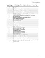
... Chassis Intrusion Header 59 22. Auxiliary PCI Express Graphics Power 61 28. States for Boards with the 6-Channel (5.1) Audio Subsystem 69 23. BIOS Setup Program Function Keys 78 39. Processor Core Power Connector (2 x 2 Pin 61 27. Environmental Specifications 75 37. Feature Summary 12 2. LAN Connector LED States 33 7. Intel Workstation Board S975XBX2 Technical Product Specification 22. Fan Header Current Capability 71 35. Boot Device Menu Options 82 40. Components Shown in Figure 20 57 17. I /O Map 50 13. Supervisor and User Password Functions...
... Chassis Intrusion Header 59 22. Auxiliary PCI Express Graphics Power 61 28. States for Boards with the 6-Channel (5.1) Audio Subsystem 69 23. BIOS Setup Program Function Keys 78 39. Processor Core Power Connector (2 x 2 Pin 61 27. Environmental Specifications 75 37. Feature Summary 12 2. LAN Connector LED States 33 7. Intel Workstation Board S975XBX2 Technical Product Specification 22. Fan Header Current Capability 71 35. Boot Device Menu Options 82 40. Components Shown in Figure 20 57 17. I /O Map 50 13. Supervisor and User Password Functions...

Product Specification
Page 12
... • PS/2* keyboard and mouse ports • Intel® BIOS resident in an LGA775 socket with an 800 MHz system bus • Intel® Pentium® 4 Processor in the SPI Flash device • Support for Advanced Configuration and Power Interface (ACPI), Plug and Play, and SMBIOS • Watchdog timer providing automatic recovery after two failed power-on self-tests (POSTs) • Support for PCI Local Bus Specification Revision 2.2 • Support for PCI Express* Revision 1.0a...
... • PS/2* keyboard and mouse ports • Intel® BIOS resident in an LGA775 socket with an 800 MHz system bus • Intel® Pentium® 4 Processor in the SPI Flash device • Support for Advanced Configuration and Power Interface (ACPI), Plug and Play, and SMBIOS • Watchdog timer providing automatic recovery after two failed power-on self-tests (POSTs) • Support for PCI Local Bus Specification Revision 2.2 • Support for PCI Express* Revision 1.0a...
Product Specification
Page 13
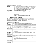
...x 4-pin (requires a power supply with the 2 x 4-pin processor core power connector will also include heatsinks in the processor voltage regulator area. • 2 x 2-pin SCSI Hard Drive LED Header Allows add-in all marketing channels. Boards equipped with a dual-rail 2 x 4 power cable). Feature Summary (continued) Expansion Capabilities Hardware Monitor Subsystem • Two PCI* Conventional bus add-in card connectors (SMBus routed to both the Secondary PCI Express x16 (electrical x8) and the PCI Express x16 (electrical x4) bus add-in card connectors Discrete SATA RAID Controller...
...x 4-pin (requires a power supply with the 2 x 4-pin processor core power connector will also include heatsinks in the processor voltage regulator area. • 2 x 2-pin SCSI Hard Drive LED Header Allows add-in all marketing channels. Boards equipped with a dual-rail 2 x 4 power cable). Feature Summary (continued) Expansion Capabilities Hardware Monitor Subsystem • Two PCI* Conventional bus add-in card connectors (SMBus routed to both the Secondary PCI Express x16 (electrical x8) and the PCI Express x16 (electrical x4) bus add-in card connectors Discrete SATA RAID Controller...

Product Specification
Page 16
...) LPC Bus I/O Controller Serial Port Parallel Port PS/2 Mouse PS/2 Keyboard Diskette Drive Connector Intel 82801GR/ 82801GH I/O Controller Hub (ICH7-R/ICH7-DH) Serial Peripheral Interface (SPI) Flash Device DMI Interconnect High Definition Audio Link LPC Bus Channel A DIMMs (2) Dual-Channel Memory Bus SMBus Channel B DIMMs (2) IEEE-1394a Connectors (Optional) IEEE-1394a Controller (Optional) PCI Bus SATA RAID Connectors (4) (Optional) PCI Slot 1 PCI Slot 2 Discrete SATA RAID Controller (Optional) PCI Bus PCI Bus SMBus Hardware Monitoring and Fan Control ASIC LPC Bus SATA IDE...
...) LPC Bus I/O Controller Serial Port Parallel Port PS/2 Mouse PS/2 Keyboard Diskette Drive Connector Intel 82801GR/ 82801GH I/O Controller Hub (ICH7-R/ICH7-DH) Serial Peripheral Interface (SPI) Flash Device DMI Interconnect High Definition Audio Link LPC Bus Channel A DIMMs (2) Dual-Channel Memory Bus SMBus Channel B DIMMs (2) IEEE-1394a Connectors (Optional) IEEE-1394a Controller (Optional) PCI Bus SATA RAID Connectors (4) (Optional) PCI Slot 1 PCI Slot 2 Discrete SATA RAID Controller (Optional) PCI Bus PCI Bus SMBus Hardware Monitoring and Fan Control ASIC LPC Bus SATA IDE...

Product Specification
Page 18
... non-ECC DIMMs • Serial Presence Detect • DDR2 800, DDR2 667, and DDR2 533 MHz SDRAM DIMMs NOTES • Remove the Primary PCI Express x16 (electrical x16 or x8) video card before installing or upgrading memory to Section 2.1.1 on page 47 for optimum performance. Intel Workstation Board S975XBX2 Technical Product Specification 1.4 System Memory The board has four DIMM sockets and supports the following memory features: • 1.8 V and 1.9 V DDR2...
... non-ECC DIMMs • Serial Presence Detect • DDR2 800, DDR2 667, and DDR2 533 MHz SDRAM DIMMs NOTES • Remove the Primary PCI Express x16 (electrical x16 or x8) video card before installing or upgrading memory to Section 2.1.1 on page 47 for optimum performance. Intel Workstation Board S975XBX2 Technical Product Specification 1.4 System Memory The board has four DIMM sockets and supports the following memory features: • 1.8 V and 1.9 V DDR2...

Product Specification
Page 24
... no device is stored in the Serial Peripheral Interface (SPI) Flash device. The ICH7 is a centralized controller for the board's I /O Controller Hub (ICH7-R) with dual stacked back panel connectors adjacent to the audio connectors • Four ports are implemented with DMI interconnect The MCH is a centralized controller for the system bus, the memory bus, the PCI Express bus, and the DMI interconnect. The ICH7-R provides the USB controller for full-speed devices. and EHCI-compatible drivers.
... no device is stored in the Serial Peripheral Interface (SPI) Flash device. The ICH7 is a centralized controller for the board's I /O Controller Hub (ICH7-R) with dual stacked back panel connectors adjacent to the audio connectors • Four ports are implemented with DMI interconnect The MCH is a centralized controller for the system bus, the memory bus, the PCI Express bus, and the DMI interconnect. The ICH7-R provides the USB controller for full-speed devices. and EHCI-compatible drivers.

Product Specification
Page 26
... the location of the add-in CMOS RAM (for configurations using the Microsoft Windows* XP and Microsoft Windows 2000 operating systems. NOTE Many Serial ATA drives use the same LED as the onboard IDE controller. Intel Workstation Board S975XBX2 Technical Product Specification Native mode is the preferred mode for example, the date and time) might not be accurate. When the voltage drops below a certain level, the BIOS Setup program settings stored in hard drive controller. data striping • RAID 1 -
... the location of the add-in CMOS RAM (for configurations using the Microsoft Windows* XP and Microsoft Windows 2000 operating systems. NOTE Many Serial ATA drives use the same LED as the onboard IDE controller. Intel Workstation Board S975XBX2 Technical Product Specification Native mode is the preferred mode for example, the date and time) might not be accurate. When the voltage drops below a certain level, the BIOS Setup program settings stored in hard drive controller. data striping • RAID 1 -
Product Specification
Page 34
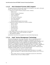
... and PCI Conventional bus add-in LAN cards: • Monitoring of system firmware progress events, including: ⎯ BIOS present ⎯ Primary processor initialization ⎯ Memory initialization ⎯ Video initialization ⎯ PCI resource configuration ⎯ Hard-disk initialization ⎯ User authentication ⎯ Starting operating system boot process • Monitoring of system firmware error events, including: ⎯ Memory missing ⎯ Memory failure ⎯ No video device ⎯ Keyboard failure ⎯ Hard-disk failure ⎯ No boot media • Boot options...
... and PCI Conventional bus add-in LAN cards: • Monitoring of system firmware progress events, including: ⎯ BIOS present ⎯ Primary processor initialization ⎯ Memory initialization ⎯ Video initialization ⎯ PCI resource configuration ⎯ Hard-disk initialization ⎯ User authentication ⎯ Starting operating system boot process • Monitoring of system firmware error events, including: ⎯ Memory missing ⎯ Memory failure ⎯ No video device ⎯ Keyboard failure ⎯ Hard-disk failure ⎯ No boot media • Boot options...

Product Specification
Page 47
... 2.4 PCI Configuration Space Map 51 2.5 Interrupts 52 2.6 PCI Conventional Interrupt Routing Map 53 2.7 Connectors 54 2.8 Jumper Block 67 2.9 Mechanical Considerations 68 2.10 Electrical Considerations 70 2.11 Thermal Considerations 72 2.12 Reliability 74 2.13 Environmental 75 2.1 Memory Resources 2.1.1 Addressable Memory The board utilizes 8 GB of 47 On a system that is allocated for PCI Conventional and PCI Express add-in cards, PCI Express configuration space, BIOS (SPI Flash device), and chipset overhead...
... 2.4 PCI Configuration Space Map 51 2.5 Interrupts 52 2.6 PCI Conventional Interrupt Routing Map 53 2.7 Connectors 54 2.8 Jumper Block 67 2.9 Mechanical Considerations 68 2.10 Electrical Considerations 70 2.11 Thermal Considerations 72 2.12 Reliability 74 2.13 Environmental 75 2.1 Memory Resources 2.1.1 Addressable Memory The board utilizes 8 GB of 47 On a system that is allocated for PCI Conventional and PCI Express add-in cards, PCI Express configuration space, BIOS (SPI Flash device), and chipset overhead...
Product Specification
Page 57
...Front panel audio header G Primary PCI Express x16 (electrical x16 or x8) bus add-in card connector H Rear chassis fan header I Auxiliary PCI Express Graphics Power connector (optional) J ATAPI CD-ROM connector (optional) K Processor core power connector L MCH fan header (optional) M Processor fan header N Main power connector O Diskette drive connector P Chassis intrusion header Q Parallel ATA IDE connector R Serial ATA connector 3 (ICH7-R RAID) S Serial ATA connector 2(ICH7-R RAID) T Serial ATA connector 1 (ICH7-R RAID) U Front chassis fan header V Serial ATA...
...Front panel audio header G Primary PCI Express x16 (electrical x16 or x8) bus add-in card connector H Rear chassis fan header I Auxiliary PCI Express Graphics Power connector (optional) J ATAPI CD-ROM connector (optional) K Processor core power connector L MCH fan header (optional) M Processor fan header N Main power connector O Diskette drive connector P Chassis intrusion header Q Parallel ATA IDE connector R Serial ATA connector 3 (ICH7-R RAID) S Serial ATA connector 2(ICH7-R RAID) T Serial ATA connector 1 (ICH7-R RAID) U Front chassis fan header V Serial ATA...
Product Specification
Page 77
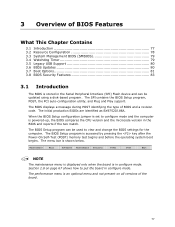
... Configuration 78 3.3 System Management BIOS (SMBIOS 79 3.4 Watchdog Timer 79 3.5 Legacy USB Support 80 3.6 BIOS Updates 80 3.7 Boot Options 81 3.8 BIOS Security Features 83 3.1 Introduction The BIOS is accessed by pressing the key after the Power-On Self-Test (POST) memory test begins and before the operating system boot begins. The BIOS displays a message during POST identifying the type of BIOS and a revision code. The SPI contains the BIOS Setup program, POST, the PCI auto-configuration utility, and Plug and Play support...
... Configuration 78 3.3 System Management BIOS (SMBIOS 79 3.4 Watchdog Timer 79 3.5 Legacy USB Support 80 3.6 BIOS Updates 80 3.7 Boot Options 81 3.8 BIOS Security Features 83 3.1 Introduction The BIOS is accessed by pressing the key after the Power-On Self-Test (POST) memory test begins and before the operating system boot begins. The BIOS displays a message during POST identifying the type of BIOS and a revision code. The SPI contains the BIOS Setup program, POST, the PCI auto-configuration utility, and Plug and Play support...
Product Specification
Page 78
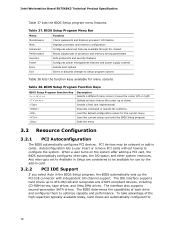
... the BIOS Setup program, the BIOS automatically sets up to ATA-66/100 and recognizes any ATAPI compliant devices, including CD-ROM drives, tape drives, and Ultra DMA drives. Table 37. Intel Workstation Board S975XBX2 Technical Product Specification Table 37 lists the BIOS Setup program menu features. When a user turns on the system after adding a PCI card, the BIOS automatically configures interrupts, the I /O channel support. BIOS Setup Program Menu Bar Menu Maintenance Main Function Clears passwords and displays processor information Displays processor and memory configuration...
... the BIOS Setup program, the BIOS automatically sets up to ATA-66/100 and recognizes any ATAPI compliant devices, including CD-ROM drives, tape drives, and Ultra DMA drives. Table 37. Intel Workstation Board S975XBX2 Technical Product Specification Table 37 lists the BIOS Setup program menu features. When a user turns on the system after adding a PCI card, the BIOS automatically configures interrupts, the I /O channel support. BIOS Setup Program Menu Bar Menu Maintenance Main Function Clears passwords and displays processor information Displays processor and memory configuration...
Product Specification
Page 79
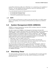
... managing computers in the BIOS Setup program. For example, do not connect an ATA hard drive as an ATAPI master device. Using SMBIOS, a system administrator can obtain the system types, capabilities, operational status, and installation dates for accessing this support, an SMBIOS service-level application running on a non-Plug and Play operating system can override the auto-configuration options by specifying manual configuration in a managed network. The MIF database...
... managing computers in the BIOS Setup program. For example, do not connect an ATA hard drive as an ATAPI master device. Using SMBIOS, a system administrator can obtain the system types, capabilities, operational status, and installation dates for accessing this support, an SMBIOS service-level application running on a non-Plug and Play operating system can override the auto-configuration options by specifying manual configuration in a managed network. The MIF database...
Product Specification
Page 81
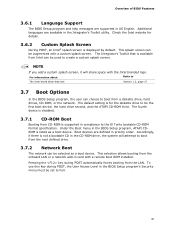
... Integrator's Toolkit that is supported in compliance to boot from the LAN. Boot devices are defined in card with a remote boot ROM installed. Pressing the key during POST, the User Access Level in the CD-ROM drive, the system will share space with a custom splash screen. The default setting is for details. 3.6.2 Custom Splash Screen During POST, an Intel® splash screen is displayed by default. Under the Boot menu in the BIOS Setup program, ATAPI CDROM is...
... Integrator's Toolkit that is supported in compliance to boot from the LAN. Boot devices are defined in card with a remote boot ROM installed. Pressing the key during POST, the User Access Level in the CD-ROM drive, the system will share space with a custom splash screen. The default setting is for details. 3.6.2 Custom Splash Screen During POST, an Intel® splash screen is displayed by default. Under the Boot menu in the BIOS Setup program, ATAPI CDROM is...
Product Specification
Page 83
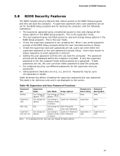
... displayed on the screen. Password to which password is entered. • Setting the user password restricts who can boot the computer. Users have access to Setup respective to Enter Setup None Password During Boot None Supervisor None User User Supervisor or Supervisor or user user 83 Table 40 shows the effects of options User only N/A Can change all Enter Password options Clear User Password Supervisor and user set Can change all options Can change Setup options in the BIOS Setup program. If only the supervisor password is set, pressing the key...
... displayed on the screen. Password to which password is entered. • Setting the user password restricts who can boot the computer. Users have access to Setup respective to Enter Setup None Password During Boot None Supervisor None User User Supervisor or Supervisor or user user 83 Table 40 shows the effects of options User only N/A Can change all Enter Password options Clear User Password Supervisor and user set Can change all options Can change Setup options in the BIOS Setup program. If only the supervisor password is set, pressing the key...
Product Specification
Page 86
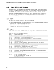
... CPU error. Reserved for determining the point where an error occurred. Table 43. Host Processors: 1F is an unrecoverable error. Reserved for future use (for future use (new input console codes) Boot devices: Includes fixed media and removable media. Intel Workstation Board S975XBX2 Technical Product Specification 4.4 Port 80h POST Codes During the POST, the BIOS generates diagnostic progress codes (POST-codes) to I /O buses: PCI, USB, ISA, ATA, etc. 5F is an unrecoverable error. Displaying the POST-codes requires a PCI bus add-in PCI bus connector...
... CPU error. Reserved for determining the point where an error occurred. Table 43. Host Processors: 1F is an unrecoverable error. Reserved for future use (for future use (new input console codes) Boot devices: Includes fixed media and removable media. Intel Workstation Board S975XBX2 Technical Product Specification 4.4 Port 80h POST Codes During the POST, the BIOS generates diagnostic progress codes (POST-codes) to I /O buses: PCI, USB, ISA, ATA, etc. 5F is an unrecoverable error. Displaying the POST-codes requires a PCI bus add-in PCI bus connector...
Product Specification
Page 87
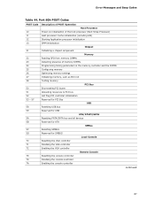
...memory settings Initializing memory, such as ECC init Testing memory PCI Bus Enumerating PCI buses Allocating resources to PCI bus Hot Plug PCI controller initialization Reserved for PCI Bus USB Resetting USB bus Reserved for USB ATA/ATAPI/SATA Resetting PATA/SATA bus and all devices Reserved for ATA SMBus Resetting SMBUS Reserved for SMBUS Local Console Resetting the VGA controller Disabling the VGA controller Enabling the VGA controller Remote Console Resetting the console controller Disabling the console controller Enabling the console controller continued 87 Error Messages and Beep Codes...
...memory settings Initializing memory, such as ECC init Testing memory PCI Bus Enumerating PCI buses Allocating resources to PCI bus Hot Plug PCI controller initialization Reserved for PCI Bus USB Resetting USB bus Reserved for USB ATA/ATAPI/SATA Resetting PATA/SATA bus and all devices Reserved for ATA SMBus Resetting SMBUS Reserved for SMBUS Local Console Resetting the VGA controller Disabling the VGA controller Enabling the VGA controller Remote Console Resetting the console controller Disabling the console controller Enabling the console controller continued 87 Error Messages and Beep Codes...


