

Product Specification
Page 2
... errata, which have an ordering number and are evaluated as medical, industrial, alarm systems, test equipment, etc. Changes to only the standard Intel® Workstation Board S975XBX2 with BIOS identifier BX97520J.86A. INTEL PRODUCTS ARE NOT INTENDED FOR USE IN MEDICAL, LIFE SAVING, OR LIFE SUSTAINING APPLICATIONS. Revision History Revision -001 Revision History First release of...
... errata, which have an ordering number and are evaluated as medical, industrial, alarm systems, test equipment, etc. Changes to only the standard Intel® Workstation Board S975XBX2 with BIOS identifier BX97520J.86A. INTEL PRODUCTS ARE NOT INTENDED FOR USE IN MEDICAL, LIFE SAVING, OR LIFE SUSTAINING APPLICATIONS. Revision History Revision -001 Revision History First release of...
Product Specification
Page 3
... information. Not all specifications of the BIOS error messages, beep codes, and POST codes Regulatory compliance and battery disposal information Typographical Conventions This section contains information about the Intel Workstation Board S975XBX2 and its components to the vendors, system... other engineers and technicians who need this specification. Intended Audience The TPS is specifically not intended for the Intel® Workstation Board S975XBX2. iii It is intended to provide detailed, technical information about the conventions used to call attention to important...
... information. Not all specifications of the BIOS error messages, beep codes, and POST codes Regulatory compliance and battery disposal information Typographical Conventions This section contains information about the Intel Workstation Board S975XBX2 and its components to the vendors, system... other engineers and technicians who need this specification. Intended Audience The TPS is specifically not intended for the Intel® Workstation Board S975XBX2. iii It is intended to provide detailed, technical information about the conventions used to call attention to important...

Product Specification
Page 6
Intel Workstation Board S975XBX2 Technical Product Specification 1.13 Power Management 38 1.13.1 ACPI 38 1.13.2 Hardware Support 41 1.14 Trusted Platform Module 45 2 Technical Reference 2.1 Memory Resources... 71 2.11 Thermal Considerations 72 2.12 Reliability 74 2.13 Environmental 75 3 Overview of BIOS Features 3.1 Introduction 77 3.2 Resource Configuration 78 3.2.1 PCI Autoconfiguration 78 3.2.2 PCI IDE Support 78 3.3 System Management BIOS (SMBIOS 79 3.4 Watchdog Timer 79 3.5 Legacy USB Support 80 3.6 BIOS Updates 80 3.6.1 Language Support 81 3.6.2 Custom Splash Screen 81 vi
Intel Workstation Board S975XBX2 Technical Product Specification 1.13 Power Management 38 1.13.1 ACPI 38 1.13.2 Hardware Support 41 1.14 Trusted Platform Module 45 2 Technical Reference 2.1 Memory Resources... 71 2.11 Thermal Considerations 72 2.12 Reliability 74 2.13 Environmental 75 3 Overview of BIOS Features 3.1 Introduction 77 3.2 Resource Configuration 78 3.2.1 PCI Autoconfiguration 78 3.2.2 PCI IDE Support 78 3.3 System Management BIOS (SMBIOS 79 3.4 Watchdog Timer 79 3.5 Legacy USB Support 80 3.6 BIOS Updates 80 3.6.1 Language Support 81 3.6.2 Custom Splash Screen 81 vi

Product Specification
Page 7
...Mode Configuration with One DIMM .......... 23 8. Location of the Jumper Block 67 21. Memory Channel and DIMM Configuration 20 4. Workstation Board Components 14 2. Dual Channel (Interleaved) Mode Configuration with Three DIMMs ......... 21 6. Dual Channel (Interleaved) Mode Configuration with...Booting Without Attached Devices 82 3.7.4 Changing the Default Boot Device During POST 82 3.8 BIOS Security Features 83 4 Error Messages and Beep Codes 4.1 Speaker 85 4.2 BIOS Beep Codes 85 4.3 BIOS Error Messages 85 4.4 Port 80h POST Codes 86 5 Regulatory Compliance and Battery ...
...Mode Configuration with One DIMM .......... 23 8. Location of the Jumper Block 67 21. Memory Channel and DIMM Configuration 20 4. Workstation Board Components 14 2. Dual Channel (Interleaved) Mode Configuration with Three DIMMs ......... 21 6. Dual Channel (Interleaved) Mode Configuration with...Booting Without Attached Devices 82 3.7.4 Changing the Default Boot Device During POST 82 3.8 BIOS Security Features 83 4 Error Messages and Beep Codes 4.1 Speaker 85 4.2 BIOS Beep Codes 85 4.3 BIOS Error Messages 85 4.4 Port 80h POST Codes 86 5 Regulatory Compliance and Battery ...

Product Specification
Page 8
...59 24. States for Components 74 36. Thermal Considerations for a Two-Color Power LED 64 32. Environmental Specifications 75 37. Intel Workstation Board S975XBX2 Technical Product Specification 22. I /O Shield Dimensions for a One-Color Power LED 64 31. Component-side Connectors and Headers Shown ...LED Header 62 29. Supported Memory Configurations 18 5. Chassis Intrusion Header 59 22. States for Boards with the 6-Channel (5.1) Audio Subsystem 69 23. BIOS Setup Program Function Keys 78 39. Components Shown in Figure 20 57 17. PCI Interrupt ...
...59 24. States for Components 74 36. Thermal Considerations for a Two-Color Power LED 64 32. Environmental Specifications 75 37. Intel Workstation Board S975XBX2 Technical Product Specification 22. I /O Shield Dimensions for a One-Color Power LED 64 31. Component-side Connectors and Headers Shown ...LED Header 62 29. Supported Memory Configurations 18 5. Chassis Intrusion Header 59 22. States for Boards with the 6-Channel (5.1) Audio Subsystem 69 23. BIOS Setup Program Function Keys 78 39. Components Shown in Figure 20 57 17. PCI Interrupt ...

Product Specification
Page 12
... of the board. Table 1. Intel Workstation Board S975XBX2 Technical Product Specification 1.1 Overview 1.1.1 Feature Summary Table 1 summarizes the major features of : • Intel® 82975X Memory Controller Hub (MCH) • Intel® 82801GR I/O Controller Hub (ICH7-R) Intel® High Definition Audio subsystem Legacy I/O Control Legacy I/O controller for diskette drive, serial, parallel, and PS/2 ports USB Peripheral Interfaces BIOS Instantly Available...
... of the board. Table 1. Intel Workstation Board S975XBX2 Technical Product Specification 1.1 Overview 1.1.1 Feature Summary Table 1 summarizes the major features of : • Intel® 82975X Memory Controller Hub (MCH) • Intel® 82801GR I/O Controller Hub (ICH7-R) Intel® High Definition Audio subsystem Legacy I/O Control Legacy I/O controller for diskette drive, serial, parallel, and PS/2 ports USB Peripheral Interfaces BIOS Instantly Available...
Product Specification
Page 13
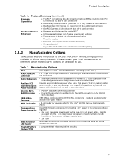
Product Description Table 1. Table 2. Boards equipped with the 2 x 4-pin processor core power connector will also include heatsinks in the processor voltage regulator area. • 2 x 2-pin SCSI Hard Drive... use the same LED as the onboard IDE controller Trusted Platform Module (TPM) A component that enhances platform security 13 Manufacturing Options AMT BIOS support for Intel® Active Management Technology (Intel® AMT) ATAPI CD-ROM Connector A 1 x 4-pin ATAPI-style connector for Product Environmental Control Interface (PECI) 1.1.2 Manufacturing Options Table 2 ...
Product Description Table 1. Table 2. Boards equipped with the 2 x 4-pin processor core power connector will also include heatsinks in the processor voltage regulator area. • 2 x 2-pin SCSI Hard Drive... use the same LED as the onboard IDE controller Trusted Platform Module (TPM) A component that enhances platform security 13 Manufacturing Options AMT BIOS support for Intel® Active Management Technology (Intel® AMT) ATAPI CD-ROM Connector A 1 x 4-pin ATAPI-style connector for Product Environmental Control Interface (PECI) 1.1.2 Manufacturing Options Table 2 ...
Product Specification
Page 15
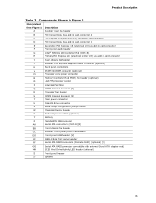
...Conventional bus add-in card connector 1 Secondary PCI Express x16 (electrical x8) bus add-in card connector Front panel audio header Intel® 82801G I/O Controller Hub (ICH7-R) Primary PCI Express x16 (electrical x16 or x8) bus add-in card connector Rear ...power connector Memory Controller Hub (MCH) fan header (optional) LGA775 processor socket Intel 82975X MCH DIMM Channel A sockets [2] Processor fan header DIMM Channel B sockets [2] Main power connector Diskette drive connector BIOS Setup configuration jumper block Chassis intrusion header Onboard power button (optional) Battery Parallel...
...Conventional bus add-in card connector 1 Secondary PCI Express x16 (electrical x8) bus add-in card connector Front panel audio header Intel® 82801G I/O Controller Hub (ICH7-R) Primary PCI Express x16 (electrical x16 or x8) bus add-in card connector Rear ...power connector Memory Controller Hub (MCH) fan header (optional) LGA775 processor socket Intel 82975X MCH DIMM Channel A sockets [2] Processor fan header DIMM Channel B sockets [2] Main power connector Diskette drive connector BIOS Setup configuration jumper block Chassis intrusion header Onboard power button (optional) Battery Parallel...

Product Specification
Page 18
...16/empty 64 M x 8/64 M x 8 128 M x 8/empty 128 M x 8/128 M x 8 Number of SDRAM devices on an ECC DIMM. 18 This allows the BIOS to read the SPD data and program the chipset to Section 2.1.1 on the total amount of SDRAM). 2. In the second column, "DS" refers to double...correctly configure the memory settings, but performance and reliability may not function under the determined frequency. Table 4. Intel Workstation Board S975XBX2 Technical Product Specification 1.4 System Memory The board has four DIMM sockets and supports the following memory features: • 1.8 V and 1.9 V DDR2 ...
...16/empty 64 M x 8/64 M x 8 128 M x 8/empty 128 M x 8/128 M x 8 Number of SDRAM devices on an ECC DIMM. 18 This allows the BIOS to read the SPD data and program the chipset to Section 2.1.1 on the total amount of SDRAM). 2. In the second column, "DS" refers to double...correctly configure the memory settings, but performance and reliability may not function under the determined frequency. Table 4. Intel Workstation Board S975XBX2 Technical Product Specification 1.4 System Memory The board has four DIMM sockets and supports the following memory features: • 1.8 V and 1.9 V DDR2 ...

Product Specification
Page 24
...Intel 82801GR I/O Controller Hub (ICH7-R) with dual stacked back panel connectors adjacent to the audio connectors • Four ports are routed to two separate front panel USB headers NOTES Computer systems that meets the requirements for all ports. The port arrangement is attached to the cable. The BIOS... are implemented with DMI interconnect The MCH is a centralized controller for the board's I/O paths. Intel Workstation Board S975XBX2 Technical Product Specification 1.5 Intel® 975X Chipset The Intel 975X chipset consists of the front panel USB headers Refer to eight USB ...
...Intel 82801GR I/O Controller Hub (ICH7-R) with dual stacked back panel connectors adjacent to the audio connectors • Four ports are routed to two separate front panel USB headers NOTES Computer systems that meets the requirements for all ports. The port arrangement is attached to the cable. The BIOS... are implemented with DMI interconnect The MCH is a centralized controller for the board's I/O paths. Intel Workstation Board S975XBX2 Technical Product Specification 1.5 Intel® 975X Chipset The Intel 975X chipset consists of the front panel USB headers Refer to eight USB ...
Product Specification
Page 25
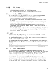
...ATA IDE interface supports the following modes: • Programmed I /O and IRQ resources are faster timings and require a specialized cable to the BIOS. For compatibility, the underlying Serial ATA functionality is used for a maximum of 3 Gbits/sec per connector 1.5.2.1 Parallel ATE IDE Interface The ... For information about The location of the Parallel ATA IDE connector Refer to the operating system. Product Description 1.5.2 IDE Support The board provides five IDE interface connectors: • One parallel ATA IDE connector that supports two devices • Four serial ATA IDE ...
...ATA IDE interface supports the following modes: • Programmed I /O and IRQ resources are faster timings and require a specialized cable to the BIOS. For compatibility, the underlying Serial ATA functionality is used for a maximum of 3 Gbits/sec per connector 1.5.2.1 Parallel ATE IDE Interface The ... For information about The location of the Parallel ATA IDE connector Refer to the operating system. Product Description 1.5.2 IDE Support The board provides five IDE interface connectors: • One parallel ATA IDE connector that supports two devices • Four serial ATA IDE ...

Product Specification
Page 26
... or power supplies equipped with an equivalent one. When the voltage drops below a certain level, the BIOS Setup program settings stored in hard drive controller. Figure 1 on the S975XBX2 board Refer to Figure 16, page 56 Table 22, page 59 1.5.3 Real-Time Clock, CMOS SRAM, ... time) might not be wired to ± 13 minutes/year at power-on. Replace the battery with low-voltage power connectors. Intel Workstation Board S975XBX2 Technical Product Specification Native mode is not plugged into CMOS RAM at 25 ºC with 3.3 VSB applied. distributed parity 1.5.2.4 SCSI Hard...
... or power supplies equipped with an equivalent one. When the voltage drops below a certain level, the BIOS Setup program settings stored in hard drive controller. Figure 1 on the S975XBX2 board Refer to Figure 16, page 56 Table 22, page 59 1.5.3 Real-Time Clock, CMOS SRAM, ... time) might not be wired to ± 13 minutes/year at power-on. Replace the battery with low-voltage power connectors. Intel Workstation Board S975XBX2 Technical Product Specification Native mode is not plugged into CMOS RAM at 25 ºC with 3.3 VSB applied. distributed parity 1.5.2.4 SCSI Hard...

Product Specification
Page 29
...• One parallel port with Extended Capabilities Port (ECP) and Enhanced Parallel Port (EPP) support • Serial IRQ interface compatible with BIOS support. 29 Bookmark not defined. Reference source not found., page Error! Figure 16, page 56 Section 2.7.2.6, page 66 1.9 Legacy I/O ...Controller The legacy I /O controller. 1.9.1 Serial Port The board has one serial port connector located on the component side. Product Description • SMBus 2.0 support • Wake# signal supporting wake events...
...• One parallel port with Extended Capabilities Port (ECP) and Enhanced Parallel Port (EPP) support • Serial IRQ interface compatible with BIOS support. 29 Bookmark not defined. Reference source not found., page Error! Figure 16, page 56 Section 2.7.2.6, page 66 1.9 Legacy I/O ...Controller The legacy I /O controller. 1.9.1 Serial Port The board has one serial port connector located on the component side. Product Description • SMBus 2.0 support • Wake# signal supporting wake events...
Product Specification
Page 30
... information about The location of the parallel port connector Refer to the computer should be turned off before a keyboard or mouse is connected or disconnected. Intel Workstation Board S975XBX2 Technical Product Specification For information about The location of the serial port A connector Refer to Figure 15, page 55 1.9.2 Parallel Port The 25-pin D-...is supported in the top PS/2 connector. Power to Figure 15, page 55 1.9.3 Diskette Drive Controller The legacy I/O controller supports one diskette drive. Use the BIOS Setup program to configure the diskette drive interface. Use the...
... information about The location of the parallel port connector Refer to the computer should be turned off before a keyboard or mouse is connected or disconnected. Intel Workstation Board S975XBX2 Technical Product Specification For information about The location of the serial port A connector Refer to Figure 15, page 55 1.9.2 Parallel Port The 25-pin D-...is supported in the top PS/2 connector. Power to Figure 15, page 55 1.9.3 Diskette Drive Controller The legacy I/O controller supports one diskette drive. Use the BIOS Setup program to configure the diskette drive interface. Use the...
Product Specification
Page 34
...because it does not rely on software agents 34 Intel Workstation Board S975XBX2 Technical Product Specification 1.11.3 Alert Standard Format (ASF) Support The board provides the following ASF support for networked platforms. With Intel AMT, IT organizations can easily get accurate platform ...Intel AMT is a hardware-based solution that offers encrypted and persistent asset management and remote diagnostics and/or recovery capabilities for PCI Express x1 bus add-in LAN cards and PCI Conventional bus add-in LAN cards: • Monitoring of system firmware progress events, including: ⎯ BIOS...
...because it does not rely on software agents 34 Intel Workstation Board S975XBX2 Technical Product Specification 1.11.3 Alert Standard Format (ASF) Support The board provides the following ASF support for networked platforms. With Intel AMT, IT organizations can easily get accurate platform ...Intel AMT is a hardware-based solution that offers encrypted and persistent asset management and remote diagnostics and/or recovery capabilities for PCI Express x1 bus add-in LAN cards and PCI Conventional bus add-in LAN cards: • Monitoring of system firmware progress events, including: ⎯ BIOS...

Product Specification
Page 35
Network drive or remote CD boot ⎯ Serial over LAN ⎯ OOB diagnostics ⎯ Remote control ⎯ Remote BIOS update • Proactive alerting that decreases downtime and minimizes time to repair: ⎯ Programmable policies ⎯ Operating system lock...help IT organizations detect and diagnose problems quickly to reduce end-user downtime • Protecting the enterprise against malicious software attacks: ⎯ Intel AMT helps IT organizations keep software versions and virus protection consistent and up alert ⎯ Boot failure alert ⎯ Hardware failure alerts ...
Network drive or remote CD boot ⎯ Serial over LAN ⎯ OOB diagnostics ⎯ Remote control ⎯ Remote BIOS update • Proactive alerting that decreases downtime and minimizes time to repair: ⎯ Programmable policies ⎯ Operating system lock...help IT organizations detect and diagnose problems quickly to reduce end-user downtime • Protecting the enterprise against malicious software attacks: ⎯ Intel AMT helps IT organizations keep software versions and virus protection consistent and up alert ⎯ Boot failure alert ⎯ Hardware failure alerts ...
Product Specification
Page 41
...# S1, S3, S4, S5 Note: For LAN and PME# signal, S5 is disabled by default in the S5 state. LAN ...from LAN in the BIOS Setup program. The board provides several power management hardware features, including: • Power connector • Fan headers • LAN wake capabilities • Instantly Available PC technology •...
...# S1, S3, S4, S5 Note: For LAN and PME# signal, S5 is disabled by default in the S5 state. LAN ...from LAN in the BIOS Setup program. The board provides several power management hardware features, including: • Power connector • Fan headers • LAN wake capabilities • Instantly Available PC technology •...

Product Specification
Page 42
... 42 When resuming from an ACPI state requires an operating system that can be set using the Last Power State feature in the BIOS Setup program's Boot menu. The method used depends on Ring and Wake from USB technologies from an AC power failure, the computer... support. 1.13.2.1 Power Connector When an ACPI-enabled system receives the appropriate command, the power supply removes all non-standby voltages. Intel Workstation Board S975XBX2 Technical Product Specification Resume on Ring enables telephony devices to access the computer when it was in before power was interrupted (on or ...
... 42 When resuming from an ACPI state requires an operating system that can be set using the Last Power State feature in the BIOS Setup program's Boot menu. The method used depends on Ring and Wake from USB technologies from an AC power failure, the computer... support. 1.13.2.1 Power Connector When an ACPI-enabled system receives the appropriate command, the power supply removes all non-standby voltages. Intel Workstation Board S975XBX2 Technical Product Specification Resume on Ring enables telephony devices to access the computer when it was in before power was interrupted (on or ...

Product Specification
Page 44
...computer wakes from an ACPI S1, S3, S4, or S5 state (with Wake on PME enabled in the BIOS). 1.13.2.9 WAKE# Signal Wake-up Support When the WAKE# signal on the S975XBX2 board. OM18534 Figure 13. Location of the standby power indicator LED on the PCI Express bus is asserted, the ... any devices connected to be off and the standby power indicator is still present even when the computer appears to the board. Intel Workstation Board S975XBX2 Technical Product Specification 1.13.2.6 Wake from USB USB bus activity wakes the computer from an ACPI S1, S3, S4, or S5 state. 1.13.2.10 +5 ...
...computer wakes from an ACPI S1, S3, S4, or S5 state (with Wake on PME enabled in the BIOS). 1.13.2.9 WAKE# Signal Wake-up Support When the WAKE# signal on the S975XBX2 board. OM18534 Figure 13. Location of the standby power indicator LED on the PCI Express bus is asserted, the ... any devices connected to be off and the standby power indicator is still present even when the computer appears to the board. Intel Workstation Board S975XBX2 Technical Product Specification 1.13.2.6 Wake from USB USB bus activity wakes the computer from an ACPI S1, S3, S4, or S5 state. 1.13.2.10 +5 ...

Product Specification
Page 47
...registers, internal graphics ranges, PCI Express ports (up to 512 MB) • Memory-mapped I/O that is allocated for PCI Conventional bus add-in cards The board provides the capability to reclaim the physical memory overlapped by the memory mapped I /O Map 50 2.4 PCI Configuration Space Map 51 2.5 Interrupts 52 2.6 PCI ... to the 4 GB boundary to system address space being allocated for PCI Conventional and PCI Express add-in cards, PCI Express configuration space, BIOS (SPI Flash device), and chipset overhead resides above the 4 GB boundary. On a system that has 8 GB of 47
...registers, internal graphics ranges, PCI Express ports (up to 512 MB) • Memory-mapped I/O that is allocated for PCI Conventional bus add-in cards The board provides the capability to reclaim the physical memory overlapped by the memory mapped I /O Map 50 2.4 PCI Configuration Space Map 51 2.5 Interrupts 52 2.6 PCI ... to the 4 GB boundary to system address space being allocated for PCI Conventional and PCI Express add-in cards, PCI Express configuration space, BIOS (SPI Flash device), and chipset overhead resides above the 4 GB boundary. On a system that has 8 GB of 47


