
Product Guide
Page 21
... transfer rate • Up to two SATA devices on the PCI bus segment in configuration cycles. Table 5. These are limited to a maximum of AD[31:16], which acts as a chip select on the server board S875WP1-E. This determines a unique PCI device ID value for RAID 0 (Striping), 1 (Mirroring), and ...sec. PCI Bus Configuration IDs IDSEL Value 16 Device PCI slot 1 (closest to AGP connector) 17 PCI slot 2 (middle slot) 18 PCI slot 3 (closest to left to right on the server board S875WP1LX, please see http://support.intel.com/support/motherboards/server/s875wp1e/sata-install.htm Server ...
... transfer rate • Up to two SATA devices on the PCI bus segment in configuration cycles. Table 5. These are limited to a maximum of AD[31:16], which acts as a chip select on the server board S875WP1-E. This determines a unique PCI device ID value for RAID 0 (Striping), 1 (Mirroring), and ...sec. PCI Bus Configuration IDs IDSEL Value 16 Device PCI slot 1 (closest to AGP connector) 17 PCI slot 2 (middle slot) 18 PCI slot 3 (closest to left to right on the server board S875WP1LX, please see http://support.intel.com/support/motherboards/server/s875wp1e/sata-install.htm Server ...

Product Guide
Page 54
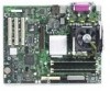
... the board (see http://support.intel.com/support/motherboards/server/s875wp1e/sata-install.htm 54 Intel Server Board S875WP1-E Product Guide Observe the precautions in "Before You Begin" on the server board S875WP1LX, please see Figure 19). 1. Connecting the SATA Cable TP00193 ✏ NOTE For instructions on installing and configuring Serial ATA RAID on the 4-port Promise...
... the board (see http://support.intel.com/support/motherboards/server/s875wp1e/sata-install.htm 54 Intel Server Board S875WP1-E Product Guide Observe the precautions in "Before You Begin" on the server board S875WP1LX, please see Figure 19). 1. Connecting the SATA Cable TP00193 ✏ NOTE For instructions on installing and configuring Serial ATA RAID on the 4-port Promise...
Product Guide
Page 75
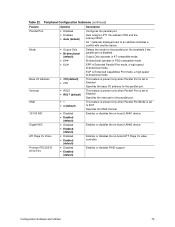
...; IRQ 7 (default) This feature is present only when Parallel Port is set to Enabled Specifies the base I/O address for the parallel port. Configuration Software and Utilities 75 An * (asterisk) displayed next to Enabled Specifies the interrupt for the parallel port. Base I/O Address • 378 (default...Parallel Port mode, a high-speed bi-directional mode. Promise PDC20319 S150 TX4 • Disabled • Enabled (default) Enables or disables RAID support. Table 22. Mode • Output Only • Bi-directional (default) Selects the mode for the parallel port. ECP is ...
...; IRQ 7 (default) This feature is present only when Parallel Port is set to Enabled Specifies the base I/O address for the parallel port. Configuration Software and Utilities 75 An * (asterisk) displayed next to Enabled Specifies the interrupt for the parallel port. Base I/O Address • 378 (default...Parallel Port mode, a high-speed bi-directional mode. Promise PDC20319 S150 TX4 • Disabled • Enabled (default) Enables or disables RAID support. Table 22. Mode • Output Only • Bi-directional (default) Selects the mode for the parallel port. ECP is ...
Product Guide
Page 77
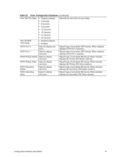
...Configuration Submenu (continued) Hard Disk Pre-Delay • Disabled (default) Specifies the hard disk drive pre-delay. • 3 Seconds • 6 Seconds • 9 Seconds • 12 Seconds • 15 Seconds • 21 Seconds • 30 Seconds Intel (R) RAID Technology • Disabled (default) • Enabled SATA... Port -0 Select to display sub-menu Reports type of connected SATA device. When selected, displays the Secondary IDE Master submenu....
...Configuration Submenu (continued) Hard Disk Pre-Delay • Disabled (default) Specifies the hard disk drive pre-delay. • 3 Seconds • 6 Seconds • 9 Seconds • 12 Seconds • 15 Seconds • 21 Seconds • 30 Seconds Intel (R) RAID Technology • Disabled (default) • Enabled SATA... Port -0 Select to display sub-menu Reports type of connected SATA device. When selected, displays the Secondary IDE Master submenu....


