
Product Guide
Page 1
Intel® Server System S7000FC4UR Product Guide A Guide for Technically Qualified Assemblers of Intel® Identified Subassemblies/Products Intel Order Number D93989-002
Intel® Server System S7000FC4UR Product Guide A Guide for Technically Qualified Assemblers of Intel® Identified Subassemblies/Products Intel Order Number D93989-002

Product Guide
Page 2
... the United States and other countries. * Other names and brands may be held responsible if components fail or the server board does not operate correctly when used together. All Rights Reserved ii Intel® Server System S7000FC4UR Product Guide Intel server boards contain a number of high-density VLSI and power delivery components that chooses not to use...
... the United States and other countries. * Other names and brands may be held responsible if components fail or the server board does not operate correctly when used together. All Rights Reserved ii Intel® Server System S7000FC4UR Product Guide Intel server boards contain a number of high-density VLSI and power delivery components that chooses not to use...

Product Guide
Page 3
...ühren. Consultez Intel Server Boards and Server Chassis Safety Information sur le Intel® Server Deployment Toolkit CD 2 ou bien rendezvous sur le site http://support.intel.com/support/motherboards/server/sb/cs-010770.htm. Vea Intel Server Boards and Server Chassis Safety Information en el Intel® Server Deployment Toolkit CD 2 y/o en http://support.intel.com/ support/motherboards/server/sb/cs-010770...
...ühren. Consultez Intel Server Boards and Server Chassis Safety Information sur le Intel® Server Deployment Toolkit CD 2 ou bien rendezvous sur le site http://support.intel.com/support/motherboards/server/sb/cs-010770.htm. Vea Intel Server Boards and Server Chassis Safety Information en el Intel® Server Deployment Toolkit CD 2 y/o en http://support.intel.com/ support/motherboards/server/sb/cs-010770...

Product Guide
Page 4
..., and other resource as a reference, pay close attention to chassis ground any components. They can result. iv Intel® Server System S7000FC4UR Product Guide Turn off the system AC power. Use a conductive foam pad if available but not the board wrapper. If one is not available,...personal injury or equipment damage can be present on /off: The power button DOES NOT turn off the server and disconnect the power cord, telecommunications systems, networks, and modems attached to ensure and maintain compliance with existing product certifications and approvals. To remove ...
..., and other resource as a reference, pay close attention to chassis ground any components. They can result. iv Intel® Server System S7000FC4UR Product Guide Turn off the system AC power. Use a conductive foam pad if available but not the board wrapper. If one is not available,...personal injury or equipment damage can be present on /off: The power button DOES NOT turn off the server and disconnect the power cord, telecommunications systems, networks, and modems attached to ensure and maintain compliance with existing product certifications and approvals. To remove ...

Product Guide
Page 5
... problems with a pair of the jumper with , but not squeeze, the pliers or other tool you may bend or break the pins on the board. Intel® Server System S7000FC4UR Product Guide v Installing or removing jumpers: A jumper is a small plastic encased conductor that jumper. Some jumpers have such a tab, take care when using needle...
... problems with a pair of the jumper with , but not squeeze, the pliers or other tool you may bend or break the pins on the board. Intel® Server System S7000FC4UR Product Guide v Installing or removing jumpers: A jumper is a small plastic encased conductor that jumper. Some jumpers have such a tab, take care when using needle...
Product Guide
Page 7
..., and instructions on how to add and replace components on the Intel® Server System S7000FC4UR Product Guide. At the back of this manual, see http://support.intel.com/support/motherboards/server/S7000FC4UR/. For the latest version of this book, you will find POST...; Chapter 2 describes how to start up and shut down the server. • Chapter 3 describes the Intel® Server System S7000FC4UR Deployment Toolkit CD. • Chapter 4 provides instructions for using the Intel® Server System S7000FC4UR. This includes how to navigate through the BIOS Setup screens, how...
..., and instructions on how to add and replace components on the Intel® Server System S7000FC4UR Product Guide. At the back of this manual, see http://support.intel.com/support/motherboards/server/S7000FC4UR/. For the latest version of this book, you will find POST...; Chapter 2 describes how to start up and shut down the server. • Chapter 3 describes the Intel® Server System S7000FC4UR Deployment Toolkit CD. • Chapter 4 provides instructions for using the Intel® Server System S7000FC4UR. This includes how to navigate through the BIOS Setup screens, how...

Product Guide
Page 8
... For drivers For firmware and BIOS updates For software to manage your Intel® server Use this Document or Software Intel® Server System S7000FC4UR Technical Product Specification Intel® Server System S7000FC4UR Quick Start User's Guide in the product box Spares and Configuration Guide Tested Hardware Operating Systems List Supported Processors Supported Memory Power Budget Platform Confidence Tests (PCT) Driver...
... For drivers For firmware and BIOS updates For software to manage your Intel® server Use this Document or Software Intel® Server System S7000FC4UR Technical Product Specification Intel® Server System S7000FC4UR Quick Start User's Guide in the product box Spares and Configuration Guide Tested Hardware Operating Systems List Supported Processors Supported Memory Power Budget Platform Confidence Tests (PCT) Driver...

Product Guide
Page 9
...Manual Organization vii Additional Information and Software viii Chapter 1: System Description 1 System Features 2 System Front 4 Front Control Panel 5 System Rear 10 Processors 12 System Memory 12 Power Subsystem 14 Power Supply Modules 14 Power...System Board Set 22 Main Board 23 Memory Board 28 I/O Riser Board (optional 30 SAS Riser Board (optional 31 Front Panel Board 32 SAS Backplane Board 33 Power Distribution Board 35 Server and Platform Management 35 Chapter 2: Starting Up and Shutting Down the Server 37 Powering Up the Server 37 Intel® Server System S7000FC4UR...
...Manual Organization vii Additional Information and Software viii Chapter 1: System Description 1 System Features 2 System Front 4 Front Control Panel 5 System Rear 10 Processors 12 System Memory 12 Power Subsystem 14 Power Supply Modules 14 Power...System Board Set 22 Main Board 23 Memory Board 28 I/O Riser Board (optional 30 SAS Riser Board (optional 31 Front Panel Board 32 SAS Backplane Board 33 Power Distribution Board 35 Server and Platform Management 35 Chapter 2: Starting Up and Shutting Down the Server 37 Powering Up the Server 37 Intel® Server System S7000FC4UR...
Product Guide
Page 10
... Keystroke Mappings 47 Limitations 48 Interface to Server Management 48 Platform Confidence Test 49 Running the Platform Confidence Test 50 Intel® Deployment Assistant 51 System Setup and Configuration Utilities 51 Save and Restore System Configuration (SYSCFG 52 FWPIAUPD Firmware Load Utility... and Removing PCI Express* Add-in Cards 68 Removing a Hot-swap PCI Card, Operating System Interface 69 Removing a Hot-swap PCI Card, Hardware Interface 71 Installing a Hot-swap PCI Card 72 Removing a Non-hot-swap PCI Card 74 x Intel® Server System S7000FC4UR Product Guide
... Keystroke Mappings 47 Limitations 48 Interface to Server Management 48 Platform Confidence Test 49 Running the Platform Confidence Test 50 Intel® Deployment Assistant 51 System Setup and Configuration Utilities 51 Save and Restore System Configuration (SYSCFG 52 FWPIAUPD Firmware Load Utility... and Removing PCI Express* Add-in Cards 68 Removing a Hot-swap PCI Card, Operating System Interface 69 Removing a Hot-swap PCI Card, Hardware Interface 71 Installing a Hot-swap PCI Card 72 Removing a Non-hot-swap PCI Card 74 x Intel® Server System S7000FC4UR Product Guide

Product Guide
Page 11
...DIMMs 81 Removing DIMMs 84 Chapter 6: Technician Maintenance 85 Before You Begin 85 Tools and Supplies Needed 85 System References 85 Component Locations 86 Removing and Installing the Top Cover 90 Removing the Top Cover 90 Installing ...Intel® Xeon® Processor MP 110 Installing and Removing a Processor Thermal Blank 111 Removing a Processor Thermal Blank 111 Installing a Processor Thermal Blank 112 Installing and Removing a Processor 113 Installing a Processor 113 Removing a Processor 115 Removing and Installing the Center Brace 116 Intel® Server System S7000FC4UR...
...DIMMs 81 Removing DIMMs 84 Chapter 6: Technician Maintenance 85 Before You Begin 85 Tools and Supplies Needed 85 System References 85 Component Locations 86 Removing and Installing the Top Cover 90 Removing the Top Cover 90 Installing ...Intel® Xeon® Processor MP 110 Installing and Removing a Processor Thermal Blank 111 Removing a Processor Thermal Blank 111 Installing a Processor Thermal Blank 112 Installing and Removing a Processor 113 Installing a Processor 113 Removing a Processor 115 Removing and Installing the Center Brace 116 Intel® Server System S7000FC4UR...

Product Guide
Page 12
...Board 118 Removing the I/O Riser Board 118 Installing and Removing the Intel® Remote Management Module 2 (Intel® RMM2 119 Installing the Intel® RMM2 and NIC Module 119 Removing the Intel® RMM2 and NIC Module 121 Replacing the Main Board 122... Safety Information 167 English ...167 Server Safety Information 167 Safety Warnings and Cautions 167 Intended Application Uses 168 Site Selection 168 Equipment Handling Practices 169 Power and Electrical Warnings 169 System Access Warnings 170 Rack Mount Warnings 171 xii Intel® Server System S7000FC4UR Product Guide
...Board 118 Removing the I/O Riser Board 118 Installing and Removing the Intel® Remote Management Module 2 (Intel® RMM2 119 Installing the Intel® RMM2 and NIC Module 119 Removing the Intel® RMM2 and NIC Module 121 Replacing the Main Board 122... Safety Information 167 English ...167 Server Safety Information 167 Safety Warnings and Cautions 167 Intended Application Uses 168 Site Selection 168 Equipment Handling Practices 169 Power and Electrical Warnings 169 System Access Warnings 170 Rack Mount Warnings 171 xii Intel® Server System S7000FC4UR Product Guide

Product Guide
Page 14
... 207 Limited Warranty for Intel® Chassis Subassembly Products 207 Extent of Limited Warranty 208 Warranty Limitations and Exclusions 208 Limitations of Liability 208 How to Obtain Warranty Service 209 Telephone Support 209 Returning a Defective Product 209 Appendix G: Getting Help 211 World Wide Web 211 Telephone 211 xiv Intel® Server System S7000FC4UR Product Guide
... 207 Limited Warranty for Intel® Chassis Subassembly Products 207 Extent of Limited Warranty 208 Warranty Limitations and Exclusions 208 Limitations of Liability 208 How to Obtain Warranty Service 209 Telephone Support 209 Returning a Defective Product 209 Appendix G: Getting Help 211 World Wide Web 211 Telephone 211 xiv Intel® Server System S7000FC4UR Product Guide

Product Guide
Page 15
... a PCI Add-in Card 73 Figure 38. Minimum Memory Population 79 Figure 42. Memory Board A and B Population 80 Intel® Server System S7000FC4UR Product Guide xv Front Panel Controls and Indicators 6 Figure 4. Peripheral Area 20 Figure 11. SAS Backplane Connectors (Interior Side 34... a Hard Drive Carrier 63 Figure 29. Removing a Memory Board 77 Figure 40. Intel® Server System S7000FC4UR 1 Figure 2. Hard Drive Carrier 62 Figure 28. Installing Hard Drive into Server 65 Figure 32. Main Board Component Locations 24 Figure 15. I/O Riser Board Connectors ...
... a PCI Add-in Card 73 Figure 38. Minimum Memory Population 79 Figure 42. Memory Board A and B Population 80 Intel® Server System S7000FC4UR Product Guide xv Front Panel Controls and Indicators 6 Figure 4. Peripheral Area 20 Figure 11. SAS Backplane Connectors (Interior Side 34... a Hard Drive Carrier 63 Figure 29. Removing a Memory Board 77 Figure 40. Intel® Server System S7000FC4UR 1 Figure 2. Hard Drive Carrier 62 Figure 28. Installing Hard Drive into Server 65 Figure 32. Main Board Component Locations 24 Figure 15. I/O Riser Board Connectors ...

Product Guide
Page 16
... Figure 55. Removing the Lower Center Air Baffle 96 Figure 56. Disconnecting SAS and SES Cables from Server 108 Figure 67. Installing the Intel® RAID Activation Key and DIMM 102 Figure 62. Removing 5 ¼-inch Peripheral Device from SAS...Intel® RMM2 121 Figure 79. Removing the PCI Dividers 123 Figure 80. Removing the Main Board 124 Figure 81. Installing the PCI Slot Dividers 126 Figure 83. Removing the Power Distribution Board 130 Figure 85. Installing the Power Distribution Board 131 Figure 86. Removing the Battery 135 xvi Intel® Server System S7000FC4UR...
... Figure 55. Removing the Lower Center Air Baffle 96 Figure 56. Disconnecting SAS and SES Cables from Server 108 Figure 67. Installing the Intel® RAID Activation Key and DIMM 102 Figure 62. Removing 5 ¼-inch Peripheral Device from SAS...Intel® RMM2 121 Figure 79. Removing the PCI Dividers 123 Figure 80. Removing the Main Board 124 Figure 81. Installing the PCI Slot Dividers 126 Figure 83. Removing the Power Distribution Board 130 Figure 85. Installing the Power Distribution Board 131 Figure 86. Removing the Battery 135 xvi Intel® Server System S7000FC4UR...

Product Guide
Page 17
Hot-swap PCI Slot Power and Attention LED 19 Table 5. Console Redirection Escape Sequences 47 Table 7. EFI Shell Commands 54 Table 8. POST Progress Codes and Messages 138 Table 10. Port 80 POST Code LEDs 137 Table 9. Product Regulatory Compliance Markings 198 Intel® Server System S7000FC4UR Product Guide xvii Setup Menu Key Use 42 Table 6. POST Error Manager Messages and Handling 142 Table 11. Tables Table 1. Additional Information and Software viii Table 2. System Status LED States 9 Table 4. Beep Codes 153 Table 12. Chassis Features 2 Table 3.
Hot-swap PCI Slot Power and Attention LED 19 Table 5. Console Redirection Escape Sequences 47 Table 7. EFI Shell Commands 54 Table 8. POST Progress Codes and Messages 138 Table 10. Port 80 POST Code LEDs 137 Table 9. Product Regulatory Compliance Markings 198 Intel® Server System S7000FC4UR Product Guide xvii Setup Menu Key Use 42 Table 6. POST Error Manager Messages and Handling 142 Table 11. Tables Table 1. Additional Information and Software viii Table 2. System Status LED States 9 Table 4. Beep Codes 153 Table 12. Chassis Features 2 Table 3.

Product Guide
Page 19
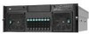
Intel® Server System S7000FC4UR AF002228 1 The system supports: • Hot-plug PCI Express* add-in cards • Hot-swap, redundant power supply modules • Hot-swap, redundant cooling fans • Memory with support for one to four Intel® Xeon® processors MP and 256 GB of DDR2 533 MHz / 667 MHz FBDIMM memory. 1 System Description The Intel® Server System S7000FC4UR is a compact, high-density, 4U rack-mount system with RAS features • Hot-swap hard drives Figure 1.
Intel® Server System S7000FC4UR AF002228 1 The system supports: • Hot-plug PCI Express* add-in cards • Hot-swap, redundant power supply modules • Hot-swap, redundant cooling fans • Memory with support for one to four Intel® Xeon® processors MP and 256 GB of DDR2 533 MHz / 667 MHz FBDIMM memory. 1 System Description The Intel® Server System S7000FC4UR is a compact, high-density, 4U rack-mount system with RAS features • Hot-swap hard drives Figure 1.

Product Guide
Page 20
...gigabit LAN ports with optional I/O riser board The optional Intel® Local Control Panel provides an LCD display that allows you to configure and monitor the health of the server independently from the operating system Front access to hot-swap hard drives Front access to...swap power supplies System power and system status LEDs System ID buttons and LEDs on front panel and rear of system Memory status LEDs Processor failure LEDs Color-coded parts to identify hot-swap and non-hot-swap serviceable components 2 Intel® Server System S7000FC4UR Product Guide System Features Feature ...
...gigabit LAN ports with optional I/O riser board The optional Intel® Local Control Panel provides an LCD display that allows you to configure and monitor the health of the server independently from the operating system Front access to hot-swap hard drives Front access to...swap power supplies System power and system status LEDs System ID buttons and LEDs on front panel and rear of system Memory status LEDs Processor failure LEDs Color-coded parts to identify hot-swap and non-hot-swap serviceable components 2 Intel® Server System S7000FC4UR Product Guide System Features Feature ...

Product Guide
Page 21
...optional I/O riser) System power button and LED System reset button NMI button System ID button and LED Optional Intel® Local Control Panel System status LED Hard drive status LED LAN1 and LAN2 status LEDs Video connector Three USB 2.0 ports Intel® Server System S7000FC4UR Product Guide 3 ...Chassis Features Description Two hot-plug PCI Express* slots. Up to eight hot-swap system fans in a redundant (1+1) configuration. four rear fans are required for...
...optional I/O riser) System power button and LED System reset button NMI button System ID button and LED Optional Intel® Local Control Panel System status LED Hard drive status LED LAN1 and LAN2 status LEDs Video connector Three USB 2.0 ports Intel® Server System S7000FC4UR Product Guide 3 ...Chassis Features Description Two hot-plug PCI Express* slots. Up to eight hot-swap system fans in a redundant (1+1) configuration. four rear fans are required for...

Product Guide
Page 22
Standard control panel shown. Front Components 4 Intel® Server System S7000FC4UR Product Guide Hot-swap fan modules (2) Hot-swap hard drives (8) Figure 2. System Front A B CD E F G F AF002229 Item A B C D E F G Description CD-ROM / DVD-ROM drive bay 5 ¼-inch peripheral bay Video connector USB 2.0 ports Front control panel.
Standard control panel shown. Front Components 4 Intel® Server System S7000FC4UR Product Guide Hot-swap fan modules (2) Hot-swap hard drives (8) Figure 2. System Front A B CD E F G F AF002229 Item A B C D E F G Description CD-ROM / DVD-ROM drive bay 5 ¼-inch peripheral bay Video connector USB 2.0 ports Front control panel.

Product Guide
Page 23
The standard control panel provides the following user interface for system management and status LEDs. Green blink SATA drives are installed and active Amber on Drive / slot failure Amber slow blink Predictive hard drive / slot failure ... LED Indicators C Hard drive activity Green / amber LED that indicates hard drive activity and faults LED LED State Drive State Green on empty slot (~2.5 Hz) Intel® Server System S7000FC4UR Product Guide 5 Front Control Panel You can choose between the standard control panel or the...
The standard control panel provides the following user interface for system management and status LEDs. Green blink SATA drives are installed and active Amber on Drive / slot failure Amber slow blink Predictive hard drive / slot failure ... LED Indicators C Hard drive activity Green / amber LED that indicates hard drive activity and faults LED LED State Drive State Green on empty slot (~2.5 Hz) Intel® Server System S7000FC4UR Product Guide 5 Front Control Panel You can choose between the standard control panel or the...

