
Product Guide
Page 1
Intel® Server System S7000FC4UR Product Guide A Guide for Technically Qualified Assemblers of Intel® Identified Subassemblies/Products Intel Order Number D93989-002
Intel® Server System S7000FC4UR Product Guide A Guide for Technically Qualified Assemblers of Intel® Identified Subassemblies/Products Intel Order Number D93989-002

Product Guide
Page 2
... components that chooses not to fitness for any other application in which the failure of Intel Corporation or its subsidiaries in the United States and other intellectual property right. All Rights Reserved ii Intel® Server System S7000FC4UR Product Guide Intel products are designed and tested to determine the amount of others. Disclaimer Information in this...
... components that chooses not to fitness for any other application in which the failure of Intel Corporation or its subsidiaries in the United States and other intellectual property right. All Rights Reserved ii Intel® Server System S7000FC4UR Product Guide Intel products are designed and tested to determine the amount of others. Disclaimer Information in this...

Product Guide
Page 3
... antes de realizar cualquiera de las instrucciones. See also Intel Server Boards and Server Chassis Safety Information on the Intel® Server Deployment Toolkit CD 2 and/or at http://support.intel.com/support/ motherboards/server/sb/cs-010770.htm. Consultez Intel Server Boards and Server Chassis Safety Information sur le Intel® Server Deployment Toolkit CD 2 ou bien rendezvous sur le site...
... antes de realizar cualquiera de las instrucciones. See also Intel Server Boards and Server Chassis Safety Information on the Intel® Server Deployment Toolkit CD 2 and/or at http://support.intel.com/support/ motherboards/server/sb/cs-010770.htm. Consultez Intel Server Boards and Server Chassis Safety Information sur le Intel® Server Deployment Toolkit CD 2 ou bien rendezvous sur le site...

Product Guide
Page 4
...ESD and handling boards: Always handle boards carefully. Hold boards only by wearing an antistatic wrist strap attached to ESD. iv Intel® Server System S7000FC4UR Product Guide After removing a board from its protective wrapper or from the wall outlet. Use of the product and will void ...the UL listing and other parts. To remove power from system, you open the chassis, add, or remove any unpainted metal surface on ...
...ESD and handling boards: Always handle boards carefully. Hold boards only by wearing an antistatic wrist strap attached to ESD. iv Intel® Server System S7000FC4UR Product Guide After removing a board from its protective wrapper or from the wall outlet. Use of the product and will void ...the UL listing and other parts. To remove power from system, you open the chassis, add, or remove any unpainted metal surface on ...

Product Guide
Page 5
... the narrow sides of fine needle nosed pliers. Gripping the wide sides can grip with the function controlled by that slips over two jumper pins. Intel® Server System S7000FC4UR Product Guide v Installing or removing jumpers: A jumper is a small plastic encased conductor that jumper. Some jumpers have such a tab, take care when using needle...
... the narrow sides of fine needle nosed pliers. Gripping the wide sides can grip with the function controlled by that slips over two jumper pins. Intel® Server System S7000FC4UR Product Guide v Installing or removing jumpers: A jumper is a small plastic encased conductor that jumper. Some jumpers have such a tab, take care when using needle...
Product Guide
Page 7
...and firmware updates, and how to perform these tasks. • Chapter 6 provides instructions for using the Intel® Server System S7000FC4UR. At the back of the server board and chassis features, and product diagrams to help " information, and the warranty. Preface About this... you identify components and their locations. • Chapter 2 describes how to start up and shut down the server. • Chapter 3 describes the Intel® Server System S7000FC4UR Deployment Toolkit CD. • Chapter 4 provides instructions for adding and replacing processors, memory, boards, and other...
...and firmware updates, and how to perform these tasks. • Chapter 6 provides instructions for using the Intel® Server System S7000FC4UR. At the back of the server board and chassis features, and product diagrams to help " information, and the warranty. Preface About this... you identify components and their locations. • Chapter 2 describes how to start up and shut down the server. • Chapter 3 describes the Intel® Server System S7000FC4UR Deployment Toolkit CD. • Chapter 4 provides instructions for adding and replacing processors, memory, boards, and other...

Product Guide
Page 8
... this product Processors that have been tested with this product DIMMs that have been tested with this product To make sure your Intel® server Use this Document or Software Intel® Server System S7000FC4UR Technical Product Specification Intel® Server System S7000FC4UR Quick Start User's Guide in -depth technical information about the accessories that can be used with this...
... this product Processors that have been tested with this product DIMMs that have been tested with this product To make sure your Intel® server Use this Document or Software Intel® Server System S7000FC4UR Technical Product Specification Intel® Server System S7000FC4UR Quick Start User's Guide in -depth technical information about the accessories that can be used with this...

Product Guide
Page 9
...Manual Organization vii Additional Information and Software viii Chapter 1: System Description 1 System Features 2 System Front 4 Front Control Panel 5 System Rear 10 Processors 12 System Memory 12 Power Subsystem 14 Power Supply Modules 14 Power...System Board Set 22 Main Board 23 Memory Board 28 I/O Riser Board (optional 30 SAS Riser Board (optional 31 Front Panel Board 32 SAS Backplane Board 33 Power Distribution Board 35 Server and Platform Management 35 Chapter 2: Starting Up and Shutting Down the Server 37 Powering Up the Server 37 Intel® Server System S7000FC4UR...
...Manual Organization vii Additional Information and Software viii Chapter 1: System Description 1 System Features 2 System Front 4 Front Control Panel 5 System Rear 10 Processors 12 System Memory 12 Power Subsystem 14 Power Supply Modules 14 Power...System Board Set 22 Main Board 23 Memory Board 28 I/O Riser Board (optional 30 SAS Riser Board (optional 31 Front Panel Board 32 SAS Backplane Board 33 Power Distribution Board 35 Server and Platform Management 35 Chapter 2: Starting Up and Shutting Down the Server 37 Powering Up the Server 37 Intel® Server System S7000FC4UR...
Product Guide
Page 10
... Keystroke Mappings 47 Limitations 48 Interface to Server Management 48 Platform Confidence Test 49 Running the Platform Confidence Test 50 Intel® Deployment Assistant 51 System Setup and Configuration Utilities 51 Save and Restore System Configuration (SYSCFG 52 FWPIAUPD Firmware Load Utility... and Removing PCI Express* Add-in Cards 68 Removing a Hot-swap PCI Card, Operating System Interface 69 Removing a Hot-swap PCI Card, Hardware Interface 71 Installing a Hot-swap PCI Card 72 Removing a Non-hot-swap PCI Card 74 x Intel® Server System S7000FC4UR Product Guide
... Keystroke Mappings 47 Limitations 48 Interface to Server Management 48 Platform Confidence Test 49 Running the Platform Confidence Test 50 Intel® Deployment Assistant 51 System Setup and Configuration Utilities 51 Save and Restore System Configuration (SYSCFG 52 FWPIAUPD Firmware Load Utility... and Removing PCI Express* Add-in Cards 68 Removing a Hot-swap PCI Card, Operating System Interface 69 Removing a Hot-swap PCI Card, Hardware Interface 71 Installing a Hot-swap PCI Card 72 Removing a Non-hot-swap PCI Card 74 x Intel® Server System S7000FC4UR Product Guide

Product Guide
Page 11
...DIMMs 81 Removing DIMMs 84 Chapter 6: Technician Maintenance 85 Before You Begin 85 Tools and Supplies Needed 85 System References 85 Component Locations 86 Removing and Installing the Top Cover 90 Removing the Top Cover 90 Installing ...Intel® Xeon® Processor MP 110 Installing and Removing a Processor Thermal Blank 111 Removing a Processor Thermal Blank 111 Installing a Processor Thermal Blank 112 Installing and Removing a Processor 113 Installing a Processor 113 Removing a Processor 115 Removing and Installing the Center Brace 116 Intel® Server System S7000FC4UR...
...DIMMs 81 Removing DIMMs 84 Chapter 6: Technician Maintenance 85 Before You Begin 85 Tools and Supplies Needed 85 System References 85 Component Locations 86 Removing and Installing the Top Cover 90 Removing the Top Cover 90 Installing ...Intel® Xeon® Processor MP 110 Installing and Removing a Processor Thermal Blank 111 Removing a Processor Thermal Blank 111 Installing a Processor Thermal Blank 112 Installing and Removing a Processor 113 Installing a Processor 113 Removing a Processor 115 Removing and Installing the Center Brace 116 Intel® Server System S7000FC4UR...

Product Guide
Page 12
...Board 118 Removing the I/O Riser Board 118 Installing and Removing the Intel® Remote Management Module 2 (Intel® RMM2 119 Installing the Intel® RMM2 and NIC Module 119 Removing the Intel® RMM2 and NIC Module 121 Replacing the Main Board 122... Safety Information 167 English ...167 Server Safety Information 167 Safety Warnings and Cautions 167 Intended Application Uses 168 Site Selection 168 Equipment Handling Practices 169 Power and Electrical Warnings 169 System Access Warnings 170 Rack Mount Warnings 171 xii Intel® Server System S7000FC4UR Product Guide
...Board 118 Removing the I/O Riser Board 118 Installing and Removing the Intel® Remote Management Module 2 (Intel® RMM2 119 Installing the Intel® RMM2 and NIC Module 119 Removing the Intel® RMM2 and NIC Module 121 Replacing the Main Board 122... Safety Information 167 English ...167 Server Safety Information 167 Safety Warnings and Cautions 167 Intended Application Uses 168 Site Selection 168 Equipment Handling Practices 169 Power and Electrical Warnings 169 System Access Warnings 170 Rack Mount Warnings 171 xii Intel® Server System S7000FC4UR Product Guide

Product Guide
Page 14
... 207 Limited Warranty for Intel® Chassis Subassembly Products 207 Extent of Limited Warranty 208 Warranty Limitations and Exclusions 208 Limitations of Liability 208 How to Obtain Warranty Service 209 Telephone Support 209 Returning a Defective Product 209 Appendix G: Getting Help 211 World Wide Web 211 Telephone 211 xiv Intel® Server System S7000FC4UR Product Guide
... 207 Limited Warranty for Intel® Chassis Subassembly Products 207 Extent of Limited Warranty 208 Warranty Limitations and Exclusions 208 Limitations of Liability 208 How to Obtain Warranty Service 209 Telephone Support 209 Returning a Defective Product 209 Appendix G: Getting Help 211 World Wide Web 211 Telephone 211 xiv Intel® Server System S7000FC4UR Product Guide

Product Guide
Page 15
... 61 Figure 27. Removing a Hard Drive Carrier 63 Figure 29. Opening Memory Board Latches 76 Figure 39. Intel® Server System S7000FC4UR 1 Figure 2. Intel® Local Control Panel 8 Figure 5. Memory Boards 13 Figure 7. Hard Drive Carrier 21 Figure 12. DVD-...Figure 21. Removing the Chassis Cover 58 Figure 23. Installing a Power Supply 68 Figure 35. Memory Board A and B Population 80 Intel® Server System S7000FC4UR Product Guide xv Front Components 4 Figure 3. Power Supply Indicators 15 Figure 8. Memory Board LEDs and Connectors 29 Figure 17. Installing a...
... 61 Figure 27. Removing a Hard Drive Carrier 63 Figure 29. Opening Memory Board Latches 76 Figure 39. Intel® Server System S7000FC4UR 1 Figure 2. Intel® Local Control Panel 8 Figure 5. Memory Boards 13 Figure 7. Hard Drive Carrier 21 Figure 12. DVD-...Figure 21. Removing the Chassis Cover 58 Figure 23. Installing a Power Supply 68 Figure 35. Memory Board A and B Population 80 Intel® Server System S7000FC4UR Product Guide xv Front Components 4 Figure 3. Power Supply Indicators 15 Figure 8. Memory Board LEDs and Connectors 29 Figure 17. Installing a...

Product Guide
Page 16
... ¼ Peripheral Device into the System 107 Figure 66. Open Processor Socket Release Lever 115 Figure 74. SAS Backplane Connectors (Interior Side 88 Figure 48. Disconnecting SAS and SES Cables from Server 108 Figure 67. Installing the Intel® RAID Activation Key and DIMM ...75. Attaching the EMI Gasket 120 Figure 77. Installing the Intel® RMM2 121 Figure 79. Removing the Front Panel I /O Board 133 Figure 88. Removing the Battery 135 xvi Intel® Server System S7000FC4UR Product Guide Removing the Top Cover 91 Figure 51. Installing the...
... ¼ Peripheral Device into the System 107 Figure 66. Open Processor Socket Release Lever 115 Figure 74. SAS Backplane Connectors (Interior Side 88 Figure 48. Disconnecting SAS and SES Cables from Server 108 Figure 67. Installing the Intel® RAID Activation Key and DIMM ...75. Attaching the EMI Gasket 120 Figure 77. Installing the Intel® RMM2 121 Figure 79. Removing the Front Panel I /O Board 133 Figure 88. Removing the Battery 135 xvi Intel® Server System S7000FC4UR Product Guide Removing the Top Cover 91 Figure 51. Installing the...

Product Guide
Page 17
System Status LED States 9 Table 4. EFI Shell Commands 54 Table 8. Port 80 POST Code LEDs 137 Table 9. Beep Codes 153 Table 12. Tables Table 1. Console Redirection Escape Sequences 47 Table 7. POST Progress Codes and Messages 138 Table 10. Product Regulatory Compliance Markings 198 Intel® Server System S7000FC4UR Product Guide xvii Hot-swap PCI Slot Power and Attention LED 19 Table 5. Setup Menu Key Use 42 Table 6. Chassis Features 2 Table 3. POST Error Manager Messages and Handling 142 Table 11. Additional Information and Software viii Table 2.
System Status LED States 9 Table 4. EFI Shell Commands 54 Table 8. Port 80 POST Code LEDs 137 Table 9. Beep Codes 153 Table 12. Tables Table 1. Console Redirection Escape Sequences 47 Table 7. POST Progress Codes and Messages 138 Table 10. Product Regulatory Compliance Markings 198 Intel® Server System S7000FC4UR Product Guide xvii Hot-swap PCI Slot Power and Attention LED 19 Table 5. Setup Menu Key Use 42 Table 6. Chassis Features 2 Table 3. POST Error Manager Messages and Handling 142 Table 11. Additional Information and Software viii Table 2.

Product Guide
Page 19
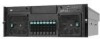
1 System Description The Intel® Server System S7000FC4UR is a compact, high-density, 4U rack-mount system with RAS features • Hot-swap hard drives Figure 1. Intel® Server System S7000FC4UR AF002228 1 The system supports: • Hot-plug PCI Express* add-in cards • Hot-swap, redundant power supply modules • Hot-swap, redundant cooling fans • Memory with support for one to four Intel® Xeon® processors MP and 256 GB of DDR2 533 MHz / 667 MHz FBDIMM memory.
1 System Description The Intel® Server System S7000FC4UR is a compact, high-density, 4U rack-mount system with RAS features • Hot-swap hard drives Figure 1. Intel® Server System S7000FC4UR AF002228 1 The system supports: • Hot-plug PCI Express* add-in cards • Hot-swap, redundant power supply modules • Hot-swap, redundant cooling fans • Memory with support for one to four Intel® Xeon® processors MP and 256 GB of DDR2 533 MHz / 667 MHz FBDIMM memory.

Product Guide
Page 20
...gigabit LAN ports with optional I/O riser board The optional Intel® Local Control Panel provides an LCD display that allows you to configure and monitor the health of the server independently from the operating system Front access to hot-swap hard drives Front access to...swap power supplies System power and system status LEDs System ID buttons and LEDs on front panel and rear of system Memory status LEDs Processor failure LEDs Color-coded parts to identify hot-swap and non-hot-swap serviceable components 2 Intel® Server System S7000FC4UR Product Guide System Features Feature ...
...gigabit LAN ports with optional I/O riser board The optional Intel® Local Control Panel provides an LCD display that allows you to configure and monitor the health of the server independently from the operating system Front access to hot-swap hard drives Front access to...swap power supplies System power and system status LEDs System ID buttons and LEDs on front panel and rear of system Memory status LEDs Processor failure LEDs Color-coded parts to identify hot-swap and non-hot-swap serviceable components 2 Intel® Server System S7000FC4UR Product Guide System Features Feature ...

Product Guide
Page 21
... features (requires optional I/O riser) System power button and LED System reset button NMI button System ID button and LED Optional Intel® Local Control Panel System status LED Hard drive status LED LAN1 and LAN2 status LEDs Video connector Three USB 2.0 ports Intel® Server System S7000FC4UR Product Guide 3 Chassis Features Description .... Eight hot-swap 2.5-inch SAS hard drives. Feature Availability Manageability Front control panel Table 2. Up to eight hot-swap system fans in a redundant (1+1) configuration. Dual power cords (1+1) when two power supplies are installed.
... features (requires optional I/O riser) System power button and LED System reset button NMI button System ID button and LED Optional Intel® Local Control Panel System status LED Hard drive status LED LAN1 and LAN2 status LEDs Video connector Three USB 2.0 ports Intel® Server System S7000FC4UR Product Guide 3 Chassis Features Description .... Eight hot-swap 2.5-inch SAS hard drives. Feature Availability Manageability Front control panel Table 2. Up to eight hot-swap system fans in a redundant (1+1) configuration. Dual power cords (1+1) when two power supplies are installed.

Product Guide
Page 22
System Front A B CD E F G F AF002229 Item A B C D E F G Description CD-ROM / DVD-ROM drive bay 5 ¼-inch peripheral bay Video connector USB 2.0 ports Front control panel. Front Components 4 Intel® Server System S7000FC4UR Product Guide Hot-swap fan modules (2) Hot-swap hard drives (8) Figure 2. Standard control panel shown.
System Front A B CD E F G F AF002229 Item A B C D E F G Description CD-ROM / DVD-ROM drive bay 5 ¼-inch peripheral bay Video connector USB 2.0 ports Front control panel. Front Components 4 Intel® Server System S7000FC4UR Product Guide Hot-swap fan modules (2) Hot-swap hard drives (8) Figure 2. Standard control panel shown.

Product Guide
Page 23
The standard control panel provides the following user interface for system management and status LEDs. Item Feature Description Front Panel Connectors A Video connector Standard VGA-compatible video port B Three USB connectors 2.0 port, 4-...faults LED LED State Drive State Green on empty slot (~2.5 Hz) Intel® Server System S7000FC4UR Product Guide 5 Front Control Panel You can choose between the standard control panel or the Intel® Local Control Panel to monitor and control your system locally. Green blink SATA drives are installed and active Amber on Drive...
The standard control panel provides the following user interface for system management and status LEDs. Item Feature Description Front Panel Connectors A Video connector Standard VGA-compatible video port B Three USB connectors 2.0 port, 4-...faults LED LED State Drive State Green on empty slot (~2.5 Hz) Intel® Server System S7000FC4UR Product Guide 5 Front Control Panel You can choose between the standard control panel or the Intel® Local Control Panel to monitor and control your system locally. Green blink SATA drives are installed and active Amber on Drive...