Product Specification
Page 2
... Chassis Intrusion header location change Jumper block location change ; Added Fan Domain Table in Section 4.3.2.2.1 - Added Appendix G Installation Guidelines - Updated Section 3.3.2 supported memory - Updated Appendix A: adding PCI device SEL event decoding tips - Added Section 3.13.3 Intel® Trusted Execution Technology(Intel® TXT) - Updated Block Diagram; Added Processor Stepping Mismatching on Table 2 - Updated Table 47 and Table 48, CPU 1 and CPU2 power connectors pin-out - Updated Table 87 BMC Beep Codes - Updated Figure 53 Power Distribution Block Diagram...
... Chassis Intrusion header location change Jumper block location change ; Added Fan Domain Table in Section 4.3.2.2.1 - Added Appendix G Installation Guidelines - Updated Section 3.3.2 supported memory - Updated Appendix A: adding PCI device SEL event decoding tips - Added Section 3.13.3 Intel® Trusted Execution Technology(Intel® TXT) - Updated Block Diagram; Added Processor Stepping Mismatching on Table 2 - Updated Table 47 and Table 48, CPU 1 and CPU2 power connectors pin-out - Updated Table 87 BMC Beep Codes - Updated Figure 53 Power Distribution Block Diagram...
Product Specification
Page 6
... Header ...111 6.4 Front Panel Connector 111 6.5 I/O Connectors ...112 6.5.1 VGA Connector ...112 6.5.2 NIC Connectors ...113 6.5.3 SATA Connectors 113 6.5.4 SAS Module Slot 113 6.5.5 Serial Port Connectors 114 6.5.6 USB Connector ...115 6.6 Fan Headers...116 7. Jumper Blocks...118 7.1 CMOS Clear and Password Reset Usage Procedure 119 7.1.1 Clearing the CMOS 119 7.1.2 Clearing the Password 119 7.2 Force BMC Update Procedure 120 7.3 BIOS Recovery Jumper 120 8. Table of Contents Intel® Server Boards S5520HC, S5500HCV, and S5520HCT TPS 5.3 BIOS Setup Utility...
... Header ...111 6.4 Front Panel Connector 111 6.5 I/O Connectors ...112 6.5.1 VGA Connector ...112 6.5.2 NIC Connectors ...113 6.5.3 SATA Connectors 113 6.5.4 SAS Module Slot 113 6.5.5 Serial Port Connectors 114 6.5.6 USB Connector ...115 6.6 Fan Headers...116 7. Jumper Blocks...118 7.1 CMOS Clear and Password Reset Usage Procedure 119 7.1.1 Clearing the CMOS 119 7.1.2 Clearing the Password 119 7.2 Force BMC Update Procedure 120 7.3 BIOS Recovery Jumper 120 8. Table of Contents Intel® Server Boards S5520HC, S5500HCV, and S5520HCT TPS 5.3 BIOS Setup Utility...
Product Specification
Page 11
.... VGA Connector Pin-out (J7A1 112 Table 57. SAS Module Slot Pin-out (J2J1 113 Table 60. Internal Type A USB Port Pin-out (J1H2 116 Table 67. Server Board Design Specifications 128 Table 72. Setup Utility - CPU 1 Power Connector Pin-out (J9A1 109 Table 49. Front Panel SSI Standard 24-pin Connector Pin-out (J1B3 112 Table 56. Internal USB Connector Pin-out (J1D1 115 Table 64. SSI 4-pin Fan Header Pin-out (J7K1, J9A2, J9A3 117 Table 68. Intel®...
.... VGA Connector Pin-out (J7A1 112 Table 57. SAS Module Slot Pin-out (J2J1 113 Table 60. Internal Type A USB Port Pin-out (J1H2 116 Table 67. Server Board Design Specifications 128 Table 72. Setup Utility - CPU 1 Power Connector Pin-out (J9A1 109 Table 49. Front Panel SSI Standard 24-pin Connector Pin-out (J1B3 112 Table 56. Internal USB Connector Pin-out (J1D1 115 Table 64. SSI 4-pin Fan Header Pin-out (J7K1, J9A2, J9A3 117 Table 68. Intel®...

Product Specification
Page 17
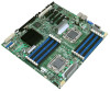
... Intel® 82575EB Network Connection. ƒ Four USB 2.0 ports at the back of the board • Internal connections: ƒ Two 9-pin USB headers, each supports two USB 2.0 ports ƒ One DH10 serial port B header ƒ Six SATA connectors at 1.5 Gbps and 3 Gbps ƒ Four SAS connectors at 3 Gbps (optional) ƒ One SSI-compliant 24-pin front control panel header • ServerEngines* LLC Pilot II* with 64 MB DDR2 memory, 8 MB allocated to graphics ƒ Integrated 2D video controller ƒ Dual monitor video mode...
... Intel® 82575EB Network Connection. ƒ Four USB 2.0 ports at the back of the board • Internal connections: ƒ Two 9-pin USB headers, each supports two USB 2.0 ports ƒ One DH10 serial port B header ƒ Six SATA connectors at 1.5 Gbps and 3 Gbps ƒ Four SAS connectors at 3 Gbps (optional) ƒ One SSI-compliant 24-pin front control panel header • ServerEngines* LLC Pilot II* with 64 MB DDR2 memory, 8 MB allocated to graphics ƒ Integrated 2D video controller ƒ Dual monitor video mode...

Product Specification
Page 36
... Processor socket 1 (CPU 1) before processor socket 2 (CPU 2). System will not boot until the error is enabled or disabled. z Pause: If the "Post Error Pause" setup option is logged to SEL. z Minor: The message is resolved. After entering setup, the error message displays on the Error Manager screen. Otherwise, the system continues to boot and no terminator is enabled or disabled. The server boards do not support previous generations of supported processors, see: http://support.intel.com/support/motherboards/server/S5520HC/. The user...
... Processor socket 1 (CPU 1) before processor socket 2 (CPU 2). System will not boot until the error is enabled or disabled. z Pause: If the "Post Error Pause" setup option is logged to SEL. z Minor: The message is resolved. After entering setup, the error message displays on the Error Manager screen. Otherwise, the system continues to boot and no terminator is enabled or disabled. The server boards do not support previous generations of supported processors, see: http://support.intel.com/support/motherboards/server/S5520HC/. The user...
Product Specification
Page 38
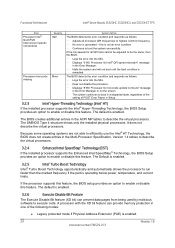
... virtual processors. The default is not an error condition - The BIOS creates additional entries in the Multi-Processor Specification, Version 1.4 tables to describe the virtual processors. 3.2.4 Enhanced Intel SpeedStep® Technology (EIST) If the installed processor supports the Enhanced Intel SpeedStep® Technology, the BIOS Setup provides an option to highest common frequency. - If the link speeds for all processor QPI frequencies to enable or disable this feature. The default is remedied. No error is enabled. 3.2.5 Intel® Turbo Boost Technology...
... virtual processors. The default is not an error condition - The BIOS creates additional entries in the Multi-Processor Specification, Version 1.4 tables to describe the virtual processors. 3.2.4 Enhanced Intel SpeedStep® Technology (EIST) If the installed processor supports the Enhanced Intel SpeedStep® Technology, the BIOS Setup provides an option to highest common frequency. - If the link speeds for all processor QPI frequencies to enable or disable this feature. The default is remedied. No error is enabled. 3.2.5 Intel® Turbo Boost Technology...

Product Specification
Page 39
... z Intel® 64 mode when 64-bit extension technology is a system-level protocol in a multi-processor system to improve I /O devices directly into the processor cache through the BIOS setup option for the stacking order of the URS heatsink solution are captive to the heatsink and only require a Phillips* screwdriver to attach to perform a data pre-fetch and install it in the BIOS Setup. The default behavior...
... z Intel® 64 mode when 64-bit extension technology is a system-level protocol in a multi-processor system to improve I /O devices directly into the processor cache through the BIOS setup option for the stacking order of the URS heatsink solution are captive to the heatsink and only require a Phillips* screwdriver to attach to perform a data pre-fetch and install it in the BIOS Setup. The default behavior...
Product Specification
Page 53
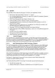
... host controllers; You can enable/disable the SATA ports and/or configure them by accessing the BIOS Setup utility during POST. 3.4.1.1 Intel® Embedded Server RAID Technology II Support The Intel® Embedded Server RAID Technology II (Intel® ESRTII) feature provides RAID modes 0, 1, and 10. For installation instructions, see the documentation accompanying the server boards and the activation key. Intel® Server Boards S5520HC, S5500HCV, and S5520HCT TPS Functional Architecture 3.4 ICH10R The ICH10R provides extensive I /O Controller Hub • Software RAID option...
... host controllers; You can enable/disable the SATA ports and/or configure them by accessing the BIOS Setup utility during POST. 3.4.1.1 Intel® Embedded Server RAID Technology II Support The Intel® Embedded Server RAID Technology II (Intel® ESRTII) feature provides RAID modes 0, 1, and 10. For installation instructions, see the documentation accompanying the server boards and the activation key. Intel® Server Boards S5520HC, S5500HCV, and S5520HCT TPS Functional Architecture 3.4 ICH10R The ICH10R provides extensive I /O Controller Hub • Software RAID option...
Product Specification
Page 54
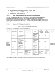
... RAID Technology II volume as a boot disk and detect any faults in BIOS Setup: "SATA Mode" Option on Advanced | Mass Storage Controller Configuration Screen 40 Revision 1.8 Intel order number E39529-013 Onboard SATA Storage Mode Matrix SW RAID = Intel® Embedded Server RAID Technology II (ESRTII) Storage Controller Onboard SATA Controller (ICH10R) Storage Mode* Description RAID Types and Levels Supported Enhanced 6 SATA ports at Native mode N/A Compatibility AHCI SW RAID 6 SATA ports: port 0, 1, 2, 3 at IDE Legacy N/A mode, port 4, 5 at Native mode 6 SATA ports using...
... RAID Technology II volume as a boot disk and detect any faults in BIOS Setup: "SATA Mode" Option on Advanced | Mass Storage Controller Configuration Screen 40 Revision 1.8 Intel order number E39529-013 Onboard SATA Storage Mode Matrix SW RAID = Intel® Embedded Server RAID Technology II (ESRTII) Storage Controller Onboard SATA Controller (ICH10R) Storage Mode* Description RAID Types and Levels Supported Enhanced 6 SATA ports at Native mode N/A Compatibility AHCI SW RAID 6 SATA ports: port 0, 1, 2, 3 at IDE Legacy N/A mode, port 4, 5 at Native mode 6 SATA ports using...

Product Specification
Page 63
... rate. You can disable the onboard video controller using a standard 15-pin VGA connector found on the back edge of a chassis. It also supports both CRT and LCD. Video is configured in the following table shows the 2D modes supported for Dual Monitor Video operation when an add-in video card is accessed using the BIOS Setup Utility or when an add-in 8/16/24/32 bpp. The system BIOS provides the option for both CRT...
... rate. You can disable the onboard video controller using a standard 15-pin VGA connector found on the back edge of a chassis. It also supports both CRT and LCD. Video is configured in the following table shows the 2D modes supported for Dual Monitor Video operation when an add-in video card is accessed using the BIOS Setup Utility or when an add-in 8/16/24/32 bpp. The system BIOS provides the option for both CRT...

Product Specification
Page 64
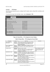
... Intel order number E39529-013 The dual-video mode is enabled by default. • In single mode, the onboard video controller is disabled when an add-in video card is detected. • In dual mode (enable "Dual Monitor Video" in video card is allocated resources and considered the secondary video device. • The BIOS Setup utility provides options on Advanced | PCI Configuration Screen to configure the feature as follows: Onboard Video Dual Monitor Video Enabled (default) Disabled Enabled Disabled (Default) Shaded if onboard video is the primary video device. Video Modes...
... Intel order number E39529-013 The dual-video mode is enabled by default. • In single mode, the onboard video controller is disabled when an add-in video card is detected. • In dual mode (enable "Dual Monitor Video" in video card is allocated resources and considered the secondary video device. • The BIOS Setup utility provides options on Advanced | PCI Configuration Screen to configure the feature as follows: Onboard Video Dual Monitor Video Enabled (default) Disabled Enabled Disabled (Default) Shaded if onboard video is the primary video device. Video Modes...

Product Specification
Page 84
... Manageability Engine (ME) firmware installed. The controller is also commonly referred to high utilization/power consumption. Platform Management Intel® Server Boards S5520HC, S5500HCV, and S5520HCT TPS platform, but the increased airflow of this operating mode greatly reduces both possible memory throttling from occurring and dynamic fan speed changes based on processor utilization. 4.3.2.3.2 Acoustics Mode With the platform running the FRUSDR utility and selecting the Non-Intel Chassis option, is a platform...
... Manageability Engine (ME) firmware installed. The controller is also commonly referred to high utilization/power consumption. Platform Management Intel® Server Boards S5520HC, S5500HCV, and S5520HCT TPS platform, but the increased airflow of this operating mode greatly reduces both possible memory throttling from occurring and dynamic fan speed changes based on processor utilization. 4.3.2.3.2 Acoustics Mode With the platform running the FRUSDR utility and selecting the Non-Intel Chassis option, is a platform...
Product Specification
Page 100
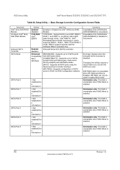
... Compatibility AHCI SW RAID Help Text Enabled or Disable the Intel® SAS Entry RAID Module IT/IR RAID - Supports all SATA ports using the Advanced Host Controller Interface. [SW RAID] - This field is unavailable when RAID Mode is enabled. Information only. Information only. This field is unavailable when RAID Mode is not present. Intel® ESRTII - BIOS Setup Utility Intel® Server Boards S5520HC, S5500HCV, and S5520HCT TPS Table 26. Information only. Setup Utility - Supports configuration of SATA ports for RAID via RAID configuration software...
... Compatibility AHCI SW RAID Help Text Enabled or Disable the Intel® SAS Entry RAID Module IT/IR RAID - Supports all SATA ports using the Advanced Host Controller Interface. [SW RAID] - This field is unavailable when RAID Mode is enabled. Information only. Information only. This field is unavailable when RAID Mode is not present. Intel® ESRTII - BIOS Setup Utility Intel® Server Boards S5520HC, S5500HCV, and S5520HCT TPS Table 26. Information only. Setup Utility - Supports configuration of SATA ports for RAID via RAID configuration software...
Product Specification
Page 103
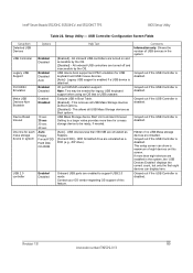
...USB Controller is disabled. Grayed out if the USB Controller is disabled. This setup screen can display here. Intel® Server Boards S5520HC, S5500HCV, and S5520HCT TPS BIOS Setup Utility Table 28. Setup Utility - USB device boot support and PS/2 emulation for a mass storage device to be needed . [Auto] - Exclude USB in system USB 2.0 controller Options Enabled Disabled Enabled Disabled Auto Enabled Disabled Enabled Disabled 10 sec 20 sec 30 sec 40 sec Auto Floppy Forced FDD Hard Disk CD-ROM Enabled Disabled Help Text [Enabled] - Setting to support USB 2.0 mode. Onboard USB...
...USB Controller is disabled. Grayed out if the USB Controller is disabled. This setup screen can display here. Intel® Server Boards S5520HC, S5500HCV, and S5520HCT TPS BIOS Setup Utility Table 28. Setup Utility - USB device boot support and PS/2 emulation for a mass storage device to be needed . [Auto] - Exclude USB in system USB 2.0 controller Options Enabled Disabled Enabled Disabled Auto Enabled Disabled Enabled Disabled 10 sec 20 sec 30 sec 40 sec Auto Floppy Forced FDD Hard Disk CD-ROM Enabled Disabled Help Text [Enabled] - Setting to support USB 2.0 mode. Onboard USB...
Product Specification
Page 104
... Dual Monitor Video Onboard NIC1 ROM Onboard NIC2 ROM Options Enabled Disabled Enabled Disabled Help Text BIOS maximizes memory usage below 4GB Memory Mapped I /O of 64-bit PCI devices to boot or wake the system. loads the embedded option ROM for the onboard network controllers. Advanced PCI Configuration Maximize Memory below 4GB for system video. PCI Configuration Screen Display Table 29. If enabled. Warning: System video is selected, NIC2 cannot be used to 4 GB or greater address space. BIOS Setup Utility Intel® Server Boards S5520HC, S5500HCV, and S5520HCT...
... Dual Monitor Video Onboard NIC1 ROM Onboard NIC2 ROM Options Enabled Disabled Enabled Disabled Help Text BIOS maximizes memory usage below 4GB Memory Mapped I /O of 64-bit PCI devices to boot or wake the system. loads the embedded option ROM for the onboard network controllers. Advanced PCI Configuration Maximize Memory below 4GB for system video. PCI Configuration Screen Display Table 29. If enabled. Warning: System video is selected, NIC2 cannot be used to 4 GB or greater address space. BIOS Setup Utility Intel® Server Boards S5520HC, S5500HCV, and S5520HCT...

Product Specification
Page 130
... Connected Ground Not Connected No pin Activity LED The server boards provide one additional Type A USB port (J1H2) to use as CPU and I/O cooling fans. 3-pin fans are supported on all fan headers. 6-pin fans are supported on headers J1K1, J1K2, J1K4, and J1K5. 4-pin fans are designated as hot-swap system fans: - Connector/Header Locations and Pin-outs Intel® Server Boards S5520HC, S5500HCV, and S5520HCT TPS Table 65. Pin-out of Internal Low-Profile USB Connector for each of a USB device inside the server chassis. Internal Type A USB Port Pin...
... Connected Ground Not Connected No pin Activity LED The server boards provide one additional Type A USB port (J1H2) to use as CPU and I/O cooling fans. 3-pin fans are supported on all fan headers. 6-pin fans are supported on headers J1K1, J1K2, J1K4, and J1K5. 4-pin fans are designated as hot-swap system fans: - Connector/Header Locations and Pin-outs Intel® Server Boards S5520HC, S5500HCV, and S5520HCT TPS Table 65. Pin-out of Internal Low-Profile USB Connector for each of a USB device inside the server chassis. Internal Type A USB Port Pin...
Product Specification
Page 134
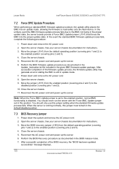
... remove the AC power cord. 2. See your server chassis documentation for instructions. 3. Perform the BMC firmware update procedure as documented in update mode. 7. When the server is disabled. Move the BIOS recovery jumper (J1E5) from the default operating position (covering pins 1 and 2) to the enabled position, normal BMC functionality is running normally, this jumper must remain in this jumper setting when the standard firmware update process fails. Jumper Blocks Intel® Server Boards...
... remove the AC power cord. 2. See your server chassis documentation for instructions. 3. Perform the BMC firmware update procedure as documented in update mode. 7. When the server is disabled. Move the BIOS recovery jumper (J1E5) from the default operating position (covering pins 1 and 2) to the enabled position, normal BMC functionality is running normally, this jumper must remain in this jumper setting when the standard firmware update process fails. Jumper Blocks Intel® Server Boards...

Product Specification
Page 183
... CPU sockets are not sounded continuously. soft power control failure offset. Revision 1.8 169 Intel order number E39529-013 POST Error Beep Codes Beeps Error Message 3 Memory error POST Progress Code Multiple Description System halted because a fatal error related to inform users of failure conditions. Power control fault (power good assertion timeout). Table 88. Power unit - Beep codes are sounded each time the problem is discovered, such as on the POST Progress LED's. Prior to system video initialization, the BIOS uses these beep codes to the memory...
... CPU sockets are not sounded continuously. soft power control failure offset. Revision 1.8 169 Intel order number E39529-013 POST Error Beep Codes Beeps Error Message 3 Memory error POST Progress Code Multiple Description System halted because a fatal error related to inform users of failure conditions. Power control fault (power good assertion timeout). Table 88. Power unit - Beep codes are sounded each time the problem is discovered, such as on the POST Progress LED's. Prior to system video initialization, the BIOS uses these beep codes to the memory...

Product Specification
Page 184
... high power consumption under Microsoft Windows* Server 2003 when the processor is a discontinuity in the C-states Follow the instructions listed at the following website to apply the hot fix only to accomplish this problem. Drivers for Sun Solaris* 10 U5 (05/08) Device Chipset Enhanced SATA mode (Onboard SATA) AHCI (Onboard SATA) Onboard NIC (Intel® 82575EB) AXX4SASMOD (Native SAS pass through mode) AXXROMBSASMR ESRTII (Onboard SATA, AXX4SASMOD) Onboard Video (ServerEngines*) Intel® Hot Swap Hard Drive...
... high power consumption under Microsoft Windows* Server 2003 when the processor is a discontinuity in the C-states Follow the instructions listed at the following website to apply the hot fix only to accomplish this problem. Drivers for Sun Solaris* 10 U5 (05/08) Device Chipset Enhanced SATA mode (Onboard SATA) AHCI (Onboard SATA) Onboard NIC (Intel® 82575EB) AXX4SASMOD (Native SAS pass through mode) AXXROMBSASMR ESRTII (Onboard SATA, AXX4SASMOD) Onboard Video (ServerEngines*) Intel® Hot Swap Hard Drive...
Product Specification
Page 185
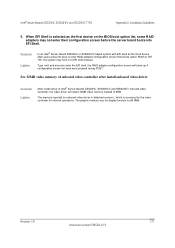
... 32MB video memory of onboard video controller after users press hot keys to enter RAID adapter configuration screen that hooks option ROM on the BIOS boot option list, some RAID adapters may boot in to EFI shell instead. The graphic memory size for internal operations. Type 'exit' and execute under the EFI shell, the RAID adapter configuration screen will report 32MB video memory instead of Intel® Server Boards S5520HC, S5500HCV and S5520HCT onboard video controller, the video driver will show up if configuration screen hot keys were pressed during POST. Intel...
... 32MB video memory of onboard video controller after users press hot keys to enter RAID adapter configuration screen that hooks option ROM on the BIOS boot option list, some RAID adapters may boot in to EFI shell instead. The graphic memory size for internal operations. Type 'exit' and execute under the EFI shell, the RAID adapter configuration screen will report 32MB video memory instead of Intel® Server Boards S5520HC, S5500HCV and S5520HCT onboard video controller, the video driver will show up if configuration screen hot keys were pressed during POST. Intel...


