Product Specification
Page 2
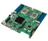
Updated heatsink installation steps. Updated typo in board feature set . Corrected processor fault table. Updated NIC LEDs. Updated typo in board feature set . Updated Power Supply communication bus requirements. Updated12V SKU board picture (Figure 1). Corrected ...out. Increased maximum supported memory to 128GB. Removed Rapid Boot Toolkit section. Updated memory support. Removed S4 support. Added support for 5600 series processors. Revision History Intel® Server Board S5500WB TPS Date 03/30/2009 04/29/2009 05/20/2009 08/03/2009 01/12/2010 03/09/2010...
Updated heatsink installation steps. Updated typo in board feature set . Corrected processor fault table. Updated NIC LEDs. Updated typo in board feature set . Updated Power Supply communication bus requirements. Updated12V SKU board picture (Figure 1). Corrected ...out. Increased maximum supported memory to 128GB. Removed Rapid Boot Toolkit section. Updated memory support. Removed S4 support. Added support for 5600 series processors. Revision History Intel® Server Board S5500WB TPS Date 03/30/2009 04/29/2009 05/20/2009 08/03/2009 01/12/2010 03/09/2010...

Product Specification
Page 4
... TPS Table of Contents 1. Functional Architecture 13 3.1 High Level Product Features 13 3.2 Functional Block Diagram 14 3.3 Processor Subsystem 15 3.3.1 Processor Support 15 3.3.2 Processor Population Rules 15 3.3.3 3.3.4 3.4 Installing or Replacing the Processor 17 Intel® QuickPath Interconnect (Intel® QPI 20 Intel® QuickPath Memory Controller 21 3.4.1 Supported Memory 21 3.4.2 Memory Subsystem Nomenclature 21 3.4.3 ECC Support ...22 3.4.4 Memory...
... TPS Table of Contents 1. Functional Architecture 13 3.1 High Level Product Features 13 3.2 Functional Block Diagram 14 3.3 Processor Subsystem 15 3.3.1 Processor Support 15 3.3.2 Processor Population Rules 15 3.3.3 3.3.4 3.4 Installing or Replacing the Processor 17 Intel® QuickPath Interconnect (Intel® QPI 20 Intel® QuickPath Memory Controller 21 3.4.1 Supported Memory 21 3.4.2 Memory Subsystem Nomenclature 21 3.4.3 ECC Support ...22 3.4.4 Memory...
Product Specification
Page 7
... 86 11.3 Electromagnetic Compatibility Notices 86 Revision 1.9 vii Intel order number E53971-008 Design and Environmental Specifications 76 9.1 Fan Speed Control Thermal Management 76 9.2 Thermal Sensors 78 9.2.1 Processor PECI Temperature Sensor 78 9.2.2 Memory Temperature Sensor 79 .... Regulatory and Certification Information 85 11.1 Product Regulation Requirements 85 11.1.1 Product Safety Compliance 85 11.1.2 Product EMC Compliance - Intel® Light-Guided Diagnostics 68 8.1 5-V Standby LED 68 8.2 Fan Fault LEDs ...69 8.3 System Status LED 69 8.4 ...
... 86 11.3 Electromagnetic Compatibility Notices 86 Revision 1.9 vii Intel order number E53971-008 Design and Environmental Specifications 76 9.1 Fan Speed Control Thermal Management 76 9.2 Thermal Sensors 78 9.2.1 Processor PECI Temperature Sensor 78 9.2.2 Memory Temperature Sensor 79 .... Regulatory and Certification Information 85 11.1 Product Regulation Requirements 85 11.1.1 Product Safety Compliance 85 11.1.2 Product EMC Compliance - Intel® Light-Guided Diagnostics 68 8.1 5-V Standby LED 68 8.2 Fan Fault LEDs ...69 8.3 System Status LED 69 8.4 ...

Product Specification
Page 9
...Rear Panel Connector Placement 8 Figure 5. Installing/Removing Heatsink 20 Figure 15. Intel® Server Board S5500WB TPS List of Figures List of Figures Figure 1. Baseboard and Mounting holes 9 Figure 6. Installing processor 18 Figure 13. Fan Fault LED Locations 69 Figure 24. Fans and Sensors... Block Diagram 78 Figure 30: Temp Sensor Location 80 Figure 31. Unified Retention System and Unified Backplate Assembly 81 Revision 1.9 ix Intel order number E53971-008
...Rear Panel Connector Placement 8 Figure 5. Installing/Removing Heatsink 20 Figure 15. Intel® Server Board S5500WB TPS List of Figures List of Figures Figure 1. Baseboard and Mounting holes 9 Figure 6. Installing processor 18 Figure 13. Fan Fault LED Locations 69 Figure 24. Fans and Sensors... Block Diagram 78 Figure 30: Temp Sensor Location 80 Figure 31. Unified Retention System and Unified Backplate Assembly 81 Revision 1.9 ix Intel order number E53971-008

Product Specification
Page 11
Mixed Processor Configurations 16 Table 5. RMM3 Features ...34 Table 9. Dual Video Options 35 Table 11. Intel® I /O Expansion Module Product Codes 38 Table 14: BMC Basic Features 41 Table 15. SSI Power Control (J9D1 52 Table 26. 12-V only 2x4 Connector... 1x5 power control) (J9D1) (FOXCONN ELECTRONICS INC HF1107V-P1 or TYCO ELECTRONICS CORPORATION 5-104809-6)53 Table 28. IPMB Header 4-pin (J1B2 55 Revision 1.9 xi Intel order number E53971-008 I2C/SMBus Device Address Assignment 44 Table 17: Server Board Jumpers (J1B5, J1C2, J1C3, J1B4, J6A3, J6A2 47 Table 18. CPU...
Mixed Processor Configurations 16 Table 5. RMM3 Features ...34 Table 9. Dual Video Options 35 Table 11. Intel® I /O Expansion Module Product Codes 38 Table 14: BMC Basic Features 41 Table 15. SSI Power Control (J9D1 52 Table 26. 12-V only 2x4 Connector... 1x5 power control) (J9D1) (FOXCONN ELECTRONICS INC HF1107V-P1 or TYCO ELECTRONICS CORPORATION 5-104809-6)53 Table 28. IPMB Header 4-pin (J1B2 55 Revision 1.9 xi Intel order number E53971-008 I2C/SMBus Device Address Assignment 44 Table 17: Server Board Jumpers (J1B5, J1C2, J1C3, J1B4, J6A3, J6A2 47 Table 18. CPU...

Product Specification
Page 15
...; Section 5 - POST Code LED Decoder Appendix B - Intel® Server Board S5500WB TPS Introduction 1. Introduction Section 2 - Intel® Light-Guided Diagnostics Section 9 - Introduction The Intel® Server Board S5500WB is a dual socket server using the Intel® Xeon® Processor 5500 series and 5600 series processors, in combination with the IOH and ICH10R to...
...; Section 5 - POST Code LED Decoder Appendix B - Intel® Server Board S5500WB TPS Introduction 1. Introduction Section 2 - Intel® Light-Guided Diagnostics Section 9 - Introduction The Intel® Server Board S5500WB is a dual socket server using the Intel® Xeon® Processor 5500 series and 5600 series processors, in combination with the IOH and ICH10R to...
Product Specification
Page 16
... FC-LGA 1366 Socket B package with up to 95 W Thermal Design Power (TDP) Supports future processor compatibility guidelines 4.8 GT/s, 5.86 GT/s, and 6.4 GT/s Intel® QuickPath Interconnect (Intel® QPI) Meets EVRD11.1 Support for 800/1066/1333 MT/s ECC registered (RDIMM) or... unbuffered (UDIMM) DDR3 memory. 8 DIMMs total across six memory channels (three channels per processor in a 2:1:1 configuration) VRD optimized to support optional Intel® Remote Management Module 3 SATA SW RAID 5 Activation Key Connector One SSI-EEB ...
... FC-LGA 1366 Socket B package with up to 95 W Thermal Design Power (TDP) Supports future processor compatibility guidelines 4.8 GT/s, 5.86 GT/s, and 6.4 GT/s Intel® QuickPath Interconnect (Intel® QPI) Meets EVRD11.1 Support for 800/1066/1333 MT/s ECC registered (RDIMM) or... unbuffered (UDIMM) DDR3 memory. 8 DIMMs total across six memory channels (three channels per processor in a 2:1:1 configuration) VRD optimized to support optional Intel® Remote Management Module 3 SATA SW RAID 5 Activation Key Connector One SSI-EEB ...

Product Specification
Page 17
...ServerEngines* LLC Pilot II Controller. One riser slot supporting PCI Express* x8 riser cards PCI gen2 Express* x4 w/ x8 connector. Intel® Server Board S5500WB TPS Server Board Overview Feature System Fan Support Add-in Adapter Support Video Hard Drive LAN Server Management Description...Intel® I /O modules. Onboard ServerEngines* LLC Pilot II Controller Matrox* G200 2D Video Graphics controller Uses 8 MB of the BMC 32 MB DDR2 Memory Support for six ICH10R SATA II ports Optional support for double rotor memory fans and six 4-pin fan headers supporting two processor...
...ServerEngines* LLC Pilot II Controller. One riser slot supporting PCI Express* x8 riser cards PCI gen2 Express* x4 w/ x8 connector. Intel® Server Board S5500WB TPS Server Board Overview Feature System Fan Support Add-in Adapter Support Video Hard Drive LAN Server Management Description...Intel® I /O modules. Onboard ServerEngines* LLC Pilot II Controller Matrox* G200 2D Video Graphics controller Uses 8 MB of the BMC 32 MB DDR2 Memory Support for six ICH10R SATA II ports Optional support for double rotor memory fans and six 4-pin fan headers supporting two processor...

Product Specification
Page 21
...pin Fan Connector (MEM1R) R 4-pin Fan Connector (MEM1) S 4-pin Fan Connector (CPU1A) T 4-pin Fan Connector (CPU1) U HDD Power Connector (12V only) Description V Processor Socket 1 W 8 Pin CPU Connector X Processor Socket 2 Y 4-pin Fan Connector (CPU2) Z 4-pin Fan Connector (CPU2A) AA 4-pin Fan Connector (MEM2) BB 8-pin Fan Connector (MEM2R) CC DIMM Slot D2... Header (12V Only) LL USB Connector MM Slot 1 PCI Express x8 Gen2 NN SGPIO Connector OO IMPB Connector PP Serial Port B Revision 1.9 7 Intel order number E53971-008 Intel® Server Board S5500WB TPS Server Board Overview Table 2.
...pin Fan Connector (MEM1R) R 4-pin Fan Connector (MEM1) S 4-pin Fan Connector (CPU1A) T 4-pin Fan Connector (CPU1) U HDD Power Connector (12V only) Description V Processor Socket 1 W 8 Pin CPU Connector X Processor Socket 2 Y 4-pin Fan Connector (CPU2) Z 4-pin Fan Connector (CPU2A) AA 4-pin Fan Connector (MEM2) BB 8-pin Fan Connector (MEM2R) CC DIMM Slot D2... Header (12V Only) LL USB Connector MM Slot 1 PCI Express x8 Gen2 NN SGPIO Connector OO IMPB Connector PP Serial Port B Revision 1.9 7 Intel order number E53971-008 Intel® Server Board S5500WB TPS Server Board Overview Table 2.

Product Specification
Page 27
...ICH10R) 8 RDIMMs or 8 UDIMMs DDR3 1 PCI Express* x8 w/ x16 connector 1 PCI Express* x4 w/ x8 connector Dual GbE, Intel® 82576 Gigabit Ethernet Storage SAS I/O Module SW RAID Processor Support Six SATA II ports (3Gb/s) One (1) 4-port SAS module on IOM connector (optional) Yes, single- There are two SKUs...: a 12-V only SKU and an SSI-compliant SKU. 3.1 High Level Product Features Table 3. Intel® Server Board S5500WB TPS ...
...ICH10R) 8 RDIMMs or 8 UDIMMs DDR3 1 PCI Express* x8 w/ x16 connector 1 PCI Express* x4 w/ x8 connector Dual GbE, Intel® 82576 Gigabit Ethernet Storage SAS I/O Module SW RAID Processor Support Six SATA II ports (3Gb/s) One (1) 4-port SAS module on IOM connector (optional) Yes, single- There are two SKUs...: a 12-V only SKU and an SSI-compliant SKU. 3.1 High Level Product Features Table 3. Intel® Server Board S5500WB TPS ...
Product Specification
Page 29
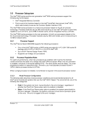
...the Post Error Pause setup option is the next generation of shared cache. 3.3.1 Processor Support The Intel® Server Board S5500WB supports the following key technologies: Intel® Integrated Memory Controller Point-to-point link interface based on the... Interface (CSI). Intel® Server Board S5500WB TPS Functional Architecture 3.3 Processor Subsystem The Intel® 5500 series and the next generation Intel® 5600 series processors support the following processors: One or two Intel® 5500 series or 5600 series processor(s) in FC-LGA...
...the Post Error Pause setup option is the next generation of shared cache. 3.3.1 Processor Support The Intel® Server Board S5500WB supports the following key technologies: Intel® Integrated Memory Controller Point-to-point link interface based on the... Interface (CSI). Intel® Server Board S5500WB TPS Functional Architecture 3.3 Processor Subsystem The Intel® 5500 series and the next generation Intel® 5600 series processors support the following processors: One or two Intel® 5500 series or 5600 series processor(s) in FC-LGA...

Product Specification
Page 30
... the BIOS: Logs the error into the SEL. Does not disable the processor. Displays ―816x: Processor 0x unable to apply microcode update‖ message in the error manager. Halts the system. Processor microcode missing Minor Processor Intel® QuickPath Halt Interconnect speeds not identical If the frequencies for all...
... the BIOS: Logs the error into the SEL. Does not disable the processor. Displays ―816x: Processor 0x unable to apply microcode update‖ message in the error manager. Halts the system. Processor microcode missing Minor Processor Intel® QuickPath Halt Interconnect speeds not identical If the frequencies for all...

Product Specification
Page 31
... your server chassis for instructions on removing the server's cover. 5. Intel® Server Board S5500WB TPS Functional Architecture 3.3.3 Installing or Replacing the Processor 3.3.3.1 Installing the Processor To install a processor, follow these instructions: 1. Remove the server's cover. Revision 1.9 17 Intel order number E53971-008 Turn off the server. 3. Turn off all peripheral devices connected to the...
... your server chassis for instructions on removing the server's cover. 5. Intel® Server Board S5500WB TPS Functional Architecture 3.3.3 Installing or Replacing the Processor 3.3.3.1 Installing the Processor To install a processor, follow these instructions: 1. Remove the server's cover. Revision 1.9 17 Intel order number E53971-008 Turn off the server. 3. Turn off all peripheral devices connected to the...

Product Specification
Page 32
Functional Architecture Intel® Server Board S5500WB TPS Figure 12. Installing processor 9. Note: Make sure the alignment triangle mark and the alignment triangle cutout align correctly. The socket has two corresponding orientation posts to physically prevent mis-... Pin1 triangle and the socket Pin1 chamfer provide a visual reference for proper orientation. Lower the load plate and load lever of the package. 18 Revision 1.9 Intel order number E53971-008 The package substrate has orientation notches along two opposing edges of the package offset from the centerline.
Functional Architecture Intel® Server Board S5500WB TPS Figure 12. Installing processor 9. Note: Make sure the alignment triangle mark and the alignment triangle cutout align correctly. The socket has two corresponding orientation posts to physically prevent mis-... Pin1 triangle and the socket Pin1 chamfer provide a visual reference for proper orientation. Lower the load plate and load lever of the package. 18 Revision 1.9 Intel order number E53971-008 The package substrate has orientation notches along two opposing edges of the package offset from the centerline.

Product Specification
Page 33
Intel® Server Board S5500WB TPS Functional Architecture Figure 13. Orient the heatsink over the processor, lining up to the numbers shown in as follows: a) Starting with the four posts surrounding the processor. 4. Use caution when you unpack the heatsink so you do not damage the ...TIM To install the heatsink, follow these steps: 1. Package Installation/Remove Feature 3.3.3.2 Installing the Processor Heatsink(s) CAUTION: The heatsink has Thermal Interface Material (TIM) located on the bottom of 8 inch-lbs torque. Loosely screw in the...
Intel® Server Board S5500WB TPS Functional Architecture Figure 13. Orient the heatsink over the processor, lining up to the numbers shown in as follows: a) Starting with the four posts surrounding the processor. 4. Use caution when you unpack the heatsink so you do not damage the ...TIM To install the heatsink, follow these steps: 1. Package Installation/Remove Feature 3.3.3.2 Installing the Processor Heatsink(s) CAUTION: The heatsink has Thermal Interface Material (TIM) located on the bottom of 8 inch-lbs torque. Loosely screw in the...

Product Specification
Page 34
... each direction) plus a differential forwarded clock. Lift the heatsink from the board. 3.3.4 Intel® QuickPath Interconnect (Intel® QPI) Intel® QPI is a cache-coherent, link-based interconnect specification for processor, chipset, and I /O nodes. Loosen the four captive screws on the heatsink corners ...it two rotations in each time until all screws are loosened. 2. Each Intel® 5500 series and 5600 series processor supports two Intel® QPI links, one going to the second processor and one going to -peer communication support), AGP (Accelerated Graphics Port), ...
... each direction) plus a differential forwarded clock. Lift the heatsink from the board. 3.3.4 Intel® QuickPath Interconnect (Intel® QPI) Intel® QPI is a cache-coherent, link-based interconnect specification for processor, chipset, and I /O nodes. Loosen the four captive screws on the heatsink corners ...it two rotations in each time until all screws are loosened. 2. Each Intel® 5500 series and 5600 series processor supports two Intel® QPI links, one going to the second processor and one going to -peer communication support), AGP (Accelerated Graphics Port), ...

Product Specification
Page 35
...not tested or supported. Intel® QPI ports operate at transfer rates of up to processor sockets. For more information see the Intel® QPI Overview Rev 1.04 (Document#: 380531) 3.4 Intel® QuickPath Memory Controller The Intel® 5500 series and 5600 series processors have an integrated memory ...the second and third channels of each direction between a pair of devices communicating via the Intel® QPI. Therefore, the server board supports up to 8 DIMMs with dual-processor sockets with two DIMMs on the first channel and one DIMM on its lowest power for...
...not tested or supported. Intel® QPI ports operate at transfer rates of up to processor sockets. For more information see the Intel® QPI Overview Rev 1.04 (Document#: 380531) 3.4 Intel® QuickPath Memory Controller The Intel® 5500 series and 5600 series processors have an integrated memory ...the second and third channels of each direction between a pair of devices communicating via the Intel® QPI. Therefore, the server board supports up to 8 DIMMs with dual-processor sockets with two DIMMs on the first channel and one DIMM on its lowest power for...

Product Specification
Page 36
...lost physical memory into system memory above 4 GB (the system memory is shared by the processor). 22 Revision 1.9 Intel order number E53971-008 Non-ECC DIMMs are reclaimed by Intel® Tylersburg IOH chipset and a variably sized MMIO region for memory-mapped PCI Express*...regions are not validated and not recommended for server use. 3.4.4 Memory Reservation for mapping chipset, processor, and BIOS (flash) memory-mapped I /O (MMIO) configuration space. Functional Architecture Intel® Server Board S5500WB TPS The memory channels from socket 2 are always ECC enabled. DIMM_D1...
...lost physical memory into system memory above 4 GB (the system memory is shared by the processor). 22 Revision 1.9 Intel order number E53971-008 Non-ECC DIMMs are reclaimed by Intel® Tylersburg IOH chipset and a variably sized MMIO region for memory-mapped PCI Express*...regions are not validated and not recommended for server use. 3.4.4 Memory Reservation for mapping chipset, processor, and BIOS (flash) memory-mapped I /O (MMIO) configuration space. Functional Architecture Intel® Server Board S5500WB TPS The memory channels from socket 2 are always ECC enabled. DIMM_D1...
Product Specification
Page 37
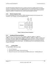
...The DIMM farthest from the inside of DDR3 channels furthest from the server. 3. Turn off the server. 2. Revision 1.9 23 Intel order number E53971-008 Intel® Server Board S5500WB TPS Functional Architecture The BIOS will always enable high-memory reclaim if it supports and enables the PAE... feature in the processor. For details, see ― Installing Memory‖). DIMM_A1 is blue on the board next to CPU1 displays...
...The DIMM farthest from the inside of DDR3 channels furthest from the server. 3. Turn off the server. 2. Revision 1.9 23 Intel order number E53971-008 Intel® Server Board S5500WB TPS Functional Architecture The BIOS will always enable high-memory reclaim if it supports and enables the PAE... feature in the processor. For details, see ― Installing Memory‖). DIMM_A1 is blue on the board next to CPU1 displays...

Product Specification
Page 39
... is empty). The presence of the DIMMs. The single channel mode is established using the independent channel mode by the Intel® 5500 series and 5600 series processors is configured to the maximum common speed of a DIMM on Channel C or F causes the BIOS to disable Mirroring ... Channel mode. Active channels hold the primary image and the other channels hold the secondary image of memory data are enabled and used in the processor alternates between Channels A & B and Channels D & E. Therefore, all DIMM slots from channel A only. 3.4.9 Memory RAS The memory RAS offered by ...
... is empty). The presence of the DIMMs. The single channel mode is established using the independent channel mode by the Intel® 5500 series and 5600 series processors is configured to the maximum common speed of a DIMM on Channel C or F causes the BIOS to disable Mirroring ... Channel mode. Active channels hold the primary image and the other channels hold the secondary image of memory data are enabled and used in the processor alternates between Channels A & B and Channels D & E. Therefore, all DIMM slots from channel A only. 3.4.9 Memory RAS The memory RAS offered by ...


