Product Guide
Page 5
...and PCI Express* Auto Configuration 19 Security Passwords 19 Hardware Management 20 Hardware Monitoring and Fan Speed Control 20 Intel® Precision Cooling Technology 20 Chassis Intrusion 20 Power Management 21 Software Support 21 ACPI 21 Hardware Support 21 Power Connectors 21 Fan Headers 22 ... 25 Onboard VR and CPU LEDs 27 Speaker...28 Battery ...28 Real-Time Clock 28 2 Installing and Replacing Desktop Board Components Before You Begin 29 Installation Precautions 30 Prevent Power Supply Overload 30 Observe Safety and Regulatory Requirements 30 Installing the I/O Shield ...
...and PCI Express* Auto Configuration 19 Security Passwords 19 Hardware Management 20 Hardware Monitoring and Fan Speed Control 20 Intel® Precision Cooling Technology 20 Chassis Intrusion 20 Power Management 21 Software Support 21 ACPI 21 Hardware Support 21 Power Connectors 21 Fan Headers 22 ... 25 Onboard VR and CPU LEDs 27 Speaker...28 Battery ...28 Real-Time Clock 28 2 Installing and Replacing Desktop Board Components Before You Begin 29 Installation Precautions 30 Prevent Power Supply Overload 30 Observe Safety and Regulatory Requirements 30 Installing the I/O Shield ...
Product Guide
Page 6
Intel Desktop Board D5400XS Product Guide Installing and Removing the Desktop Board 32 Installing a Processor 33 Installing a Processor 33 Installing a Processor Fan Heat Sink 37 Installing an MCH Heat Sink Fan (Optional 38 Installing and Removing ...to the Flexible Audio System 52 Connecting Chassis Fan and Power Supply Cables 53 Connecting Chassis Fan Cables 53 Connecting Power Supply Cables 54 Setting the BIOS Configuration Jumper 55 Clearing Passwords 56 Replacing the Battery 57 3 Updating the BIOS Updating the BIOS with the Intel® Express BIOS Update Utility 63 Updating...
Intel Desktop Board D5400XS Product Guide Installing and Removing the Desktop Board 32 Installing a Processor 33 Installing a Processor 33 Installing a Processor Fan Heat Sink 37 Installing an MCH Heat Sink Fan (Optional 38 Installing and Removing ...to the Flexible Audio System 52 Connecting Chassis Fan and Power Supply Cables 53 Connecting Chassis Fan Cables 53 Connecting Power Supply Cables 54 Setting the BIOS Configuration Jumper 55 Clearing Passwords 56 Replacing the Battery 57 3 Updating the BIOS Updating the BIOS with the Intel® Express BIOS Update Utility 63 Updating...
Product Guide
Page 7
... of Hazardous Substances (RoHS 83 EU RoHS 83 China RoHS 84 EMC Regulations 86 Ensure Electromagnetic Compatibility (EMC) Compliance 87 Product Certifications 88 Board-Level Certification Markings 88 Chassis and Component Certifications 89 Figures 1. Installing a PCI Express x16 Card 42 20. Connecting Serial ATA Cables 46 23. Internal Headers and Connectors 47...
... of Hazardous Substances (RoHS 83 EU RoHS 83 China RoHS 84 EMC Regulations 86 Ensure Electromagnetic Compatibility (EMC) Compliance 87 Product Certifications 88 Board-Level Certification Markings 88 Chassis and Component Certifications 89 Figures 1. Installing a PCI Express x16 Card 42 20. Connecting Serial ATA Cables 46 23. Internal Headers and Connectors 47...

Product Guide
Page 8
... 30. IEEE 1394a Header Signal Names 49 8. Back Panel CIR Header Emitter (Output) Header Signal Names 51 12. EMC Regulations 86 21. Intel Desktop Board D5400XS Product Guide 28. Chassis Intrusion Header Signal Names 48 6. Front Panel Audio Header Signal Names 49 7. Beep Codes 71 15. BIOS Error Messages 71 16. HD Audio...
... 30. IEEE 1394a Header Signal Names 49 8. Back Panel CIR Header Emitter (Output) Header Signal Names 51 12. EMC Regulations 86 21. Intel Desktop Board D5400XS Product Guide 28. Chassis Intrusion Header Signal Names 48 6. Front Panel Audio Header Signal Names 49 7. Beep Codes 71 15. BIOS Error Messages 71 16. HD Audio...
Product Guide
Page 12
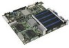
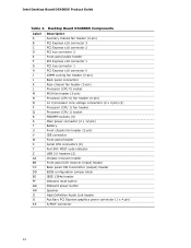
Intel Desktop Board D5400XS Product Guide Table 2. Desktop Board D5400XS Components Label A B C D E F G H I J K L M N O P Q R S T U V W X Y Z AA BB CC DD EE FF GG HH II JJ KK Description Auxiliary chassis fan header (4-pin) PCI Express x16 connector 3 PCI Express x16 connector 2 PCI bus connector...panel audio header PCI Express x16 connector 1 PCI bus connector 1 PCI Express x16 connector 0 DIMM cooling fan header (3-pin) Back panel connectors Rear chassis fan header (3-pin) Processor (CPU 0) socket MCH fan header (3-pin) Processor (CPU 0) fan header (4-pin) 12 V processor core voltage ...
Intel Desktop Board D5400XS Product Guide Table 2. Desktop Board D5400XS Components Label A B C D E F G H I J K L M N O P Q R S T U V W X Y Z AA BB CC DD EE FF GG HH II JJ KK Description Auxiliary chassis fan header (4-pin) PCI Express x16 connector 3 PCI Express x16 connector 2 PCI bus connector...panel audio header PCI Express x16 connector 1 PCI bus connector 1 PCI Express x16 connector 0 DIMM cooling fan header (3-pin) Back panel connectors Rear chassis fan header (3-pin) Processor (CPU 0) socket MCH fan header (3-pin) Processor (CPU 0) fan header (4-pin) 12 V processor core voltage ...

Product Guide
Page 20
... fans, that can be compatible with the Wired for the location of the chassis intrusion header. 20 Chassis Intrusion The board supports a chassis security feature that can adjust fan speed or switch the fans off as needed Intel® Precision Cooling Technology Intel Precision Cooling Technology automatically adjusts processor fan speed based on the processor temperature...
... fans, that can be compatible with the Wired for the location of the chassis intrusion header. 20 Chassis Intrusion The board supports a chassis security feature that can adjust fan speed or switch the fans off as needed Intel® Precision Cooling Technology Intel Precision Cooling Technology automatically adjusts processor fan speed based on the processor temperature...

Product Guide
Page 22
...supply. The LAN subsystem monitors network traffic and upon detecting a Magic Packet* frame, it asserts a wake-up of delivering adequate +5 V standby current. Intel Desktop Board D5400XS Product Guide Fan Headers The function/operation of the fans is as follows: • The fans are on when the computer is in the... the fan speed or switch the fan on or off as needed. • All fan headers have a +12 V DC connection. The Desktop Board has two 4-pin processor fan headers, one 4-pin and two 3-pin chassis fan headers, one 3-pin MCH fan header, and one 3-pin DIMM cooling fan header.
...supply. The LAN subsystem monitors network traffic and upon detecting a Magic Packet* frame, it asserts a wake-up of delivering adequate +5 V standby current. Intel Desktop Board D5400XS Product Guide Fan Headers The function/operation of the fans is as follows: • The fans are on when the computer is in the... the fan speed or switch the fan on or off as needed. • All fan headers have a +12 V DC connection. The Desktop Board has two 4-pin processor fan headers, one 4-pin and two 3-pin chassis fan headers, one 3-pin MCH fan header, and one 3-pin DIMM cooling fan header.

Product Guide
Page 25
PME# Signal Wake-up Support When the WAKE# signal on the PCI bus is intended for use of the computer chassis. Currently Intel Desktop Boards are capable of Energy and the US Environmental Protection Agency revised the ENERGY STAR requirements. The power button is asserted, the computer wakes from an... ACPI S3 state. Desktop Board Features Wake from USB NOTE Wake from USB requires the use at an ESD workstation using an antistatic wrist strap and a conductive foam pad. USB bus activity wakes the computer from an ACPI S1, S3, S4, or S5 state. Intel worked directly with these two ...
PME# Signal Wake-up Support When the WAKE# signal on the PCI bus is intended for use of the computer chassis. Currently Intel Desktop Boards are capable of Energy and the US Environmental Protection Agency revised the ENERGY STAR requirements. The power button is asserted, the computer wakes from an... ACPI S3 state. Desktop Board Features Wake from USB NOTE Wake from USB requires the use at an ESD workstation using an antistatic wrist strap and a conductive foam pad. USB bus activity wakes the computer from an ACPI S1, S3, S4, or S5 state. Intel worked directly with these two ...
Product Guide
Page 29
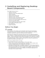
... continue to operate even though the front panel power button is not available, you open the computer or perform any of the computer chassis. 29 Some circuitry on the board can provide some ESD protection by wearing an antistatic wrist strap and attaching it to a metal part of the procedures described in...
... continue to operate even though the front panel power button is not available, you open the computer or perform any of the computer chassis. 29 Some circuitry on the board can provide some ESD protection by wearing an antistatic wrist strap and attaching it to a metal part of the procedures described in...

Product Guide
Page 30
... the instructions in this section and the instructions supplied with these instructions and the instructions provided by the chassis and module suppliers, you install or test the Intel Desktop Board, observe all warnings and cautions that the green standby power indicator (see Figure 4) is less than ...output current rating of each of the power supplies output circuits. Observe all warnings and cautions in the installation instructions. Intel Desktop Board D5400XS Product Guide Installation Precautions When you increase your computer meets safety and regulatory requirements.
... the instructions in this section and the instructions supplied with these instructions and the instructions provided by the chassis and module suppliers, you install or test the Intel Desktop Board, observe all warnings and cautions that the green standby power indicator (see Figure 4) is less than ...output current rating of each of the power supplies output circuits. Observe all warnings and cautions in the installation instructions. Intel Desktop Board D5400XS Product Guide Installation Precautions When you increase your computer meets safety and regulatory requirements.
Product Guide
Page 31
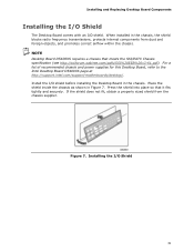
... transmissions, protects internal components from the chassis supplier. Place the shield inside the chassis as shown in the chassis. For a list of recommended chassis and power supplies for this Desktop Board, refer to the Intel Desktop Board D5400XS page at http://support.intel.com/support/motherboards/desktop/. Installing the I /O shield before installing the Desktop Board in Figure 7. If the shield...
... transmissions, protects internal components from the chassis supplier. Place the shield inside the chassis as shown in the chassis. For a list of recommended chassis and power supplies for this Desktop Board, refer to the Intel Desktop Board D5400XS page at http://support.intel.com/support/motherboards/desktop/. Installing the I /O shield before installing the Desktop Board in Figure 7. If the shield...
Product Guide
Page 32
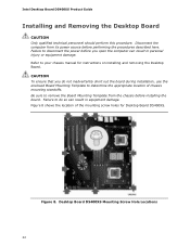
... from the chassis before installing the board. Be sure to your chassis manual for Desktop Board D5400XS. CAUTION To ensure that you open the computer can result in personal injury or equipment damage. Refer to remove the Board Mounting Template from its power source before you do so can result in equipment damage. Intel Desktop Board D5400XS...
... from the chassis before installing the board. Be sure to your chassis manual for Desktop Board D5400XS. CAUTION To ensure that you open the computer can result in personal injury or equipment damage. Refer to remove the Board Mounting Template from its power source before you do so can result in equipment damage. Intel Desktop Board D5400XS...

Product Guide
Page 42
... a PCI Express x16 Card 42 Installing a PCI Express x16 Card Follow these instructions to the chassis back panel with a screw (Figure 19, B). Place the card in a PCI Express x16 ...around the retention mechanism pin on the over-current protection of the power supply, certain Desktop Board components and/or traces may result across the connector pins. Observe the precautions in "Before You...fully seated in the connector, an electrical short may be damaged. Intel Desktop Board D5400XS Product Guide Installing and Removing PCI Express x16 Cards CAUTION When installing a PCI Express card on...
... a PCI Express x16 Card 42 Installing a PCI Express x16 Card Follow these instructions to the chassis back panel with a screw (Figure 19, B). Place the card in a PCI Express x16 ...around the retention mechanism pin on the over-current protection of the power supply, certain Desktop Board components and/or traces may result across the connector pins. Observe the precautions in "Before You...fully seated in the connector, an electrical short may be damaged. Intel Desktop Board D5400XS Product Guide Installing and Removing PCI Express x16 Cards CAUTION When installing a PCI Express card on...

Product Guide
Page 43
Push the card ejector lever down using the tip of a pencil or similar tool (Figure 20, B) in "Before You Begin" on page 29. 2. This will release the card from a connector: 1. Removing a PCI Express x16 Card 43 Remove the screw (Figure 20, A) that secures the card's metal bracket to remove a PCI Express x16 card from the connector (C). 4. Installing and Replacing Desktop Board Components Removing a PCI Express x16 Card Follow these instructions to the chassis back panel. 3. Pull the card straight up. Figure 20. Observe the precautions in the notch.
Push the card ejector lever down using the tip of a pencil or similar tool (Figure 20, B) in "Before You Begin" on page 29. 2. This will release the card from a connector: 1. Removing a PCI Express x16 Card 43 Remove the screw (Figure 20, A) that secures the card's metal bracket to remove a PCI Express x16 card from the connector (C). 4. Installing and Replacing Desktop Board Components Removing a PCI Express x16 Card Follow these instructions to the chassis back panel. 3. Pull the card straight up. Figure 20. Observe the precautions in the notch.

Product Guide
Page 47
..."Before You Begin" on Intel Desktop Board D5400XS. Item Description A HD Audio Link B S/PDIF C Front panel audio D IEEE 1394a E Front panel Item Description F USB 2.0 (2) G Front panel CIR receiver (input) H Back panel CIR emitter (output) I Chassis intrusion Figure 23. Internal... Headers and Connectors 47 Installing and Replacing Desktop Board Components Connecting to the Internal Headers and Connectors Before connecting cables to any of the internal ...
..."Before You Begin" on Intel Desktop Board D5400XS. Item Description A HD Audio Link B S/PDIF C Front panel audio D IEEE 1394a E Front panel Item Description F USB 2.0 (2) G Front panel CIR receiver (input) H Back panel CIR emitter (output) I Chassis intrusion Figure 23. Internal... Headers and Connectors 47 Installing and Replacing Desktop Board Components Connecting to the Internal Headers and Connectors Before connecting cables to any of the internal ...

Product Guide
Page 48
Table 5. Chassis Intrusion Header Signal Names Pin Description 1 Vcc 2 S/PDIF Out 3 Ground 48 This connector can be used with HDMI video cards that do not work with ... Figure 23, B shows the location of the HD Audio Link header. Table 5 shows the pin assignments and signal names for the HD Audio Link header. Intel Desktop Board D5400XS Product Guide HD Audio Link Header Figure 23, A shows the location of the S/PDIF connector. Table 4 shows the pin assignments and signal names...
Table 5. Chassis Intrusion Header Signal Names Pin Description 1 Vcc 2 S/PDIF Out 3 Ground 48 This connector can be used with HDMI video cards that do not work with ... Figure 23, B shows the location of the HD Audio Link header. Table 5 shows the pin assignments and signal names for the HD Audio Link header. Intel Desktop Board D5400XS Product Guide HD Audio Link Header Figure 23, A shows the location of the S/PDIF connector. Table 4 shows the pin assignments and signal names...

Product Guide
Page 51
... 6 Vcc 8 CIR Input Table 11. This header can be connected to a mechanical switch on the chassis to detect if the chassis cover is removed. Chassis Intrusion Header Signal Names Pin Description 1 Intruder 2 Ground 51 Table 12 shows the pin assignments and signal... names for the chassis intrusion header. Table 12. Installing and Replacing Desktop Board Components Table 10. Front Panel CIR Receiver (Input) Header Signal Names Pin Signal Name 1 Ground 3 No Connection...
... 6 Vcc 8 CIR Input Table 11. This header can be connected to a mechanical switch on the chassis to detect if the chassis cover is removed. Chassis Intrusion Header Signal Names Pin Description 1 Intruder 2 Ground 51 Table 12 shows the pin assignments and signal... names for the chassis intrusion header. Table 12. Installing and Replacing Desktop Board Components Table 10. Front Panel CIR Receiver (Input) Header Signal Names Pin Signal Name 1 Ground 3 No Connection...

Product Guide
Page 53
Figure 25. Figure 25 shows the location of the Chassis Fan Headers 53 Location of the chassis fan headers. Installing and Replacing Desktop Board Components Connecting Chassis Fan and Power Supply Cables Connecting Chassis Fan Cables Connect chassis fan cables to the 3-pin and 4-pin chassis fan headers on the Desktop Board.
Figure 25. Figure 25 shows the location of the Chassis Fan Headers 53 Location of the chassis fan headers. Installing and Replacing Desktop Board Components Connecting Chassis Fan and Power Supply Cables Connecting Chassis Fan Cables Connect chassis fan cables to the 3-pin and 4-pin chassis fan headers on the Desktop Board.
Product Guide
Page 71
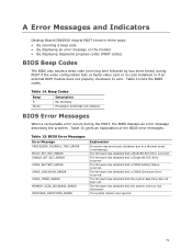
...71 The firmware has detected that a Multi-Bit ECC Error occurred. The firmware has detected that a CMOS battery failure occurred. The system chassis was previously shutdown due to zero. Beep Codes Beep 3 Siren Description No memory Processor overheat (on the monitor • By displaying ...tone followed by two short tones) during the POST, the BIOS displays an error message describing the problem. A Error Messages and Indicators Desktop Board D5400XS reports POST errors in three ways: • By sounding a beep code • By displaying an error message on reboot) BIOS...
...71 The firmware has detected that a Multi-Bit ECC Error occurred. The firmware has detected that a CMOS battery failure occurred. The system chassis was previously shutdown due to zero. Beep Codes Beep 3 Siren Description No memory Processor overheat (on the monitor • By displaying ...tone followed by two short tones) during the POST, the BIOS displays an error message describing the problem. A Error Messages and Indicators Desktop Board D5400XS reports POST errors in three ways: • By sounding a beep code • By displaying an error message on reboot) BIOS...

Product Guide
Page 77
...of Conformity statement • Product Ecology statements • Electromagnetic Compatibility (EMC) regulations • Product certifications Safety Standards Desktop Board D5400XS complies with the safety standards stated in Table 17 when correctly installed in accordance with local environmental regulations. Part 1: ... Equipment - Disposal of used batteries must be recycled where possible. A suitable caution label is insufficient space on the chassis near the battery. Safety Standards Regulation CSA/UL 60950-1, First Edition EN 60950-1:2006, Second Edition IEC 60950-1:2005,...
...of Conformity statement • Product Ecology statements • Electromagnetic Compatibility (EMC) regulations • Product certifications Safety Standards Desktop Board D5400XS complies with the safety standards stated in Table 17 when correctly installed in accordance with local environmental regulations. Part 1: ... Equipment - Disposal of used batteries must be recycled where possible. A suitable caution label is insufficient space on the chassis near the battery. Safety Standards Regulation CSA/UL 60950-1, First Edition EN 60950-1:2006, Second Edition IEC 60950-1:2005,...