Product Guide
Page 5
... Passwords 19 Hardware Management 20 Hardware Monitoring and Fan Speed Control 20 Intel® Precision Cooling Technology 20 Chassis Intrusion 20 Power Management 21 Software Support 21 ACPI 21 Hardware Support 21 Power Connectors 21 Fan Headers 22 LAN Wake Capabilities 22 Instantly Available PC ...ENERGY STAR* Capable 25 Onboard Power and Reset Buttons 25 Onboard VR and CPU LEDs 27 Speaker...28 Battery ...28 Real-Time Clock 28 2 Installing and Replacing Desktop Board Components Before You Begin 29 Installation Precautions 30 Prevent Power Supply Overload 30 Observe Safety and...
... Passwords 19 Hardware Management 20 Hardware Monitoring and Fan Speed Control 20 Intel® Precision Cooling Technology 20 Chassis Intrusion 20 Power Management 21 Software Support 21 ACPI 21 Hardware Support 21 Power Connectors 21 Fan Headers 22 LAN Wake Capabilities 22 Instantly Available PC ...ENERGY STAR* Capable 25 Onboard Power and Reset Buttons 25 Onboard VR and CPU LEDs 27 Speaker...28 Battery ...28 Real-Time Clock 28 2 Installing and Replacing Desktop Board Components Before You Begin 29 Installation Precautions 30 Prevent Power Supply Overload 30 Observe Safety and...
Product Guide
Page 6
Intel Desktop Board D5400XS Product Guide Installing and Removing the Desktop Board 32 Installing a Processor 33 Installing a Processor 33 Installing a Processor Fan Heat Sink 37 Installing an MCH Heat Sink Fan (Optional 38 Installing and Removing Memory ... 53 Connecting Chassis Fan Cables 53 Connecting Power Supply Cables 54 Setting the BIOS Configuration Jumper 55 Clearing Passwords 56 Replacing the Battery 57 3 Updating the BIOS Updating the BIOS with the Intel® Express BIOS Update Utility 63 Updating the BIOS with the ISO Image BIOS Update File or the Iflash Memory...
Intel Desktop Board D5400XS Product Guide Installing and Removing the Desktop Board 32 Installing a Processor 33 Installing a Processor 33 Installing a Processor Fan Heat Sink 37 Installing an MCH Heat Sink Fan (Optional 38 Installing and Removing Memory ... 53 Connecting Chassis Fan Cables 53 Connecting Power Supply Cables 54 Setting the BIOS Configuration Jumper 55 Clearing Passwords 56 Replacing the Battery 57 3 Updating the BIOS Updating the BIOS with the Intel® Express BIOS Update Utility 63 Updating the BIOS with the ISO Image BIOS Update File or the Iflash Memory...
Product Guide
Page 7
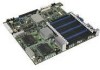
Desktop Board D5400XS Components 11 2. Disk Drive Access Indicator 18 4. Installing a DIMM 39 18. Installing a PCI Express x16 Card 42 20. Connecting the IDE Cable 45 22. Internal Headers and Connectors 47 24. Connecting Power Supply Cables 54 27. Installing the I/O Shield 31 8. Remove the Protective Socket Cover 34 12. Remove the Processor from...
Desktop Board D5400XS Components 11 2. Disk Drive Access Indicator 18 4. Installing a DIMM 39 18. Installing a PCI Express x16 Card 42 20. Connecting the IDE Cable 45 22. Internal Headers and Connectors 47 24. Connecting Power Supply Cables 54 27. Installing the I/O Shield 31 8. Remove the Protective Socket Cover 34 12. Remove the Processor from...
Product Guide
Page 13
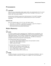
...page 33 in Chapter 2 • Supported processors for Desktop Board D5400XS, http://www.intel.com/products/motherboard/ Main Memory NOTE To be fully compliant with all applicable Intel ® SDRAM memory specifications, the board should be purchased separately. The BIOS will see a notification to... for use an appropriate power supply and/or not connecting the 12 V (2 x 4 pin) power connectors to the Desktop Board may not function properly. Related Links Go to "Installing a DIMM Cooling Fan" on the screen at power up. Desktop Board D5400XS supports two Intel processors in Chapter 2 ...
...page 33 in Chapter 2 • Supported processors for Desktop Board D5400XS, http://www.intel.com/products/motherboard/ Main Memory NOTE To be fully compliant with all applicable Intel ® SDRAM memory specifications, the board should be purchased separately. The BIOS will see a notification to... for use an appropriate power supply and/or not connecting the 12 V (2 x 4 pin) power connectors to the Desktop Board may not function properly. Related Links Go to "Installing a DIMM Cooling Fan" on the screen at power up. Desktop Board D5400XS supports two Intel processors in Chapter 2 ...

Product Guide
Page 20
... of the hardware monitoring and fan speed control include: • Monitoring of power supply voltages to the chassis intrusion header on the internal system temperature. Intel Desktop Board D5400XS Product Guide Hardware Management The hardware management features of Desktop Board D5400XS enable the board to be connected to detect levels above and below acceptable values •...
... of the hardware monitoring and fan speed control include: • Monitoring of power supply voltages to the chassis intrusion header on the internal system temperature. Intel Desktop Board D5400XS Product Guide Hardware Management The hardware management features of Desktop Board D5400XS enable the board to be connected to detect levels above and below acceptable values •...
Product Guide
Page 21
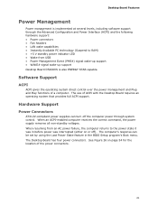
...enabled computer receives the correct command, the power supply removes all non-standby voltages. Software Support ACPI ACPI gives the operating system direct control over the power management and Plug and Play functions of ACPI with the Desktop Board requires an operating system that provides full ...; Instantly Available PC technology (Suspend to the power state it was in the BIOS Setup program's Boot menu. Hardware Support Power Connectors ATX12V-compliant power supplies can be set by using the Last Power State feature in before power was interrupted (either on page 54 for the...
...enabled computer receives the correct command, the power supply removes all non-standby voltages. Software Support ACPI ACPI gives the operating system direct control over the power management and Plug and Play functions of ACPI with the Desktop Board requires an operating system that provides full ...; Instantly Available PC technology (Suspend to the power state it was in the BIOS Setup program's Boot menu. Hardware Support Power Connectors ATX12V-compliant power supplies can be set by using the Last Power State feature in before power was interrupted (either on page 54 for the...

Product Guide
Page 22
Intel Desktop Board D5400XS Product Guide Fan Headers The function/operation of the fans is as follows: &#... state. • The fans are off as needed. • All fan headers have a +12 V DC connection. The Desktop Board has two 4-pin processor fan headers, one 4-pin and two 3-pin chassis fan headers, one 3-pin MCH fan header, and one...the hardware monitoring and control device. • All fan headers support closed-loop fan control that powers up signal that can damage the power supply. Failure to provide adequate standby current when using this feature can adjust the fan speed or switch...
Intel Desktop Board D5400XS Product Guide Fan Headers The function/operation of the fans is as follows: &#... state. • The fans are off as needed. • All fan headers have a +12 V DC connection. The Desktop Board has two 4-pin processor fan headers, one 4-pin and two 3-pin chassis fan headers, one 3-pin MCH fan header, and one...the hardware monitoring and control device. • All fan headers support closed-loop fan control that powers up signal that can damage the power supply. Failure to provide adequate standby current when using this feature can adjust the fan speed or switch...
Product Guide
Page 23
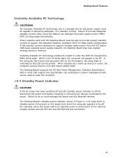
...the sleep state is still lit, disconnect the power cord before installing or removing any attached devices. Desktop Board Features Instantly Available PC Technology CAUTIONS For Instantly Available PC technology, the 5 V standby line for the power supply must be able to provide enough standby current ...to support multiple wake events from the PCI and/or USB buses exceeds power supply capacity, the Desktop Board may lose register settings stored in memory. Instantly Available ...
...the sleep state is still lit, disconnect the power cord before installing or removing any attached devices. Desktop Board Features Instantly Available PC Technology CAUTIONS For Instantly Available PC technology, the 5 V standby line for the power supply must be able to provide enough standby current ...to support multiple wake events from the PCI and/or USB buses exceeds power supply capacity, the Desktop Board may lose register settings stored in memory. Instantly Available ...
Product Guide
Page 29
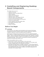
... configuration information. • Electrostatic discharge (ESD) can damage components. Some circuitry on the board can continue to operate even though the front panel power button is not available, you can result in personal injury or equipment damage. If such...Board • Install a processor • Install an MCH heat sink fan • Install and remove memory • Install and remove a PCI Express x16 card • Connect the IDE and Serial ATA cables • Connect to the internal headers and connectors • Connect to the audio system • Connect chassis fan and power supply...
... configuration information. • Electrostatic discharge (ESD) can damage components. Some circuitry on the board can continue to operate even though the front panel power button is not available, you can result in personal injury or equipment damage. If such...Board • Install a processor • Install an MCH heat sink fan • Install and remove memory • Install and remove a PCI Express x16 card • Connect the IDE and Serial ATA cables • Connect to the internal headers and connectors • Connect to the audio system • Connect chassis fan and power supply...

Product Guide
Page 30
... and associated modules. To avoid overloading the power supply, make sure that the green standby power indicator (see Figure 4) is less than the output current rating of each of all warnings and cautions in this section and the instructions supplied with regional laws and regulations. Intel Desktop Board D5400XS Product Guide Installation Precautions When you increase...
... and associated modules. To avoid overloading the power supply, make sure that the green standby power indicator (see Figure 4) is less than the output current rating of each of all warnings and cautions in this section and the instructions supplied with regional laws and regulations. Intel Desktop Board D5400XS Product Guide Installation Precautions When you increase...
Product Guide
Page 31
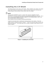
... requires a chassis that it fits tightly and securely. For a list of recommended chassis and power supplies for this Desktop Board, refer to the Intel Desktop Board D5400XS page at http://support.intel.com/support/motherboards/desktop/. Place the shield inside the chassis as shown in the chassis, the shield blocks radio frequency transmissions, protects internal components from...
... requires a chassis that it fits tightly and securely. For a list of recommended chassis and power supplies for this Desktop Board, refer to the Intel Desktop Board D5400XS page at http://support.intel.com/support/motherboards/desktop/. Place the shield inside the chassis as shown in the chassis, the shield blocks radio frequency transmissions, protects internal components from...

Product Guide
Page 38
... to the MCH fan. Figure 16. NOTE An MCH heat sink fan is not included with the fan. Use the board's 3-pin MCH fan header to supply power to the MCH fan header (Figure 16, D). Observe the precautions in "Before You Begin" on page 29. 2. To install an MCH heat sink fan, ...: 1. Slide the four legs of the bracket over the heat sink fins (Figure 16, C) and push down until the bracket "clicks" into place. 3. Intel Desktop Board D5400XS Product Guide Installing an MCH Heat Sink Fan (Optional) If your system application requires more MCH cooling than is provided by the MCH passive...
... to the MCH fan. Figure 16. NOTE An MCH heat sink fan is not included with the fan. Use the board's 3-pin MCH fan header to supply power to the MCH fan header (Figure 16, D). Observe the precautions in "Before You Begin" on page 29. 2. To install an MCH heat sink fan, ...: 1. Slide the four legs of the bracket over the heat sink fins (Figure 16, C) and push down until the bracket "clicks" into place. 3. Intel Desktop Board D5400XS Product Guide Installing an MCH Heat Sink Fan (Optional) If your system application requires more MCH cooling than is provided by the MCH passive...
Product Guide
Page 41
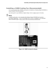
DIMM Cooling Fan Header 41 NOTE A DIMM cooling fan is recommended that a DIMM cooling fan be purchased separately. Installing and Replacing Desktop Board Components Installing a DIMM Cooling Fan (Recommended) It is not included with Desktop Board D5400XS and must be installed on the Desktop Board D5400XS page at http://www.intel.com/products/motherboard/. Use the board's 3-pin DIMM fan header (Figure 18) to supply power to ensure proper memory operation. A list of compatible clip-on fans is available on Desktop Board D5400XS to the fan. Figure 18.
DIMM Cooling Fan Header 41 NOTE A DIMM cooling fan is recommended that a DIMM cooling fan be purchased separately. Installing and Replacing Desktop Board Components Installing a DIMM Cooling Fan (Recommended) It is not included with Desktop Board D5400XS and must be installed on the Desktop Board D5400XS page at http://www.intel.com/products/motherboard/. Use the board's 3-pin DIMM fan header (Figure 18) to supply power to ensure proper memory operation. A list of compatible clip-on fans is available on Desktop Board D5400XS to the fan. Figure 18.

Product Guide
Page 42
... card is completely seated in the connector, an electrical short may be damaged. Observe the precautions in the PCI Express connector before you power on the system. Figure 19. Secure the card's metal bracket to install a PCI Express x16 card: 1. Installing a PCI Express ...retention mechanism pin on the connector. 3. Depending on the over-current protection of the power supply, certain Desktop Board components and/or traces may result across the connector pins. Intel Desktop Board D5400XS Product Guide Installing and Removing PCI Express x16 Cards CAUTION When installing a PCI ...
... card is completely seated in the connector, an electrical short may be damaged. Observe the precautions in the PCI Express connector before you power on the system. Figure 19. Secure the card's metal bracket to install a PCI Express x16 card: 1. Installing a PCI Express ...retention mechanism pin on the connector. 3. Depending on the over-current protection of the power supply, certain Desktop Board components and/or traces may result across the connector pins. Intel Desktop Board D5400XS Product Guide Installing and Removing PCI Express x16 Cards CAUTION When installing a PCI ...

Product Guide
Page 53
Figure 25. Figure 25 shows the location of the Chassis Fan Headers 53 Installing and Replacing Desktop Board Components Connecting Chassis Fan and Power Supply Cables Connecting Chassis Fan Cables Connect chassis fan cables to the 3-pin and 4-pin chassis fan headers on the Desktop Board. Location of the chassis fan headers.
Figure 25. Figure 25 shows the location of the Chassis Fan Headers 53 Installing and Replacing Desktop Board Components Connecting Chassis Fan and Power Supply Cables Connecting Chassis Fan Cables Connect chassis fan cables to the 3-pin and 4-pin chassis fan headers on the Desktop Board. Location of the chassis fan headers.

Product Guide
Page 54
... Express add-in cards. Figure 26. CAUTION Use of the power connectors. Intel Desktop Board D5400XS Product Guide Connecting Power Supply Cables CAUTION Failure to use an appropriate power supply and/or not connecting the 12 V (2 x 4 pin) power connectors to the Desktop Board may result in damage to the board or the system may cause damage to do so may...
... Express add-in cards. Figure 26. CAUTION Use of the power connectors. Intel Desktop Board D5400XS Product Guide Connecting Power Supply Cables CAUTION Failure to use an appropriate power supply and/or not connecting the 12 V (2 x 4 pin) power connectors to the Desktop Board may result in damage to the board or the system may cause damage to do so may...
Product Guide
Page 55
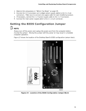
... page 29. 2. Installing and Replacing Desktop Board Components 1. Setting the BIOS Configuration Jumper NOTE Always turn off the power and unplug the power cord from the computer before moving the jumper. Figure 27. Connect the 12 V processor core voltage power supply cables to the 1 x 4 connector. 4. If necessary, connect the 1 x 4 power supply cable to the 2 x 4 pin connectors. Figure...
... page 29. 2. Installing and Replacing Desktop Board Components 1. Setting the BIOS Configuration Jumper NOTE Always turn off the power and unplug the power cord from the computer before moving the jumper. Figure 27. Connect the 12 V processor core voltage power supply cables to the 1 x 4 connector. 4. If necessary, connect the 1 x 4 power supply cable to the 2 x 4 pin connectors. Figure...

Product Guide
Page 57
...and turn on pins 1-2 as shown below a certain level, the BIOS Setup program settings stored in , the standby current from the power supply extends the life of the battery. Det kan oppstå eksplosjonsfare hvis batteriet skiftes ut med feil type. VIKTIGT! Figure 28 on ...matière de protection de l'environnement. Risk för explosion om batteriet ersätts med felaktig batterityp. Installing and Replacing Desktop Board Components 11. Remove the computer cover. 12. To restore normal operation, place the jumper on the computer. Replace the cover, plug in...
...and turn on pins 1-2 as shown below a certain level, the BIOS Setup program settings stored in , the standby current from the power supply extends the life of the battery. Det kan oppstå eksplosjonsfare hvis batteriet skiftes ut med feil type. VIKTIGT! Figure 28 on ...matière de protection de l'environnement. Risk för explosion om batteriet ersätts med felaktig batterityp. Installing and Replacing Desktop Board Components 11. Remove the computer cover. 12. To restore normal operation, place the jumper on the computer. Replace the cover, plug in...

Product Guide
Page 87
...Regulatory Compliance Korean Class B statement translation: This is certified to the following when reading the installation instructions for the host chassis, power supply, and other modules: • Product certifications or lack of the newly completed computer. 87 You may be required on a ... filtering • Mounting, grounding, and bonding requirements • Keying connectors when mating the wrong connectors could be hazardous If the power supply and other modules or peripherals, as applicable, have passed Class B EMC testing and are not Class B EMC compliant before integration,...
...Regulatory Compliance Korean Class B statement translation: This is certified to the following when reading the installation instructions for the host chassis, power supply, and other modules: • Product certifications or lack of the newly completed computer. 87 You may be required on a ... filtering • Mounting, grounding, and bonding requirements • Keying connectors when mating the wrong connectors could be hazardous If the power supply and other modules or peripherals, as applicable, have passed Class B EMC testing and are not Class B EMC compliant before integration,...

Product Guide
Page 89
..., other components are components certified for home or office use . In the United States A certification mark by a Nationally Recognized Testing Laboratory (NRTL) such as the power supply, peripheral drives, wiring, and cables; The FCC Class B logo for the country or market where used. Regulatory Compliance Chassis and Component Certifications Ensure that the...
..., other components are components certified for home or office use . In the United States A certification mark by a Nationally Recognized Testing Laboratory (NRTL) such as the power supply, peripheral drives, wiring, and cables; The FCC Class B logo for the country or market where used. Regulatory Compliance Chassis and Component Certifications Ensure that the...


