
User Guide
Page 2
... Reserved ii Intel® Entry Server Chassis SC5299-E UP/DP/WS/BRP User Guide Intel, Intel Pentium, and Intel Xeon are not designed, intended or authorized for use in any medical, life saving, or life sustaining applications or for any other countries. * Other names and brands may be held responsible if components fail or the server board does...
... Reserved ii Intel® Entry Server Chassis SC5299-E UP/DP/WS/BRP User Guide Intel, Intel Pentium, and Intel Xeon are not designed, intended or authorized for use in any medical, life saving, or life sustaining applications or for any other countries. * Other names and brands may be held responsible if components fail or the server board does...

User Guide
Page 3
... mises en garde indiquées dans ce document avant de suivre toute instruction. Vea Intel Server Boards and Server Chassis Safety Information en el Intel® Server Deployment Toolkit CD y/o en http://support.intel.com/ support/motherboards/server/sb/cs-010770.htm Intel® Entry Server Chassis SC5299-E UP/DP/WS/BRP User Guide iii Beachten Sie hierzu auch die Sicherheitshinweise...
... mises en garde indiquées dans ce document avant de suivre toute instruction. Vea Intel Server Boards and Server Chassis Safety Information en el Intel® Server Deployment Toolkit CD y/o en http://support.intel.com/ support/motherboards/server/sb/cs-010770.htm Intel® Entry Server Chassis SC5299-E UP/DP/WS/BRP User Guide iii Beachten Sie hierzu auch die Sicherheitshinweise...
User Guide
Page 5
... components. This manual is compatible with the following Intel® Server Boards: • Intel® Server Board S5000XVN • Intel® Server Board S5000VSA • Intel® Server Board S5000PSL • Intel® Server Board S5000XSL • Intel® Server Board S3000AH • Intel® Server Board S3200SHV • Intel® Server Board S3210SHLC • Intel® Server Board S3210SHLX Your Intel® Entry Server Chassis SC5299-E ships with the following items: Intel® Entry Server Chassis SC5299-E UP/DP/WS/BRP User Guide...
... components. This manual is compatible with the following Intel® Server Boards: • Intel® Server Board S5000XVN • Intel® Server Board S5000VSA • Intel® Server Board S5000PSL • Intel® Server Board S5000XSL • Intel® Server Board S3000AH • Intel® Server Board S3200SHV • Intel® Server Board S3210SHLC • Intel® Server Board S3210SHLX Your Intel® Entry Server Chassis SC5299-E ships with the following items: Intel® Entry Server Chassis SC5299-E UP/DP/WS/BRP User Guide...
User Guide
Page 6
... Document or Software Intel® Entry Server Chassis SC5299-E Technical Product Specification Intel® Entry Server Chassis SC5299-E Quick Start User's Guide in the hardware kit • Fifteen 6-32 screws for Intel® products, see http://support.intel.com/support/motherboards/server/chassis/sc5299e/compat.... vi Intel® Entry Server Chassis SC5299-E UP/DP/WS/BRP User Guide For information about the accessories that can be used with this server chassis, use the following accessory items for your server board, and for ordering information for mounting the server board to ...
... Document or Software Intel® Entry Server Chassis SC5299-E Technical Product Specification Intel® Entry Server Chassis SC5299-E Quick Start User's Guide in the hardware kit • Fifteen 6-32 screws for Intel® products, see http://support.intel.com/support/motherboards/server/chassis/sc5299e/compat.... vi Intel® Entry Server Chassis SC5299-E UP/DP/WS/BRP User Guide For information about the accessories that can be used with this server chassis, use the following accessory items for your server board, and for ordering information for mounting the server board to ...
User Guide
Page 9
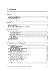
...iii Warnings ...iv Preface ...v About this Manual ...v Manual Organization ...v Product Contents, Order Options, and Accessories v Additional Information and Software vi Server Chassis Features 1 Component Identification ...3 Front View Components 3 Internal Components ...5 Back Panel Components 7 Front Panel ...8 Peripheral Devices ...9 Hard Disk ... Duct 19 Installing the Processor Air Duct 20 Installing or Removing a Server Board 20 Installing and Removing a Fixed Hard Drive 26 Installing a Fixed Hard Drive 26 Intel® Entry Server Chassis SC5299-E UP/DP/WS/BRP User Guide ix
...iii Warnings ...iv Preface ...v About this Manual ...v Manual Organization ...v Product Contents, Order Options, and Accessories v Additional Information and Software vi Server Chassis Features 1 Component Identification ...3 Front View Components 3 Internal Components ...5 Back Panel Components 7 Front Panel ...8 Peripheral Devices ...9 Hard Disk ... Duct 19 Installing the Processor Air Duct 20 Installing or Removing a Server Board 20 Installing and Removing a Fixed Hard Drive 26 Installing a Fixed Hard Drive 26 Intel® Entry Server Chassis SC5299-E UP/DP/WS/BRP User Guide ix
User Guide
Page 19
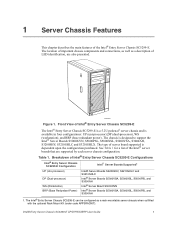
... SC5299-E can be configured as a description of Intel® Entry Server Chassis SC5299-E Configurations Intel® Entry Server Chassis SC5299-E Configuration Intel® Server Boards Supported1 UP (Uni-processor) DP (Dual-processor) WS (Workstation) BRP (Base Redundant Power) Intel® Server Boards S3200SHV, S3210SHLC and S3210SHLX Intel® Server Boards S5000VSA, S5000XSL, S5000PSL and S3000AH Intel® Server Board S5000XVN Intel® Server Boards S5000VSA, S5000XSL, S5000PSL and S3000AH 1. The chassis is...
... SC5299-E can be configured as a description of Intel® Entry Server Chassis SC5299-E Configurations Intel® Entry Server Chassis SC5299-E Configuration Intel® Server Boards Supported1 UP (Uni-processor) DP (Dual-processor) WS (Workstation) BRP (Base Redundant Power) Intel® Server Boards S3200SHV, S3210SHLC and S3210SHLX Intel® Server Boards S5000VSA, S5000XSL, S5000PSL and S3000AH Intel® Server Board S5000XVN Intel® Server Boards S5000VSA, S5000XSL, S5000PSL and S3000AH 1. The chassis is...

User Guide
Page 20
...PFC tool-less fixed power supply • DP - ships with a 650-W PFC redundant power supply module in hard drives. For updated server board support, go to create a 1+1 configuration. • One 120-mm system fan • One power supply fan1 • Processor ...supply is dependent on configuration of the Intel® Entry Server Chassis SC5299-E. An additional module can be purchased as an accessory to http://support.intel.com/support/motherboards/server/ chassis/sc5299-e/. Table 2. ships with WS chassis configuration 2 Intel® Entry Server Chassis SC5299-E UP/DP/WS/BRP ...
...PFC tool-less fixed power supply • DP - ships with a 650-W PFC redundant power supply module in hard drives. For updated server board support, go to create a 1+1 configuration. • One 120-mm system fan • One power supply fan1 • Processor ...supply is dependent on configuration of the Intel® Entry Server Chassis SC5299-E. An additional module can be purchased as an accessory to http://support.intel.com/support/motherboards/server/ chassis/sc5299-e/. Table 2. ships with WS chassis configuration 2 Intel® Entry Server Chassis SC5299-E UP/DP/WS/BRP ...
User Guide
Page 25
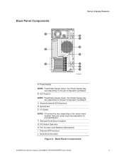
...Intel® Entry Server Chassis SC5299-E UP/DP/WS/BRP User Guide 7 Your Power Supply may vary depending on chassis configuration purchased. Alternate Serial B port knockout G. Serial B port knockout Figure 6. Your Power Supply may vary depending on the server board installed. System Fan E. See your server board... documentation for port identification F. PCI Add-in Card slots H. Back Panel Components Server Chassis Features A B C D E F G H I ....
...Intel® Entry Server Chassis SC5299-E UP/DP/WS/BRP User Guide 7 Your Power Supply may vary depending on chassis configuration purchased. Alternate Serial B port knockout G. Serial B port knockout Figure 6. Your Power Supply may vary depending on the server board installed. System Fan E. See your server board... documentation for port identification F. PCI Add-in Card slots H. Back Panel Components Server Chassis Features A B C D E F G H I ....

User Guide
Page 26
...S1 Sleep state. NIC 1 Activity LED Continuous green light indicates a link between system and network. Front Panel Components 8 Intel® Entry Server Chassis SC5299-E UP/DP/WS/BRP User Guide Power/Sleep LED Powers the system off / or the system is in ...light indicates a hard drive fault. NOTES: 1. No light indicates the NIC is off or on server board integrated. Status LED Solid green indicates system ready (not supported by all server boards). Solid amber indicates a critical temperature or voltage fault, or a missing CPU/terminator. H. No ...
...S1 Sleep state. NIC 1 Activity LED Continuous green light indicates a link between system and network. Front Panel Components 8 Intel® Entry Server Chassis SC5299-E UP/DP/WS/BRP User Guide Power/Sleep LED Powers the system off / or the system is in ...light indicates a hard drive fault. NOTES: 1. No light indicates the NIC is off or on server board integrated. Status LED Solid green indicates system ready (not supported by all server boards). Solid amber indicates a critical temperature or voltage fault, or a missing CPU/terminator. H. No ...

User Guide
Page 31
...Left Side Cover The Intel® Entry Server Chassis SC5299-E must be needed to ensure proper cooling. For instructions on replacing components on the server board, such as it would be operated with the left side cover installed to prevent the chassis from sliding on your server product, review the... the front of the platform. You will need to remove the left side cover, power down the server and unplug all peripheral devices connected to ensure proper cooling. Intel® Entry Server Chassis SC5299-E UP/DP/WS/BRP User Guide 13 Tools and Supplies Needed • Phillips* (cross...
...Left Side Cover The Intel® Entry Server Chassis SC5299-E must be needed to ensure proper cooling. For instructions on replacing components on the server board, such as it would be operated with the left side cover installed to prevent the chassis from sliding on your server product, review the... the front of the platform. You will need to remove the left side cover, power down the server and unplug all peripheral devices connected to ensure proper cooling. Intel® Entry Server Chassis SC5299-E UP/DP/WS/BRP User Guide 13 Tools and Supplies Needed • Phillips* (cross...

User Guide
Page 37
...is built into the left side cover. Loosen the two mounting screws and remove the processor air duct. TP01136 Figure 16. Intel® Entry Server Chassis SC5299-E UP/DP/WS/BRP User Guide 19 Hardware Installations and Upgrades Removing and Installing the Processor Air Duct Warning: ... applicable to the UP configuration of the Intel® Entry Server Chassis SC5299-E. Removal of the left side cover. The processor air duct on processor installation and removal. Remove the left side cover will need them to your server board User Guide for proper airflow within the ...
...is built into the left side cover. Loosen the two mounting screws and remove the processor air duct. TP01136 Figure 16. Intel® Entry Server Chassis SC5299-E UP/DP/WS/BRP User Guide 19 Hardware Installations and Upgrades Removing and Installing the Processor Air Duct Warning: ... applicable to the UP configuration of the Intel® Entry Server Chassis SC5299-E. Removal of the left side cover. The processor air duct on processor installation and removal. Remove the left side cover will need them to your server board User Guide for proper airflow within the ...

User Guide
Page 38
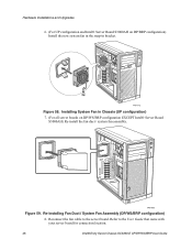
... and Upgrades Installing the Processor Air Duct Note: The following procedure is not applicable to the DP/BRP configuration of the Intel® Entry Server Chassis SC5299-E if you have an Intel® Server Board S3000AH installed. Note: The following procedure is required for proper airflow within the chassis. 1. Power up with two mounting screws. To...
... and Upgrades Installing the Processor Air Duct Note: The following procedure is not applicable to the DP/BRP configuration of the Intel® Entry Server Chassis SC5299-E if you have an Intel® Server Board S3000AH installed. Note: The following procedure is required for proper airflow within the chassis. 1. Power up with two mounting screws. To...

User Guide
Page 41
... guide into chassis until right-side blue tabs snap into Chassis Intel® Entry Server Chassis SC5299-E UP/DP/WS/BRP User Guide 23 Re-installing PCI Card Guide into place (see letter "B"). A B TP01735 Figure 21. If installing a server board, refer to your Intel® Server Board User's Guide and/or Quick Start User's Guide for installation instructions...
... guide into chassis until right-side blue tabs snap into Chassis Intel® Entry Server Chassis SC5299-E UP/DP/WS/BRP User Guide 23 Re-installing PCI Card Guide into place (see letter "B"). A B TP01735 Figure 21. If installing a server board, refer to your Intel® Server Board User's Guide and/or Quick Start User's Guide for installation instructions...

User Guide
Page 56
... the Removing PCI Add-in Boards The following instructions describe how to determine PCI add-in the Intel® Entry Server Chassis SC5299-E. See your server board documentation to install and remove a PCI add-in board in board compatibility. Installing PCI Add-in boards. 1. If not replacing the...". 2. Reconnect all peripheral devices and the AC power cable. 38 Intel® Entry Server Chassis SC5299-E UP/DP/WS/BRP User Guide Observe the safety and ESD precautions listed in boards can be extremely sensitive to install an operating system before installing any surface...
... the Removing PCI Add-in Boards The following instructions describe how to determine PCI add-in the Intel® Entry Server Chassis SC5299-E. See your server board documentation to install and remove a PCI add-in board in board compatibility. Installing PCI Add-in boards. 1. If not replacing the...". 2. Reconnect all peripheral devices and the AC power cable. 38 Intel® Entry Server Chassis SC5299-E UP/DP/WS/BRP User Guide Observe the safety and ESD precautions listed in boards can be extremely sensitive to install an operating system before installing any surface...

User Guide
Page 58
... figure). For instructions, see "Installing the Left Side Cover". 11. Power up on the server board (see letter "B"). Close the back panel PCI Add-in Appendix A, "Safety Information". 2. For instructions, see "Removing the Left Side Cover". 40 Intel® Entry Server Chassis SC5299-E UP/DP/WS/BRP User Guide Hardware Installations and Upgrades 7. Hold the...
... figure). For instructions, see "Installing the Left Side Cover". 11. Power up on the server board (see letter "B"). Close the back panel PCI Add-in Appendix A, "Safety Information". 2. For instructions, see "Removing the Left Side Cover". 40 Intel® Entry Server Chassis SC5299-E UP/DP/WS/BRP User Guide Hardware Installations and Upgrades 7. Hold the...

User Guide
Page 59
... and Upgrades 4. Opening PCI Add-in Board Intel® Entry Server Chassis SC5299-E UP/DP/WS/BRP User Guide 41 Removing PCI Add-in Card Retention Device (DP/WS/BRP configuration shown) 5. Firmly grab the PCI add-in board by pressing open from the expansion slot on the server board (see letter "B"). Close the back panel...cables that may be attached to the PCI add-in an anti-static protective wrapper. BB A TP01724 Figure 47. Place the removed add-in board in board that needs to be removed. 6. TP02049 Figure 46. Open the back panel PCI Add-in the following figure).
... and Upgrades 4. Opening PCI Add-in Board Intel® Entry Server Chassis SC5299-E UP/DP/WS/BRP User Guide 41 Removing PCI Add-in Card Retention Device (DP/WS/BRP configuration shown) 5. Firmly grab the PCI add-in board by pressing open from the expansion slot on the server board (see letter "B"). Close the back panel...cables that may be attached to the PCI add-in an anti-static protective wrapper. BB A TP01724 Figure 47. Place the removed add-in board in board that needs to be removed. 6. TP02049 Figure 46. Open the back panel PCI Add-in the following figure).

User Guide
Page 65
... Assembly (DP/WS/BRP configuration) 5. (For UP configuration and Intel® Server Board S3000AH on DP/WS/BRP configuration EXCEPT Intel® Server Board S3000AH) Remove the fan duct /system fan assembly. B A TP00884 Figure 57. AF000284 Figure 56. Remove the system fan from Chassis (UP Configuration) Intel® Entry Server Chassis SC5299-E UP/DP/WS/BRP User Guide 47...
... Assembly (DP/WS/BRP configuration) 5. (For UP configuration and Intel® Server Board S3000AH on DP/WS/BRP configuration EXCEPT Intel® Server Board S3000AH) Remove the fan duct /system fan assembly. B A TP00884 Figure 57. AF000284 Figure 56. Remove the system fan from Chassis (UP Configuration) Intel® Entry Server Chassis SC5299-E UP/DP/WS/BRP User Guide 47...
User Guide
Page 66
... in Chassis (UP configuration) 7. (For all server boards on DP/BRP configuration) Install the new system fan in the snap-in bracket. Refer to the server board. TP01853 Figure 59. Reconnect the fan cable to the User Guide that came with your server board for connection location. 48 Intel® Entry Server Chassis SC5299-E UP/DP/WS/BRP User...
... in Chassis (UP configuration) 7. (For all server boards on DP/BRP configuration) Install the new system fan in the snap-in bracket. Refer to the server board. TP01853 Figure 59. Reconnect the fan cable to the User Guide that came with your server board for connection location. 48 Intel® Entry Server Chassis SC5299-E UP/DP/WS/BRP User...
User Guide
Page 67
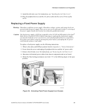
... removing or replacing the fixed power supply, you must first take the server out of service, turn off all internal power cables from chassis components and server board. 5. For instructions, see "Installing the Left Side Cover". 10. Install the left side cover. ... 60. Observe the safety and ESD precautions listed in the following instructions: 1. Remove the left side cover. servicing of the Intel® Entry Server Chassis SC5299-E. Unlocking Fixed Power Supply from the system or wall outlet. Hardware Installations and Upgrades 9. Plug all peripheral devices and...
... removing or replacing the fixed power supply, you must first take the server out of service, turn off all internal power cables from chassis components and server board. 5. For instructions, see "Installing the Left Side Cover". 10. Install the left side cover. ... 60. Observe the safety and ESD precautions listed in the following instructions: 1. Remove the left side cover. servicing of the Intel® Entry Server Chassis SC5299-E. Unlocking Fixed Power Supply from the system or wall outlet. Hardware Installations and Upgrades 9. Plug all peripheral devices and...

User Guide
Page 69
...the Left Side Cover". 14. Route the P3 and P4 cables to 8-pin white connector on the server board. Note: For Intel® Server Board S3000AH with your Intel® server board for appropriate power connections. 10. For instructions, see letter "A" in . Hardware Installations and Upgrades 8....Power up the server. Rotate the blue locking mechanism to reach the 8-pin white CPU connector on server board, re-install secondary side cover. 13. Route the P5 cable to installed devices. Locking Fixed Power Supply into Chassis 9. Intel® Entry Server Chassis SC5299-E ...
...the Left Side Cover". 14. Route the P3 and P4 cables to 8-pin white connector on the server board. Note: For Intel® Server Board S3000AH with your Intel® server board for appropriate power connections. 10. For instructions, see letter "A" in . Hardware Installations and Upgrades 8....Power up the server. Rotate the blue locking mechanism to reach the 8-pin white CPU connector on server board, re-install secondary side cover. 13. Route the P5 cable to installed devices. Locking Fixed Power Supply into Chassis 9. Intel® Entry Server Chassis SC5299-E ...


