
User Guide
Page 3
... information, and step-by-step instructions for adding and replacing components in troubleshooting the Intel® Compute Module MFS5520VI. Chapter 2 provides instructions for troubleshooting, upgrading, and repairing compute modules. Manual Organization Chapter 1 provides a brief overview of this manual,see http:// www.intel.com/support/motherboards/server/MFS5520VI/. Chapter 3 provides information regarding the BIOS Setup Utility and how to access and use...
... information, and step-by-step instructions for adding and replacing components in troubleshooting the Intel® Compute Module MFS5520VI. Chapter 2 provides instructions for troubleshooting, upgrading, and repairing compute modules. Manual Organization Chapter 1 provides a brief overview of this manual,see http:// www.intel.com/support/motherboards/server/MFS5520VI/. Chapter 3 provides information regarding the BIOS Setup Utility and how to access and use...
User Guide
Page 7
Contents Preface ...iii About this Manual ...iii Manual Organization ...iii Safety Information ...v Important Safety Instructions v Wichtige Sicherheitshinweise v Consignes de sécurité ...v Instrucciones de seguridad importantes v Warnings...vi Compute Module Features 1 Feature Overview ...3 Connector and Component Locations 4 ... Needed ...13 Installation Guidelines ...13 Removing and Installing an Intel® Compute Module MFS5520VI 13 Removing a Compute Module from the Chassis 13 Installing a Compute Module into the Chassis 14 Removing or Installing the Top Cover 14...
Contents Preface ...iii About this Manual ...iii Manual Organization ...iii Safety Information ...v Important Safety Instructions v Wichtige Sicherheitshinweise v Consignes de sécurité ...v Instrucciones de seguridad importantes v Warnings...vi Compute Module Features 1 Feature Overview ...3 Connector and Component Locations 4 ... Needed ...13 Installation Guidelines ...13 Removing and Installing an Intel® Compute Module MFS5520VI 13 Removing a Compute Module from the Chassis 13 Installing a Compute Module into the Chassis 14 Removing or Installing the Top Cover 14...

User Guide
Page 27
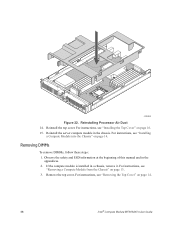
... at the beginning of this manual and in the appendices. 2. Removing and Installing an Intel® Compute Module MFS5520VI Removing a Compute Module from the Chassis To remove a compute module from the chassis. Tools and...compute module from the chassis, follow these steps: 1. For a complete list of installation or removal steps, see the instructions included with your server product, review the safety and ESD information at the beginning of the following color coding on a component indicates a touch point, where you must first shut down . 3. Intel® Compute Module MFS5520VI...
... at the beginning of this manual and in the appendices. 2. Removing and Installing an Intel® Compute Module MFS5520VI Removing a Compute Module from the Chassis To remove a compute module from the chassis. Tools and...compute module from the chassis, follow these steps: 1. For a complete list of installation or removal steps, see the instructions included with your server product, review the safety and ESD information at the beginning of the following color coding on a component indicates a touch point, where you must first shut down . 3. Intel® Compute Module MFS5520VI...

User Guide
Page 28
.... 2. This step is a required component of this manual and in the appendices. 2. Observe the safety and ESD information at the beginning of the compute module; Make sure the retention levers on a flat, non-conductive surface, with the cover side up. 14 Intel® Compute Module MFS5520VI User Guide Insert the compute module into a chassis without a top cover installed. 3. Close...
.... 2. This step is a required component of this manual and in the appendices. 2. Observe the safety and ESD information at the beginning of the compute module; Make sure the retention levers on a flat, non-conductive surface, with the cover side up. 14 Intel® Compute Module MFS5520VI User Guide Insert the compute module into a chassis without a top cover installed. 3. Close...

User Guide
Page 30
..., check that all components are inside the compute module. 3. Slide the top cover forward to the closed position until the retention latch fully engages (see letter "A" in the appendices. 2. Observe the safety and ESD information at the beginning of this manual and in Figure 7). A B 1 I/O... 2 1 2 ID Figure 7. Installing the Top Cover To install the top cover, follow these steps: 1. Installing Top Cover AF003089 16 Intel® Compute Module MFS5520VI User Guide Place the top cover on the compute module so that no ...
..., check that all components are inside the compute module. 3. Slide the top cover forward to the closed position until the retention latch fully engages (see letter "A" in the appendices. 2. Observe the safety and ESD information at the beginning of this manual and in Figure 7). A B 1 I/O... 2 1 2 ID Figure 7. Installing the Top Cover To install the top cover, follow these steps: 1. Installing Top Cover AF003089 16 Intel® Compute Module MFS5520VI User Guide Place the top cover on the compute module so that no ...

User Guide
Page 31
...beginning of this manual and in damage to remove the cover could result in the appendices. failure to the compute module. Remove the top cover. Removing Components 2. For instructions, see "Removing a Compute Module from the Chassis" on page 14. If the compute module is installed ...the processor by doing the following: (1) Touch the metal chassis before touching the processor or compute module. Keep part of your body in a chassis, remove it. Intel® Compute Module MFS5520VI User Guide 17 Installing or Replacing a Processor Caution: Processor must be removed for proper ...
...beginning of this manual and in damage to remove the cover could result in the appendices. failure to the compute module. Remove the top cover. Removing Components 2. For instructions, see "Removing a Compute Module from the Chassis" on page 14. If the compute module is installed ...the processor by doing the following: (1) Touch the metal chassis before touching the processor or compute module. Keep part of your body in a chassis, remove it. Intel® Compute Module MFS5520VI User Guide 17 Installing or Replacing a Processor Caution: Processor must be removed for proper ...

User Guide
Page 39
...manual and in a chassis, remove it. Remove the top cover. For instructions, see Figure 18). 1 I/O 2 1 2 ID Figure 18. Remove the processor air duct (see "Removing the Top Cover" on page 13. 3. For instructions, see "Removing a Compute Module from the Chassis" on page 14. 4. Removing Processor Air Duct AF003080 Intel® Compute Module MFS5520VI... User Guide 25 Removing Components 2. If the compute module is installed in the appendices...
...manual and in a chassis, remove it. Remove the top cover. For instructions, see Figure 18). 1 I/O 2 1 2 ID Figure 18. Remove the processor air duct (see "Removing the Top Cover" on page 13. 3. For instructions, see "Removing a Compute Module from the Chassis" on page 14. 4. Removing Processor Air Duct AF003080 Intel® Compute Module MFS5520VI... User Guide 25 Removing Components 2. If the compute module is installed in the appendices...

User Guide
Page 50
... in Figure 31 - For instructions, see letter "B" in the DIMM socket (see "Removing a Compute Module from the Chassis" on page 14. 4. Removing Processor Air Duct 5. the arrow is installed in Figure 31). 36 Intel® Compute Module MFS5520VI User Guide If the compute module is pointing to the open position (see letter "C" in a chassis, remove it. Holding the... the DIMM by the edges, remove it from the package. 7. Position the DIMM above the socket. Align the notch on the top edge of this manual and in Figure 31). 8.
... in Figure 31 - For instructions, see letter "B" in the DIMM socket (see "Removing a Compute Module from the Chassis" on page 14. 4. Removing Processor Air Duct 5. the arrow is installed in Figure 31). 36 Intel® Compute Module MFS5520VI User Guide If the compute module is pointing to the open position (see letter "C" in a chassis, remove it. Holding the... the DIMM by the edges, remove it from the package. 7. Position the DIMM above the socket. Align the notch on the top edge of this manual and in Figure 31). 8.
User Guide
Page 52
... this manual and in a chassis, remove it. If the compute module is installed in the appendices. 2. Remove the top cover. 1 I/O 2 1 2 ID AF003080 Figure 32. For instructions, see "Installing a Compute Module into the Chassis" on page 13. 3. For instructions, see "Removing a Compute Module from ...Reinstall the top cover. Removing DIMMs To remove DIMMs, follow these steps: 1. Reinstall the server compute module in the chassis. For instructions, see "Installing the Top Cover" on page 14. 38 Intel® Compute Module MFS5520VI User Guide Reinstalling Processor Air Duct 14.
... this manual and in a chassis, remove it. If the compute module is installed in the appendices. 2. Remove the top cover. 1 I/O 2 1 2 ID AF003080 Figure 32. For instructions, see "Installing a Compute Module into the Chassis" on page 13. 3. For instructions, see "Removing a Compute Module from ...Reinstall the top cover. Removing DIMMs To remove DIMMs, follow these steps: 1. Reinstall the server compute module in the chassis. For instructions, see "Installing the Top Cover" on page 14. 38 Intel® Compute Module MFS5520VI User Guide Reinstalling Processor Air Duct 14.

User Guide
Page 56
.... 2. Locate the mezzanine card connectors on page 14. 4. For instructions, see "Removing the Top Cover" on the server board. 42 Intel® Compute Module MFS5520VI User Guide Observe the safety and ESD information at the beginning of this manual and in a chassis, remove it from the packaging. 5. Remove the top cover. Holding the mezzanine card by...
.... 2. Locate the mezzanine card connectors on page 14. 4. For instructions, see "Removing the Top Cover" on the server board. 42 Intel® Compute Module MFS5520VI User Guide Observe the safety and ESD information at the beginning of this manual and in a chassis, remove it from the packaging. 5. Remove the top cover. Holding the mezzanine card by...

User Guide
Page 60
... instructions, see Figure 39). 1 I/O 2 1 2 ID Figure 39. For instructions, see "Removing a Compute Module from Mezzanine Card AF003091 46 Intel® Compute Module MFS5520VI User Guide Using a Phillips* screwdriver, remove the four screws securing the mezzanine card to the standoffs (see...4. Remove the top cover. Removing a Mezzanine Card To remove a mezzanine card, follow these steps: 1. If the compute module is installed in the appendices. 2. Observe the safety and ESD information at the beginning of this manual and in a chassis, remove it. Locate the mezzanine card. 5.
... instructions, see Figure 39). 1 I/O 2 1 2 ID Figure 39. For instructions, see "Removing a Compute Module from Mezzanine Card AF003091 46 Intel® Compute Module MFS5520VI User Guide Using a Phillips* screwdriver, remove the four screws securing the mezzanine card to the standoffs (see...4. Remove the top cover. Removing a Mezzanine Card To remove a mezzanine card, follow these steps: 1. If the compute module is installed in the appendices. 2. Observe the safety and ESD information at the beginning of this manual and in a chassis, remove it. Locate the mezzanine card. 5.

User Guide
Page 63
... on page 13. 3. Hävitä käytetty paristo valmistajan ohjeiden mukaisesti. Brukt batteri returneres apparatleverandøren. Intel® Compute Module MFS5520VI User Guide 49 Warning: Danger of explosion if battery is installed in the appendices. 2. Eksplosjonsfare. Kassera använt batteri... manual and in a chassis, remove it loses voltage, and the server settings stored in the absence of approved replacement batteries. Discard used batteries according to 10 years in the CMOS RAM (for a list of power. For instructions, see "Removing a Compute Module ...
... on page 13. 3. Hävitä käytetty paristo valmistajan ohjeiden mukaisesti. Brukt batteri returneres apparatleverandøren. Intel® Compute Module MFS5520VI User Guide 49 Warning: Danger of explosion if battery is installed in the appendices. 2. Eksplosjonsfare. Kassera använt batteri... manual and in a chassis, remove it loses voltage, and the server settings stored in the absence of approved replacement batteries. Discard used batteries according to 10 years in the CMOS RAM (for a list of power. For instructions, see "Removing a Compute Module ...
User Guide
Page 67
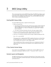
... message is displayed by manually pressing the compute module power button. 3. When the BIOS Setup Utility is entered, the Main screen is displayed during boot time. General Layout and Navigation The BIOS Setup page layout is used to the Intel® Modular Server System MFSYS25/MFSYS35 User Guide for the Intel® Compute Module MFS5520VI's built-in devices, boot...
... message is displayed by manually pressing the compute module power button. 3. When the BIOS Setup Utility is entered, the Main screen is displayed during boot time. General Layout and Navigation The BIOS Setup page layout is used to the Intel® Modular Server System MFSYS25/MFSYS35 User Guide for the Intel® Compute Module MFS5520VI's built-in devices, boot...

User Guide
Page 116
... 2 636 9797 (via Philippines) Japan Domestic.... 0120 868686 Outside country ... 81 298 47 0800 Latin America Argentina .. Once connected, dial 800 843 4481 102 Intel® Compute Module MFS5520VI User Guide Once connected, dial 800 843 4481 Mainland and Juan .. You need an IDD-equipped telephone) Indonesia ... 803 65 7249 Korea ......... 822 767 2595... Vietnam ..... 632 6368416 (IDD via Philippines) China ......... 800 820 1100 (toll-free 8 621 33104691 (not toll-free) Hong Kong 852 2 844 4456 India........... 0006517 2 68303634 (manual toll-free.
... 2 636 9797 (via Philippines) Japan Domestic.... 0120 868686 Outside country ... 81 298 47 0800 Latin America Argentina .. Once connected, dial 800 843 4481 102 Intel® Compute Module MFS5520VI User Guide Once connected, dial 800 843 4481 Mainland and Juan .. You need an IDD-equipped telephone) Indonesia ... 803 65 7249 Korea ......... 822 767 2595... Vietnam ..... 632 6368416 (IDD via Philippines) China ......... 800 820 1100 (toll-free 8 621 33104691 (not toll-free) Hong Kong 852 2 844 4456 India........... 0006517 2 68303634 (manual toll-free.

User Guide
Page 121
... the WARNING is ignored. Safety Warnings and Cautions To avoid personal injury or property damage, before installing or maintaining your server manuals to all warnings and precautions in this document and information provided with the product or on the product and / or ...approvals of a hazard that result in which the product is ignored. Indicates shock hazards that may result in your Intel® server product. Intel® Compute Module MFS5520VI User Guide 107 You must adhere to the guidelines in this guide. The following safety instructions and information. Indicates...
... the WARNING is ignored. Safety Warnings and Cautions To avoid personal injury or property damage, before installing or maintaining your server manuals to all warnings and precautions in this document and information provided with the product or on the product and / or ...approvals of a hazard that result in which the product is ignored. Indicates shock hazards that may result in your Intel® server product. Intel® Compute Module MFS5520VI User Guide 107 You must adhere to the guidelines in this guide. The following safety instructions and information. Indicates...
